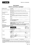
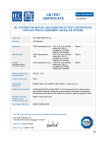
Download TEST REPORT MEDICAL ELECTRICAL EQUIPMENT
Transcript
Nemko ref. no.: 200043138 TEST REPORT MEDICAL ELECTRICAL EQUIPMENT Equipment / Product LCD type Computer Name and address of the applicant Advantech Co., Ltd. 4F, No. 108-3, Ming-Chuan Road. Shing-Tien City, Taipei TAIWAN, R.O.C. Name and address of the manufacturer Advantech Co., Ltd. 4F, No. 108-3, Ming-Chuan Road., Shing-Tien City, Taipei TAIWAN, R.O.C. Name and address of the factory Advantech Co., Ltd. Fl. 7, NO. 1, Lane 169, Kang-Ning Street Xi-Zhi Town, Taipei Hsien TAIWAN, R.O.C. Trade mark ADVANTECH Model/type PPC-xxyM (Explanation for xxy on page 3 in this report) Rating and principal characteristics 100-250Vac, 3A, 50/60Hz, Class I equipment Serial no Test sample(s) received, date 24. oct. - 2000 Tested in the period, dates Oct. -Nov. - 2000 Tested according to IEC 60601-1 (2 ed 1988) + Amend. 1 (1991) + Amend. 2 (1995) + Corrigendum (June 1995) MEDICAL ELECTRICAL EQUIPMENT - Part 1: General requirements for safety Result of testing The equipment complies with the above mentioned standards. The test results relate only to the sample(s) tested. Name and address of the testing laboratory P.O. BOX 73 BLINDERN, N - 0314 OSLO, NORWAY Telephone (+47) 22 96 03 30 Fax (+47) 22 96 05 50 Tested by Signature Johny Giang date Signature Frank Skarpsno date Verified by © Nemko AS Verdicts are placed in the column to the right.: P = Pass, F = Fail, N = Not applicable, = Considered/Information. Due to Nemko’s computerised handling of test reports the layout of this form is modified compared to the original TRF published by EMEDCA; 1992-12-01. The content fully covers the original TRF. This form is only for use by Nemko, or by others according to special agreement with Nemko. The completed test report is not valid for external use, unless issued by Nemko or attached to a Nemko certification document. The report shall not be reproduced without written permission from Nemko and may then only be copied in full. Issue Nemko 97-09-05 Page 1 of 73 Nemko ref. no.: 200043138 DESCRIPTION OF EQUIPMENT UNDER TEST: The PPC-150 panel PC is a multimedia Pentium MMX processor-based computer that is designed to serve as a human machine interface (HMI) and as a desktop computer. It is a PCbased system with 15” color TFT LCD display, on-board PCI Ethernet controller, multi-COM port interfaces and a 16-bit audio controller. With built-in CD-ROM drive, floppy drive and PCMCIA ezpansion sockets. NAME AND ADDRESS OF PRODUCTION-SITES (FACTORIES): See front page. INFORMATION ABOUT THE STANDARDS / DOCUMENTS CONSIDERED: EN 60601-1 (1990) + A1 (1993) + A2 (1995) +A13 (1996) + Corrigenda (July 1994). EMC standard : EN 60601-1-2 (1993) TESTED ACCORDING TO NATIONAL REQUIREMENTS FOR THE FOLLOWING COUNTRIES: LIST OF APPENDIXES / ENCLOSURES TO THE TEST REPORT: See page 4. Page 2 of 73 Nemko ref. no.: 200043138 SUMMARY OF TESTING Evaluation of Results If not explicitly stated otherwise in the standard, the test is passed if the measurement value is equal to or below the limit line, regardless of the uncertainty of the measurement. If the measurement value is above the limit line, the test is not passed - ref. IEC 60EE/CTL (sec) 056/94 (CLT = Committee of Testing Laboratories). The instrument accuracy is within limits agreed by this committee (ref. Nemko proc P227): Models PPC-xxyM where xx can be 12 or 15 for 12” LCD or 15” LCD where y can be 0-9 This computer uses adaptor (Skynet, Model SNP -8086-M which has CB) Clause Remarks Information/Comments Page 3 of 73 Nemko ref. no.: 200043138 LIST OF ATTACHMENTS PROVIDING FURTHER INFORMATION ON THE EQUIPMENT TESTED AND THE TEST METHODS The following attachments are added to this TRF or kept in file at the Testing Station mentioned at the cover page: Statements on calibrations and measurement uncertainties (where relevant) of the measurement and test equipment as identified throughout this TRF: Calibration All instruments used in the tests given in this report are calibrated and traceable to international standards. Further information about tractability will be given on request. Measurement uncertainties Measurements uncertainties are calculated for all instruments and instruments set-ups given in this report. Calculations are based on the principles given in the standard EA -4/02 (Dec. 1999). Further information about measurements uncertainties will be given on request Document title/identification: Kept in file at Nemko; P31000 ATT. No.: Not attached Lis t of worksheets which describe measurement procedures or test methods where practicable: Document title/identification: Kept in file at Nemko; P31000 ATT. No.: Not attached List of equipment or units tested and/or accompanying units and accessories (in case not all individual units can be mentioned on the front-page): Document title/identification: See summary of testing in this report. ATT. No.: Not attached Technical design documents of components having basic, supplementary of reinforced insulation (e.g. transformer specification mentioning the insulation class of the insulation materials applied - A to H): Document title/identification: Kept in file at Nemko ATT. No.: Not attached Description of safety systems (specifying for example safety circuits, redundant circuits, double circuits, hardware/software safety measures, temperature controls, etc.): Document title/identification: Kept in file at Nemko ATT. No.: Not attached PERSONNEL - INITIALS USED THROUGHOUT THIS TRF Initials: Full name: Signatures: This Part 1 TRF contains 73 pages, numbered from 1 to 73. This TRF contains photographs. Attachment no. 1 Attachment no. 2. EMC report no. 200045135 Page 4 of 73 Nemko ref. no.: 200043138 3 GENERAL REQUIREMENTS 3.1 EQUIPMENT when transported, stored, installed, operated in NORMAL USE and maintained according to the instructions of the manufacturer, causes no SAFETY HAZARD which could reasonably be fore- seen and which is not connected with its intended application in NORMAL CONDITION and in S.F.C. The equipment causes no hazards when used according the manufacturers instructions. P 3.4 An alternative means of construction is used to that detailed in this standard and it can be demonstrated that an equivalent degree of safety is obtained. No alternative construction. N 5 CLASSIFICATION 5.1 Type of protection against electric shock. Class I equipment. 5.2 Degree of protection against electric shock. No applied part. This is a Personal Computer. As the equipment is not intended to be connected to the patient and does not have any patient applied parts, it is not marked with the type B applied part symbol. 5.3 Classification of the equipment against ingress of liquids. Ordinary equipment. 5.5 Degree of safety of application in the presence of a FLAMMABLE ANAESTHETIC MIXTURE WITH AIR or WITH OXYGEN OR NITROUS OXIDE The equipment is not an AP or APG category equipment. 5.6 Mode of operation. Continuous operation. Page 5 of 73 Nemko ref. no.: 200043138 INSULATION DIAGRAM Refer to table on next page. Protection against electric shock Block diagram of system P Drawing A-a2 A-f Prim. Sec. A-e A-k B-a Comments Page 6 of 73 Nemko ref. no.: 200043138 TABLE TO INSULATION DIAGRAM ON PREVIOUS PAGE Distance (Test Refer to 20.1 + 20.2) Insulation type Basic/Supplement./ Double/Reinforced Insulation Maximum circuit voltage Required distances (mm) Clearance Creepage Dielectric strength test voltage Refer to 20.3 A-a2 Double/Reinforce. 250 V a.c. 5,0 mm 8,0 mm 4 000 V a.c. A-k Double/Reinforce. 250 V a.c. 5,0 mm 8,0 mm 4 000 V a.c. A-e Double/Reinforce. 250 V a.c. 5,0 mm 8,0 mm 4 000 V a.c. A-f Basic 250 V a.c. 1,6 mm 3,0 mm 1 500 V a.c. B-a Double/Reinforce. 250 V a.c. 5,0 mm 8,0 mm 4 000 V a.c. Comments Page 7 of 73 Nemko ref. no.: 200043138 6 IDENTIFICATION, MARKING AND DOCUMENTS 6.1 Marking on the outside 6.1 a Markings of Mains operated EQUIPMENT 6.1 b Markings of Internally Powered EQUIPMENT Not applicable. Not internally powered equipment N 6.1 c Markings of EQUIPMENT supplied from a specified power supply Not applicable. N 6.1 d Minimum requirements if limited space for marking Not applicable. N 6.1 e Name and/or trademark of the manufacturer or supplier See front page P 6.1 f Model or type reference See front page P 6.1 g Rated supply voltage(s) or voltage range(s) Number of phases Type of current 100-250 V ∼ Single phase a.c. P Rated frequency or rated frequency range(s) in Hz 50/60 Hz. 6.1 h Example of marking label: P 3A P Page 8 of 73 Nemko ref. no.: 200043138 6.1 j Rated power input (VA, W or A) 3A P 6.1 k Power output of auxiliary mains socket outlets No N 6.1 l Class II symbol Not applicable. Not Class II. N Symbol for degree of protection with respect to harmful ingress of water according to EN 60529 (IPX0 not required to be marked) Ordinary equipment. IP X0. N Symbol for protection against electric shock: Personal Computer. As the equipment is not intended to be connected to the patient and does not have any patient applied parts, it is not marked with the type B applied part symbol. N 6.1 m Mode of operation (if no marking, suitable for continuous operation) Continuous operation. P 6.1 n Types and rating of external accessible fuses No external fuses. N 6.1 p Rated output voltage and current or power, output frequency (where applicable) No auxiliary mains socket outlets. N 6.1 q Symbol for physiological effect(s): Not applicable. No need for marking. N 6.1 r Anaesthetic-proof symbol: Not of category AP or APG. N 6.1 s High voltage symbol: 6.1 t Special cooling requirements Fan used P 6.1 u) Limited mechanical stability 10° P 6.1 v Protective packing requirement(s). Marking(s) for unpacking safety hazard(s) 6.1 y Earth terminals: 6.1 z Removable protective means Durability of markings Symbol 6 of table DII, Dangerous voltage is used. N P Appliance inlet used P P Tested with a cloth of rack soaked with, in turn, water, methylated spirit and isopropyl alcohol. P The sample label withstood the test. 6.2 Marking on the inside 6.2 a Marking clearly legible 6.2 b P Nominal supply voltage of permanently installed equipment marked inside or outside of equipment Not permanently installed equipment N Maximum power loading of heating elements or lamp holders for heating lamps clearly and indelibly marked near or in the heater No heating elements used N Heating elements or lamp holders for heating lamps not intended to be changed by operator and which can be changed only with the use of a tool, have at least an identifying marking referring to information stated in the accompanying documents N Page 9 of 73 Nemko ref. no.: 6.2 c High voltage parts: 6.2 d Type of battery and mode of insertion (if applicable) marked (see Sub-clause 56.7 b) Symbol 6 of table DII, Dangerous voltage Back up battery. Type M4T28-BR12SH1, rating 5V, 50mAh Fuse type and rating or reference stated is used. P P P Batteries not intended be changed by operator and which can be changed only with use of tool have at least marking referring to information in accompanying documents 6.2 e 200043138 GBP, 12A, 250Vac P P 6.2 f Protective earth terminal marked 6.2 g Functional earth terminal marked Not applicable. N 6.2 h Terminals for supply neutral conductor in permanently installed equipment marked (N) Not applicable. N 6.2 j Markings required in Sub-clause 6.2 f, h, k and l P 6.2 k The supply connections are clearly marked adjacent to the terminals or in accompanying documents (for small equipment) P 6.2 l Statement for suitable wiring materials (at temperatures over 75°C) locates at or near the point of the supply connections and is clearly discernible after connection Not applicable. N 6.2 n Capacitors and/or circuit parts are marked as required in Sub-clause 15 c Not applicable. N 6.3 Marking of controls and instruments 6.3 a Mains switch clearly identified. ”On” and “off” positions marked or otherwise indicated 6.3 b Adequate indications of different positions of controls and other switches 6.3 c Adequate indication of the direction of setting devices if change of setting of a control could cause a safety hazard N 6.3 f Functions of operator controls and indicators identified N 6.3 g Numeric indications of parameters are in SI units according to ISO 1000. Units outside the International System as specified N 6.4 Symbols 6.4 a Marking symbols compliance with appendix D, where applicable P Not applicable. N P Page 10 of 73 Nemko ref. no.: 6.4 b 200043138 Symbols for controls and performance conform to IEC 60 878, where applicable Not applicable. N Durability of marking symbols Tested in Clause 6.1. P 6.5 Colours of insulation of conductors 6.5 a Protective earth conductor has green/yellow insulation P 6.5 b All insulations of internal protective earth conductors are green/yellow, at least at the terminations of the conductors P 6.5 c Only protective earth-, functional earth-, potential equalisation and inside earthing conductors (cf. 6.5 b) are green/yellow 6.5 d Colour of neutral conductor: light blue according to IEC 60 227 or 245 P 6.5 e Colours of phase conductors in power supply cord according to IEC 60 227 or 245 P 6.5 f Additional protective earthing in multiconductor cords are marked green/yellow at the ends of the additional conductors P 6.6 Identification of medical gas cylinders and connections 6.6 a Identification of content in accordance with ISO/R32 6.6 b Identification of connection point that errors are avoided when a replacement is made Not used No medical gas used N N N Page 11 of 73 Nemko ref. no.: 6.7 Indicator lights and push-buttons 6.7 a Colour red only used for warning of danger or/and need for urgent action. Dot-matrix/alphanumeric displays not considered to be indicator lights 6.7 b Colours of unilluminated push-buttons. Colour red only used in case of emergency Location Meaning of indicator lights 200043138 No colour red used N N Illuminated push-button (see IEC 60 73) Colour — — — — — — — — 6.8 Accompanying documents 6.8.1 Equipment is accompanied at least by - instructions for use User Manual P - technical description User Manual P - an address to which the user can refer User Manual P All applicable classifications specified in Clause 5 are included in instructions for use and technical description User Manual P P markings in Sub-clause 6.1 included in accompanying documents if not permanently affixed to equipment Warning statements and explanations of warning symbols are provided in accompanying documents Not used N Language of accompanying documents English. Will be in the language required for the market where the equipment is intended to be sold. P Page 12 of 73 Nemko ref. no.: 6.8.2 Instructions for use 6.8.2 a General information Necessary information to operate the equipment P Explanation of the function of controls, displays and signals P Sequence of operation P Connection and disconnection of detachable parts and accessories Detachable power supply cord P Replacement of material which is consumed during operation Not applicable. N Indications of recognised accessories, detachable parts and materials, if the use of other parts or materials can degrade minimum safety Not applicable. N Cleaning, preventive inspection and maintenance to be performed including the frequency of such maintenance User Manual P Information about safe performance of routine maintenance P Information about preventive inspection and maintenance to be performed by other persons P Meanings of figures, symbols, warning statements and abbreviations on equipment explained in the instructions for use P Instruction for use states the function and intended application of equipment P Instructions for use provide user with information regarding potential electromagnetic or interference and advice how to avoid such interference 6.8.2 c Not applicable. N Not applicable. N Properly described. P Signal output and signal input parts Signal output or signal input parts intended only for connection to specified equipment stated in instruction for use 6.8.2 d 200043138 Cleaning, disinfection and sterilisation of parts in contact with the patient Details about cleaning or disinfection or sterilisation methods that may be used for equipment parts which come into contact with the patient during normal use given in instruction for use Page 13 of 73 Nemko ref. no.: 6.8.2 e 6.8.2 f 200043138 Mains operated equipment with additional power source A warning statement referring to the necessity for periodical checking or replacement of an additional power source Not applicable. No used of additional power source N If Class I equipment a statement saying that where the integrity of the external protective conductor in the installation or its arrangement is in doubt, equipment shall be operated from its internal electrical power source Not applicable. N Removal of primary batteries (i.e. not rechargeable batteries): No primary batteries used N Instruction for use contains a warning to remove batteries if equipment is not likely to be used for some time ,unless no risk of safety hazard 6.8.2 g Rechargeable batteries: Not rechargeable batteries N Instructions to ensure safe use and adequate maintenance 6.8.2 h Equipment with a specified power supply or battery charger: Instructions for use identify power supplies or battery chargers necessary to ensure compliance with the requirements of IEC 601-1 Not applicable. N 6.8.2 j Instructions for use identify risks associated with disposal of waste, residues etc. and of equipment/accessories at end of their lives. Further it provides advice on minimising these risks Not applicable. N 6.8.3 Technical description 6.8.3 a General Technical description provides all data essential for safe operation including data in Sub-clause 6.1 and all characteristics of the equipment The Technical and Service Manual is well written and contains all necessary information required. P A statement whether particular measures or particular conditions are to be observed for installing equipment and bringing equipment into use Not applicable. N Required type and rating of fuses utilised in the mains supply circuit external to permanently installed equipment Not applicable. Notpermanently installed equipment N Instructions for replacement of interchangeable and/or detachable parts which are subject to deterioration during normal use Not applicable. N 6.8.3 b Replacement of fuses and other parts : Page 14 of 73 Nemko ref. no.: 6.8.3 c Circuit diagrams, component part lists, etc.: The technical description contains a statement that the supplier will make available on request circuit diagrams, component part lists, descriptions, calibration instructions, etc. in order to assist user in case of necessary reparations 6.8.3 d 200043138 Not applicable. N Environmental conditions for transport and storage: The technical description contains a specification of the permissible environmental conditions for transport and storage P The above said specification also repeated on the outside of the packaging P 7 POWER INPUT 7.1 Steady state current or power input does not exceed the marked rating by more than specified Input power: 100-250Vac, 3A, 50/60Hz Equipment: N3635 Initials Tester / Date: JohnyG / 10-2000 Power input Function Input current Normal operation (A) Standby (A) P Deviation: (measured-rated)*100/rated = % UNlower = 90 V UN = 170 V UN upper = 275V 1,4/1,4 0,98/0,98 0,6/0,6 — — — Input power Normal operation (W) 69/69 68/67 68/68 Input power Normal operation (VA) — — — Power factor cos ϕ 0,54/0,54 0,48/0,47 0,40/0,41 Comments Power input rated is measured at both 50 and 60Hz. The 50Hz values are showed before “/” and the 60Hz is back. (Remark: #PPC-15yM-zT) 10 ENVIRONMENTAL CONDITIONS 10.1 Equipment capable, while packed for transport and storage, of being exposed to environmental conditions as stated by manufacturer (see 6.8.3 d) Considered OK. P 10.2 Operation of equipment according to specified environment and power supply Considered OK. P Page 15 of 73 Nemko ref. no.: 13 200043138 GENERAL Equipment so designed that risk of electric shock obviated as far as practicable (requirements as given in section three) Considered OK. P 14 REQUIREMENTS RELATED TO CLASSIFICATION 14.1 Class I equipment 14.1 a Parts with Double Insulation Transformer P Parts with Reinforced Insulation Transformer P Parts with SELV-Voltage N Parts with Protective Impedance N No external d.c. power source used N Class II equipment is of one of the following types: Not applicable. Class I equipment N If equipment is fitted with a device for changing over from class I to class II protection, the following requirements are fulfilled: Not applicable. N 14.1 b If the mains part of equipment specified for an external d.c. power source is isolated from accessible conductive parts by basic insulation only, a separate protective earth conductor is provided 14.2 Class II equipment 14.2 a 14.2 b The change-over device indicates the selected class clearly N A tool for change-over is necessary N The equipment complies with all requirements for the selected class at any given time N Class II position: The device interrupts the connection of protective earth conductor to equipment or changes it into functional earth conductor (compliance with 18.2) N 14.2 c Class II equipment provided with functional earth connections (cf. Subclause 18 k and l) N 14.4 Class I and II equipment 14.4 a Equipment is provided with an additional protection according to the requirements of Class I or Class II equipment P Page 16 of 73 Nemko ref. no.: 14.4 b No safety hazard develop, when a connection with the wrong polarity is made in equipment specified for power supply from an external d.c. power source (e.g. for use in ambulances) 14.5 Internally powered equipment 14.5 b Equipment also having means of connection to supply mains complies also with requirements for Class I or II while so connected 14.6 Types B, BF and CF applied parts 14.6 c Applied parts suitable for direct cardiac application are of type CF 200043138 Not applicable. N Not applicable. N Not applicable. N Page 17 of 73 Nemko ref. no.: 200043138 15 LIMITATION OF VOLTAGE AND/OR ENERGY 15 b Equipment with mains plug so designed that the voltage 1 sec. after disconnection does not exceed 60 V P Interference suppression capacitors P 3300pF Capacitance between each line and protective earth. Measured value P N2843 Equipment: JohnyG / 10-2000 Initials Tester / Date: Maximum residual voltage in the mains plug 1 second after disconnection (measured in the least favourable position of the on-off switch, if any): Remark: pins 1 and 2 are Line and Neutral supply pins. Note! PE is equal to enclosure. Measurement no. 1 2 2 4 5 6 7 8 9 10 Voltage between pins 1 and 2 (Limit 60 V) 14 14 14 14 14 14 14 14 14 14 Voltage between pin 1 and PE (Limit 60 V) 14 14 14 14 14 14 14 14 14 14 Voltage between pin 2 and PE (Limit 60 V) 14 14 14 14 14 14 14 14 14 14 15 c Accessible live parts of capacitors or related circuits having a residual voltage above 60 V does not have a residual energy above 2 mJ (see 15 c below) Not applicable. N N A non-automatic discharging device is included and marked Equipment: Initials Tester / Date: Capacitor and its location Working voltage (V) / Capacitance value (mF) Residual voltage (V) Residual energy (mJ) Page 18 of 73 Nemko ref. no.: 200043138 16 ENCLOSURES AND PROTECTIVE COVERS 16 a Protection against contact with live parts. P - and with parts which can become live in single fault conditions P Instruction for use instructs operator not to touch such parts and the patient simultaneously Not applicable. No such parts Equipment: Standard test finger : Initials Tester / Date: Location of opening N Our ref. N 2489 JohnyG / 10-2000 Test result finger Back of equipment OK 16 b Check of openings in top covers with the vertical suspended test rod No openings in the top covers N 16 c Conductive parts of actuating mechanism of electrical controls after the removal of handles, knobs, levers etc. have either resistance to the protective earth terminal max. 0.2 ohms or the separation from live parts complies with 17 g Not applicable. N 16 d Protection of contact with internal parts of the equipment with a circuit voltage exceeding 25 V a.c. or 60 V d.c. which cannot be disconnected from the supply by external mains switch or plug device Not applicable. N Equipment: Initials Tester / Date: Location of part Covering Warning notice Remarks 16 e Protective enclosures are removable only with the aid of tool or an automatic device makes these parts not live, when the enclosure is opened or removed Only with the aid of tool P 16 f Live parts are inaccessible to the test rod through openings for adjustment of pre-set controls Not applicable. N Page 19 of 73 Nemko ref. no.: 200043138 17 SEPARATION 17 a Separation method of the applied part from live parts so that allowable leakage currents are not exceeded 17 a 1 Basic insulation - applied part earthed N 17 a 2 By protectively earthed conductive part (e.g. screen) N 17 a 3 By separate earthed intermediate circuit N 17 a 4 By double or reinforced insulation N 17 a 5 By protective impedances limiting current to applied part 17 a 6 Other method, e.g. specified in particular standard No applied part . N N Equipment: Initials Tester / Date: Additional leakage current test in single fault conditions Fault condition (description) Earth leakage current Enclosure leakage current 17 c There is no conductive connection between applied parts and accessible conductive parts, which are not protectively earthed 17 d Supplementary insulation between hand-held flexible shafts and motor shafts (Class I equipment) Patient leakage current Patient auxiliary current P Not used N Adequate isolation of accessible metal parts from motor shaft N Rated motor voltage N Test voltage N Air clearances/creepage distances (mm)/(mm) N 17 g Separation method of accessible parts other than applied parts from live parts so that allowable leakage currents are not exceeded 17 g 1 Basic insulation - accessible part earthed P 17 g 2 By protectively earthed conductive part (e.g. screen) P 17 g 3 By separate earthed intermediate circuit Not applicable. N 17 g 4 By double or reinforced insulation Transformer N Page 20 of 73 Nemko ref. no.: 17 g 5 17 h 200043138 By protective impedances limiting current to accessible part N Leakage currents measurements, when required N Adequate arrangements used to isolate defibrillation-proof applied parts from other parts N Impulse voltage tests N Peak voltage between Y1 and Y2 does not exceed 1 V N After recovery time equipment continues to perform its intended function N 18 PROTECTIVE EARTHING, FUNCTIONAL EARTHING AND POTENTIAL EQUALIZATION 18 a Sufficiently low impedance to the protective earth terminal(18 f and 18 g) P 18 b Suitable connection between protective earth terminal and protective conductor in the installation (18 f) P 18 e Means for connection of potentially equalisation conductor complies with specified requirements Not used N This connection complies with following requirements: N - readily accessible N - no possibility to accidental disconnection in normal use N - conductor is detachable without the use of a tool N - power supply cord does not include potential equalisation conductor N - connection is marked with symbol N Page 21 of 73 Nemko ref. no.: 18 f Impedance of protective earthing system: Impedance between any accessible metal part and: 1) protective earth terminal (PE) (requirement: R max. 0.1 Ohm), 2) protective earth contact in appliance inlet (requirement: R max. 0.1 Ohm), 3) protective earth contact in the mains plug Test equipment: See attached list. (requirement: R max. 0,2 Ohm), are tabled below: U = 0,57V Equipment: N1514, N2332, N1585 Initials Tester / Date: 200043138 P I = 30A T = 2min. JohnyG / 11-2000 Accessible part and its location R (Ohm) measured against (numbers see above) 1 PE Inlet- Ground 2 inlet 3 plug 0,019 18 g If the impedance of protective earth connections other than in 18 f exceeds 0.1 Ohm, the allowable value of the enclosure leakage current is not exceeded in single fault condition 18 k Functional earth terminals are not used to provide protective earthing 18 l For Class II equipment with isolated internal screens and with a power supply cord: No N P Class I equipment N - the third conductor is used only as functional earth of these screens and is coloured green/yellow N - insulation of such screens and all internal wiring connected to them is double insulation or reinforced insulation (see also 20.3) N - marking of functional earth terminal is distinguished from protective earth terminal and is explained in accompanying documents N Test of insulation (see Clause 20) N Page 22 of 73 Nemko ref. no.: 200043138 19 CONTINUOUS LEAKAGE CURRENTS AND PATIENTS AUXILIARY CURRENTS 19.1 General requirements (tests see 19.4) 19.1 g Equipment with multiple patient connections: Patient leakage current and patient auxiliary current do not exceed allowable values while one or more patient connections are disconnected from the patient or disconnected from the patient and earthed 19.2 Single fault conditions (tests see 19.4) 19.3 Allowable values (see 19.4) 19.4 Tests before humidity preconditioning treatment See comment below. Equipment: N2239, N2718, N2266,N3171 Initials Tester / Date: JohnyG / 11-2000 Type of leakage current Not applicable. N In normal condition In single fault condition Allowed value (µA) Allowed value (µA) Measured max. value (µA) Measured max. value (µA) Earth leakage current 500 184 1000 381 Enclosure leakage current 100 <5 500 <5 Patient leakage current (p.l.c.), a.c. : B, BF: CF: 100 10 — B, BF: CF: 500 50 — Patient leakage current (p.l.c.), d.c. : B, BF: CF: 10 10 — B, BF: CF: 50 50 — P.l.c. (110 % of the mains voltage on the signal input part or signal output part) — — B: BF, CF: 5000 — 113 P.l.c. (110 % of mains voltage on the applied part) — — B: BF: CF: — 5000 50 — Patient auxiliary current, a.c. : B, BF: CF: 100 10 — B, BF: CF: 500 50 — Patient auxiliary current, d.c. : B, BF: CF: 10 10 — B, BF: CF: 50 50 — Comments The values listed are the maximum values. Page 23 of 73 Nemko ref. no.: 19.4 Tests after humidity preconditioning treatment See comments below. Equipment: N2239, N2718, N2266,N3171 JohnyG / 11-2000 Initials Tester / Date: Type of leakage current 200043138 In normal condition In single fault condition Allowed value (µA) Allowed value (µA) Measured max. value (µA) Measured max. value (µA) Earth leakage current 500 185 1000 382 Enclosure leakage current 100 <5 500 <5 Patient leakage current (p.l.c.), a.c. : B, BF: CF: 100 10 — B, BF: CF: 500 50 — Patient leakage current (p.l.c.), d.c. : B, BF: CF: 10 10 — B, BF: CF: 50 50 — P.l.c. (110 % of the mains voltage on the signal input part or signal output part) — — B: BF, CF: 5000 — 113 P.l.c. (110 % of ma ins voltage on the applied part) — — B: BF: CF: — 5000 50 — Patient auxiliary current, a.c. : B, BF: CF: 100 10 — B, BF: CF: 500 50 — Patient auxiliary current, d.c. : B, BF: CF: 10 10 — B, BF: CF: 50 50 — Comments The values listed are the maximum values. Page 24 of 73 Nemko ref. no.: 20 200043138 DIELECTRIC STRENGTH (at operating temperature) P Overall compliance with Clause 20 Equipment Equipment: High voltage supply : N1979 Initials Tester / Date: JohnyG / 11-2000 Insulation under test Insulation resistance *) Reference voltage Test voltage Remarks, observations 250 V AC 1 500 V AC OK A-e 250 V AC 4 000 V AC OK A-f 250 V AC 1 500 V AC OK A-k 250 V AC 4 000 V AC OK Equipment B-a 250 V AC 4 000 V AC OK types with B-b applied part B-c All A-a1 equipment A-a2 types A-b A-c A-g A-j B-d B-e *) IEC 601-1 does not require to measure this Page 25 of 73 Nemko ref. no.: 20 200043138 DIELECTRIC STRENGTH (after humidity preconditioning treatment) P Overall compliance with Clause 20 Humidity room : N3205 High voltage supply : N601 Equipment: JohnyG / 11-2000 Initials Tester / Date: Equipment Insulation under test Insulation resistance *) Reference voltage Test voltage Remarks, observations 250 V AC 1 500 V AC OK A-e 250 V AC 4 000 V AC OK A-f 250 V AC 1 500 V AC OK A-k 250 V AC 4 000 V AC OK Equipment B-a 250 V AC 4 000 V AC OK types with B-b applied part B-c All A-a1 equipment A-a2 types A-b A-c A-g A-j B-d B-e *) IEC 601-1 does not require to measure this 21 MECHANICAL STRENGTH 21 a Rigidity of enclosure (45 N test force) Tested with 45 N. No damage to enclosure parts. P 21 b Strength of enclosure part and any component thereon (Impact hammer test, 0.5 J). No damage resulting in a safety hazard. P 21 c On portable equipment carrying handles or grips withstand the requirements of the loading test. (Test force four times the weight of equipment) No handles or grips used N Page 26 of 73 Nemko ref. no.: 21.3 No damage to parts of patient support and/or immobilisation system after the loading test (1350 N and 2700 N tests) No patien support parts used 200043138 N N The test force for foot rests and chairs shall be twice the specified maximum load or, if not specified, the test force shall be 2,7 kN. The test force shall be distributed over an area of 0,1 m2 surface for 1 minute. Not hand-held equipment N 21.5 Hand-held equipment or equipment parts are safe after drop test (dropping height 1 m) 21.6 a Portable and mobile equipment is able to withstand rough handling. 21.6 b Propel test of mobile equipment (performed 20 times). Equipment complies with requirements of this standard. 22 MOVING PARTS 22.2 a Moving parts of transportable equipment are provided with guards which form an integral part of the equipment 22.2 b Moving parts of stationary equipment are provided with similar guards as above unless it is evident that equivalent protection is separately provided during installation N 22.3 Cords (ropes), chains and bands are confined so they cannot run off or jump out of their guiding devices N Other means used to prevent a safety hazard N Mechanical safeguard means are removable only with a tool N 22.4 Dangerous movements of equipment parts, which may cause physical injury to the patient, are possible only by the continuous activation of the control N 22.6 Parts of equipment subject to mechanical wear are accessible for inspection N P Not applicable. N No moving parts used N Page 27 of 73 Nemko ref. no.: 22.7 23 200043138 To remove an unexpected safety hazard caused by an electrically produced mechanical movement, there are means for emergency switching of a relevant part N The means for emergency switching are readily identifiable and accessible and do not introduce a further safety hazard N Current breaking capability N Means for stopping of movements operate as a result of one single action N SURFACES, CORNERS AND EDGES There are no rough surfaces, sharp corners, flange or frame edges and burrs which may cause injury or damage The edges are well rounded. P 24 STABILITY IN NORMAL USE 24.1 Equipment does not overbalance, when tilted through an angle of 10° Tested. P 24.3 If equipment overbalances when tilted 10°, it does not overbalance when tilted: See above N - 5° in any position of normal use, excluding transport N - 10° in the condition specified for transport N The equipment carries a warning notice for transport N Equipment or its parts with a mass of more than 20 kg: N - is provided with handling devices (grips etc.) N - is provided with handling instructions for lifting and assembling N 4.6 b Portable equipment with a mass of more than 20 kg carrying handle(s) suitably placed that equipment may be carried by 2 or more persons N 25 EXPELLED PARTS 25.1 Protective means are provided where expelled parts of the equipment could constitute a safety hazard 24.6 a Not applicable. N Page 28 of 73 Nemko ref. no.: 25.2 Display vacuum tubes with a face dimension of 16 cm or larger are intrinsically safe with respect to effects of implosion of tubes and to mechanical impact, or the enclosure of the equipment is provided with adequate protection against implosion Not applicable. N N Certificate of the test provided 26 200043138 VIBRATION AND NOISE No general requirement. 27 PNEUMATIC AND HYDRAULIC POWER No general requirement. 28 SUSPENDED MASSES 28.3 Suspension systems with safety devices: No suspended masses N Suspension systems include a safety device with adequate safety factors to protect user or patient from hazards N If after activation of a safety device the equipment can still be used, the activation of the device, e.g. a secondary rope, becomes obvious to the operator N Suspension systems of metal without safety devices: N The construction of the suspension complies with: N 28.4 1 The TOTAL LOAD does not exceed the SAFE WORKING LOAD N 28.4 2 Where it is unlikely that supporting characteristics will be impaired by wear, corrosion, material fatigue or ageing, the SAFETY FACTOR of all supporting parts is not less than 4 N 28.4 3 Where impairment by wear, corrosion, material fatigue is expected, the SAFETY FACTOR is not less than 8 N 28.4 4 Where metal having a specific elongation at break of less than 5% is used in supporting components, the SAFETY FACTOR is not less than 1.5 times those given in 2) and 3) above N 28.4 Page 29 of 73 Nemko ref. no.: 200043138 N 28.4 5 Sheaves, sprockets, band wheels and guides are so designed that the SAFETY FACTORS of this Subclause shall be maintained for a specified minimum life till replacement of the ropes, chains and bands 28.5 Dynamic loads: 29 X-RADIATION 29.1 Diagnostic X-ray equipment, see IEC 601-1-3. Radiotherapy equipment, see relevant Particular standard 29.2 For equipment not intended to produce X-radiation for diagnostic and therapeutic purposes, ionising radiation emitted by vacuum tubes excited by voltages exceeding 5 kV does not produce an exposure exceeding 130 nC/kg (0.5 mR) 30 ALPHA, BETA, GAMMA, NEUTRON RADIATION AND OTHER PARTICLE RADIATION No general requirement. No X-radiation N N No general requirement. 31 MICROWAVE RADIATION No general requirement. 32 LIGHT RADIATION (INCLUDING LASERS) No general requirement. 33 INFRA-RED RADIATION No general requirement. 34 ULTRAVIOLET RADIATION No general requirement. 35 ACOUSTICAL ENERGY (INCLUDING ULTRA-SONICS) No general requirement. Page 30 of 73 Nemko ref. no.: 36 ELECTROMAGNETIC COMPATIBILITY IEC 60601-1-2 ( 1993 ) 37 - 41 200043138 Compliance documented by the manufacturer. P REQUIREMENTS FOR CATEGORY AP AND APG EQUIPMENT See additional test report form. Not applicable. N Page 31 of 73 Nemko ref. no.: 42 EXCESSIVE TEMPERATURES Ambient temperature during measurements: See tables below. Humidity: 40%rh Atmospheric pressure: 995hPa Equipment: Humidity : N2531 Pressure : N2842 JohnyG / 11-2000 Initials Tester / Date: 42.1 - 42.2 200043138 P Determination of the temperature with thermocouples: N3008, N3635, N2859, N3132 Equipment: JohnyG / 11-2000 Initials Tester / Date: Quantity Rated Used in tests Supply voltage, V 100-250V AC 90, 275 V AC Supply power, VA — — Output power, VA — — Measuring point Measured temp. ∆t (°K) A: IP 90Vac, 60Hz B: IP 275Vac, 60Hz Calculated temp. T (°C) Remarks Measured temp. ∆t (°K) A Calculated temp. T (°C) Allowed max. temp. T (°C) Remarks B 1. Ambient, T = 25° C — — — — — 2. T1 coil 40 80 43 68 Cl.B 130°C Table Xa 3. T1 core 36 76 39 64 “” Table Xa 4. L1 coil 35 60 30 55 Table Xb 5. BT1 body 26 51 26 51 Table Xb 6. V1 body 30 55 31 56 Table Xb 7. L6 coil 29 54 29 54 Table Xb 8. T1 coil for inverter 65 105 65 105 Cl.B 130°C Table Xa 9. T1 core for inverter 70 110 70 110 ”” Table Xa 10. F1 coil for inverter 58 83 58 83 11. Surface of PC 13 53 13 53 Table Xb 75 Table Xa 12. SMP for building-in: Skynet SNP-8086-M. See Nemko ref. 200039133 Comments According to IEC 601-1 clause 42.1, table Xa and Xb, 400 C or 250 C is added to the temperature rise for determination of the final temperature T. Model PPC-150M-zT Page 32 of 73 Nemko ref. no.: Measuring point Measured temp. ∆t (°K) A: IP 90Vac, 60Hz B: IP 275Vac, 60Hz Calculated temp. T (°C) Measured temp. ∆t (°K) A Calculated temp. T (°C) Allowed max. temp. T (°C) — 200043138 Remarks B 1. Ambient, T = 25° C — — — — 2. L1 coil 60 85 50 75 Table Xb 3. BD1 body 69 94 57 83 Table Xb 4. C8 body 46 71 42 67 Table Xb 5. T1 coil 70 110 76 116 Cl.B Table Xa 6. T1 core 67 107 73 113 «« Table Xa 7. L4 coil 76 101 79 104 Table Xb 8. L3 coil 61 86 63 88 Table Xb 9. HS body of Q1 41 66 42 67 Table Xb 10. V36 body 29 54 29 54 Table Xb 11.cpu body 37 62 36 61 Table Xb 12.H.DD body 25 50 25 50 Table Xb 13. F.DD body 19 44 19 44 Table Xb 14. CD rom body 27 52 27 52 Table Xb 15. V1 body 29 54 29 54 Table Xb 16. L48 body 26 51 26 51 Table Xb 17. T1 coil for inverter 62 102 62 102 Cl.B Table Xa 18. T1 core for inverter 48 88 48 88 “” Table Xa 19. L1 coil for inverter 56 81 56 81 13 53 13 53 20. Surface of PC Table Xb 75 Table Xa 12. SMP for building-in: Skynet SNP-8086-M. See Nemko ref. 200039133 Comments According to IEC 601-1 clause 42.1, table Xa and Xb, 400 C or 250 C is added to the temperature rise for determination of the final temperature T. Model PPC-120M-zT Page 33 of 73 Nemko ref. no.: Measuring point Measured temp. ∆t (°K) A: IP 90Vac, 60Hz B: IP 275Vac, 60Hz Calculated temp. T (°C) Measured temp. ∆t (°K) A Calculated temp. T (°C) Allowed max. temp. T (°C) — 200043138 Remarks B 1. Ambient, T = 25° C — — — — 2. L1 coil 52 77 43 68 Table Xb 3. BD1 body 65 90 50 75 Table Xb 4. C8 body 40 65 34 59 Table Xb 5. T1 coil 70 110 71 111 Cl.B Table Xa 6. T1 core 62 102 66 106 Cl.B Table Xa 7. L4 coil 70 95 71 96 Table Xb 8. L3 coil 56 81 56 81 Table Xb 9. HS body of Q1 37 62 37 62 Table Xb 10. BT1 body 19 44 18 43 Table Xb 11.V2 body 22 47 20 45 Table Xb 12. upc body 24 49 22 47 Table Xb 13. H.DD body 17 42 14 39 Table Xb 14. F.DD body 13 38 11 36 Table Xb 15. CD rom body 17 42 15 40 Table Xb 16. V3 body 25 50 24 49 Table Xb 17. T2 coil for inverter 57 97 57 97 Cl.B Table Xa 18. T2 core for inverter 54 94 55 95 Cl.B Table Xa 19. F3 coil for inverter 50 75 49 74 10 50 8 48 20. Surface of PC Table Xb 75 Table Xa 12. SMP for building-in: Skynet SNP-8086-M. See Nemko ref. 200039133 Comments According to IEC 601-1 clause 42.1, table Xa and Xb, 400 C or 250 C is added to the temperature rise for determination of the final temperature T. Model PPC-153M-zT Page 34 of 73 Nemko ref. no.: 42.1 - 42.2 Determination of the temperature with thermocouples: Block vent test P Measured temp. ∆t (°K) Calculated temp. T (°C) Allowed max. temp. T (°C) Ambient, T = 25° C — — — 1. L1 coil 60 85 Table Xb 2. BD1 body 67 92 Table Xb 3. C8 body 54 79 Table Xb 4. T1 coil 86 126 Cl.B Table Xa 5. T1 core 82 122 “” Table Xa 6. L4 coil 87 112 Table Xb 7. L3 coil 72 97 Table Xb 8. H.S body & Q1 53 87 Table Xb 9. V36 body 46 71 Table Xb 10.cpu body 55 80 Table Xb 11. H.DD body 34 59 Table Xb 12.F.DD body 24 49 Table Xb 13.CD rom body 38 63 Table Xb 14.V1 body 43 68 Table Xb 15.L48 body 44 69 Table Xb 16.T1 coil for inverter 68 108 Cl.B Table Xa 17.T1 core for inverter 55 95 “” Table Xa 18.L1 coil for inverter 53 78 19. Surface of enclosure 21 61 Measuring point 200043138 Remarks Power input 250Vac, 60Hz Comments Table Xb 75 Table Xa According to IEC 601-1 clause 42.1, table Xa and Xb, 400 C or 250 C is added to the temperature rise for determination of the final temperature T. Model PPC-120M Page 35 of 73 Nemko ref. no.: Measured temp. ∆t (°K) Calculated temp. T (°C) Allowed max. temp. T (°C) Ambient, T = 25° C — — — 1. L1 coil 60 85 Table Xb 2. BD1 body 67 92 Table Xb 3. C8 body 51 76 Table Xb 4. T1 coil 90 130 Cl.B Table Xa 5. T1 core 83 123 “” Table Xa 6. L4 coil 88 113 Table Xb 7. L3 coil 74 99 Table Xb 8. H.S body & Q1 55 80 Table Xb 9. BT1 body 39 64 Table Xb 10. V2 body 40 65 Table Xb 11. CPU body 43 68 Table Xb 12. HDD body 31 56 Table Xb 13. FDD body 23 48 Table Xb 14. CD rom body 29 54 Table Xb 15. U3 body 40 65 Table Xb 16.T2 coil for inverter 63 103 Cl.B Table Xa 17. T2 core for inverter 60 100 “” Table Xa 18. F3 coil for inverter 58 83 19. Surface of enclosure 25 65 Measuring point 200043138 Remarks Block vent test Power input 250Vac, 60Hz Comments Table Xb 75 Table Xb According to IEC 601-1 clause 42.1, table Xa and Xb, 400 C or 250 C is added to the temperature rise for determination of the final temperature T. Model PPC-153M Page 36 of 73 Nemko ref. no.: Measured temp. ∆t (°K) Calculated temp. T (°C) Allowed max. temp. T (°C) Ambient, T = 25° C — — — 1. T1 coil 65 105 Cl.B 2. T1 core 62 102 3. L1 coil 51 76 Table Xb 4. BT1 body 51 76 Table Xb 5. U1 body 58 83 Table Xb 6. L6 coil 56 81 Table Xb 7. T1 coil for inverter 70 110 Cl.B Table Xa 8. T1 core for inverter 77 117 Cl.B Table Xa 9. F1 coil for inverter 68 93 10. Surface of PC 34 73 Measuring point 200043138 Remarks Block vent test Power input 250Vac, 60Hz Comments Cl.B Table Xa Table Xa Table Xb 75 Table Xa According to IEC 601-1 clause 42.1, table Xa and Xb, 400 C or 250 C is added to the temperature rise for determination of the final temperature T. Model PPC-150M Page 37 of 73 Nemko ref. no.: 42.1 - 42.2 Determination of the temperature with thermocouples: Installed fan test P Measured temp. ∆t (°K) Calculated temp. T (°C) Allowed max. temp. T (°C) Ambient, T = 24° C — — — 1. L1 coil 50 75 Table Xb 2. BD1 body 57 82 Table Xb 3. C8 body 45 70 Table Xb 4. T1 coil 78 118 Cl.B Table Xa 5. T1 core 74 114 “” Table Xa 6. L4 coil 81 106 Table Xb 7. L3 coil 66 91 Table Xb 8. H.S body & Q1 44 69 Table Xb 9. V36 body 40 65 Table Xb 10.cpu body 73 98 Table Xb 11. H.DD body 32 57 Table Xb 12.F.DD body 18 43 Table Xb 13.CD rom body 28 53 Table Xb 14.V1 body 42 67 Table Xb 15.L48 body 54 79 Table Xb 16.T1 coil for inverter 61 101 Cl.B Table Xa 17.T1 core for inverter 47 87 “” Table Xa 18.L1 coil for inverter 57 82 19. Surface of enclosure 34 74 Measuring point 200043138 Remarks Power input 250Vac, 60Hz Comments Table Xb 75 Table Xa According to IEC 601-1 clause 42.1, table Xa and Xb, 400 C or 250 C is added to the temperature rise for determination of the final temperature T. Model PPC-120M Page 38 of 73 Nemko ref. no.: Measured temp. ∆t (°K) Calculated temp. T (°C) Allowed max. temp. T (°C) Ambient, T = 25° C — — — 1. L1 coil 49 74 Table Xb 2. BD1 body 56 81 Table Xb 3. C8 body 42 67 Table Xb 4. T1 coil 78 118 Cl.B Table Xa 5. T1 core 73 113 “” Table Xa 6. L4 coil 81 106 Table Xb 7. L3 coil 66 91 Table Xb 8. H.S body & Q1 47 72 Table Xb 9. BT1 body 39 64 Table Xb 10. U2 body 68 93 Table Xb 11. CPU body 72 97 Table Xb 12. HDD body 23 48 Table Xb 13. FDD body 13 38 Table Xb 14. CD rom body 20 45 Table Xb 15. U3 body 38 63 Table Xb 16.T2 coil for inverter 55 95 Cl.B Table Xa 17. T2 core for inverter 52 92 “” Table Xa 18. F3 coil for inverter 50 75 19. Surface of enclosure 31 71 Measuring point 200043138 Remarks Installed fan test Power input 250Vac, 60Hz Comments Table Xb 75 Table Xb According to IEC 601-1 clause 42.1, table Xa and Xb, 400 C or 250 C is added to the temperature rise for determination of the final temperature T. Model PPC-153M Page 39 of 73 Nemko ref. no.: 42.1 - 42.2 Not applicable. SMP used Determination of the temperature rise of copper windings by the resistance method: ∆t = 200043138 N R 2 − R1 (234 .5 + t 1 ) − ( t 2 − t 1 ) R1 Equipment: / Initials Tester / Date: Quantity Rated Used in tests Supply power, VA — — Output power, VA — — Remarks Supply voltage, V Winding R1 (Ω) Room temperat. R2 (Ω) t1 (°C) t2 (°C) Final temperat. ∆t (°K) T (°C) Allowed Remarks T (°C) Comments According to IEC 60601-1 clause 42.1, table Xa and Xb, 400 C or 250 C is added to the temperature rise for determination of the final temperature T. 42.3 Surface temperatures of applied parts not intended to supply heat to a patient do not exceed 41°C No applied parts used N 42.5 Guards for preventing contact with hot accessible surfaces are removable only with the aid of a tool Not applicable. No hot accessible surfces N 43 FIRE PREVENTION 43.1 Strength and rigidity of the equipment are sufficient to avoid fire hazards (see 21) The equipment is well constructed with regard to avoid fire hazard. P 43.2 Oxygen enriched atmospheres: No general requirement. Page 40 of 73 Nemko ref. no.: 200043138 44 OVERFLOW, SPILLAGE, LEAKAGE, HUMIDITY, INGRESS OF LIQUIDS, CLEANING, STERILIZATION, DISINFECTION AND COMPATIBILITY 44.2 Overflow Equipment containing a liquid reservoir: 44.3 N - Transportable equipment is electrically safe after additionally having been tilted through 15° in least favourable direction(s) (if necessary with refilling) N No signs of wetting of uninsulated live parts N Dielectric strength test (if deemed necessary) N Spillage N Not applicable. N 48H P Not applicable. IPX0 N Humidity Checked by the pre-conditioning treatment and tests (see 4.10) 44.6 Not applicable. Leakage Safety of the equipment does not change in consequence of leakage test performed by the method mentioned in the standard (drops of water). Equipment shall be so constructed that liquid which might escape in a single fault condition does not cause a safety hazard(see also Sub-clause *52.4.1) 44.5 N - The equipment is electrically safe after 15% overfill steadily over a period of 1 min Safety of the equipment does not change in consequence of spillage test performed by the method mentioned in the standard (200 ml of water for approximately 15 s from a height of max. 5 cm) 44.4 No containing a liquid reservoir used Ingress of liquids Equipment checked by relevant tests of IEC 60 529 Equipment withstands dielectric strength test in Clause 20. N Water, if entered equipment, has no harmful effect, in particular there is no trace of water on insulation for which creepage distances are specified N Page 41 of 73 Nemko ref. no.: 44.7 200043138 Cleaning, sterilisation and disinfection Equipment/equipment parts capable of withstanding cleaning, sterilisation or disinfection likely to be encountered in normal use or specified by the manufacturer See Sub-clause 6.8.2 d. P Test with saturated steam at 134 degrees C+-4 for 20 cycles, each of 20 min duration Not applicable. N Method specified by the manufacturer in instructions for use See Sub-clause 6.8.2 d. P Safety of the equipment not impaired by the test. No appreciable signs of deterioration. Dielectric strength test specified in Clause 20. withstood. Not applicable. N 44.8 Compatibility with substances used with the equipment: No general requirement 45 PRESSURE VESSELS AND PARTS SUBJECT TO PRESSURE 45.2 Pressure vessel with a pressure volume greater than 200 kPa x l, and pressure greater than 50 kPa, withstands the hydraulic test pressure. No pressure vessels used N Hydraulic test pressure: (The test pressure shall be maximum permissible working pressure multiplied by a factor obtained from Fig. 38). N The maximum pressure to which a part can be subjected in normal condition and single fault condition does not exceed the maximum permissible working pressure for the part N The used maximum pressure is the highest of the following: N 45.3 a Rated maximum supply pressure from an external source N 45.3 b Pressure setting of a pressure relief device provided as part of the assembly N 45.3 c Maximum pressure that can be developed by an air compressor that is part of the assembly, unless the pressure is limited by a pressure-relief device N 45.7 Equipment incorporates pressure-relief device(s) where excessive pressure could occur N If yes, it complies with all the following requirements: N Connected as close as possible to the pressure vessel or parts of system it is intended to protect N 45.3 45.7 a Page 42 of 73 Nemko ref. no.: 200043138 45.7 b Readily accessible for inspection, maintenance and repair N 45.7 c Not capable of being adjusted or rendered inoperative without a tool N 45.7 d Its discharge opening located and directed so, that released materials is not directed towards any person N 45.7 e Operation of device does not deposit material on parts causing possible safety hazard N 45.7 f Ensures that the pressure does not exceed the maximum permissible working pressure by more than 10%, if a failure occurs in the control of the supply pressure N 45.7 g No shut-off valve between the pressure-relief device and the parts it is intended to protect N 45.7 h Minimum number of cycles of operation is 100 000, except for bursting disks N 46 HUMAN ERRORS No general requirement. 47 ELECTROSTATIC DISCHARGES No general requirement. 48 BIOCOMPATIBILITY Equipment parts and accessories intended to come into contact with biological tissues, cells or body fluids assessed and documented as given in ISO 10993-1. Inspection of information provided by manufacturer. No parts of the equipment or accessories are intended to come into contact with biological tissues, cells or body fluids. 49 INTERRUPTION OF POWER SUPPLY 49.1 If automatically resetting thermal cutouts and overcurrent releases are used, they give a safe condition by such resetting 49.2 Interruption and restoration of the power supply do not result in hazards 49.3 Means are provided for removal of mechanical constrains on patients in case of a supply mains failure Not applicable. N N P Not applicable. N Page 43 of 73 Nemko ref. no.: 50 200043138 MARKING OF CONTROLS AND INSTRUMENTS See Sub-clause 6.3. 50.1 51 PROTECTION AGAINST HAZARDOUS OUTPUT 51.1 Intentional exceeding of safety limits. No general requirement (cf. Appendix A, Sub-clause A2) 51.2 Indication of parameters relevant to safety. No general requirement (cf. Appendix A, Sub-clause A2) 51.3 Reliability of components. See Sub-clause 3.6 f. 51.4 Equipment providing both low- and high-intensity outputs. Minimised possibility of high intensity output being selected accidentally Not applicable. 51.5 Incorrect output. No general requirement 52 ABNORMAL OPERATION AND FAULT CONDITIONS 52.1 Equipment shall be so designed and manufactured that even in single fault condition no safety hazard as described under Sub-clause 52.4 exists (see 3.1 and 13) 52.1 Safety of equipment incorporating programmable electronic systems (PES) conforms to the rules of future IEC 601-1-4 The equipment does not include programmable electronic subsystems as specified in IEC 60601-1-4, 1996 52.5.1 Overloading of mains supply transformers Tests see Sub-clause 57.9. See Nemko ref.: 200039133 P 52.5.2 Failure of thermostats Not used N 52.5.3 Short-circuiting one part of a double insulation Not applicable. N 52.5.4 Interruption of the protective earth conductor (tests as described in Subclause 19.4) 52.5.5 Impairment of cooling. Temperatures do not exceed 1.7 times values of Clause 42, Tables Xa and Xb, minus 17.5 degrees C. Fan used P 52.5.6 Locking of moving parts (see also 52.5.8) No moving parts N N P P Page 44 of 73 Nemko ref. no.: 52.5.7 Interruption and short-circuiting of motor capacitors (see also 52.5.8) 200043138 Not applicable. Not used N Equipment: / Initials Tester / Date: Capacitor and winding Short circuit Open circuit R1 (Ω) R2 (Ω) t1 (°C) t2 (°C) ∆t (°K) Final t (°C) Comments 52.5.8 Additional tests for motor operated equipment: Not used N 52.5.9 Failure of components (refer to Table in Clause 56) See the table below P Not used N X1 and X2 capacitors between parts of opposite polarity in the mains part and complying with IEC 60 384-14 exempted from this requirement 52.5.10 Overload 52.5.10 a Equipment with heating elements: 52.5.10 a 1 Thermostatically controlled equipment (see 52.5.10.c and d) N 52.5.10 a 2 Equipment with heating elements with short-time rating (see 52.5.10 c and e) N 52.5.10 a 3 Other equipment with heating elements (see 52.5.10 c) N 52.5.10 b Equipment having motors, which are a part of equipment (see 52.5.5 - 52.5.8 and 52.5.10 f - 52.5.10 h) N 52.5.10 b 1 Mention circuit/component concerned (e.g. regulator, capacitor, wiring, etc.) and mention the fault condition (e.g. disconnected, short-circuited, etc.). Mention creepage-distances separately if applicable (refer to the text of 52.5 above 52.5.1 in the 601-1 standard) N 52.5.10 b 2 Mention for example safety hazards according to 3.1 and 13 and 52.4 N Page 45 of 73 Nemko ref. no.: Test No from 52.5 Applied single fault condition (refer to 52.5) 1) 200043138 Observed result (e.g. hazards which arise or not) 2) See Nemko ref. No. 200039133 53 ENVIRONMENTAL TESTS See Sub-clause 4.10 and Clause 10. 54 CONSTRUCTIONAL REQUIREMENTS - GENERAL See Clause 55 to 59. 55 ENCLOSURES AND COVERS See Clause 16, 21 and 24. Page 46 of 73 Nemko ref. no.: 56 200043138 COMPONENTS AND GENERAL ASSEMBLY - LIST OF CRITICAL COMPONENT PARTS Code Approved by Manufacturer, Type number, Nominal ratings Operatingratings Mains cord <HAR> R&L, WS-010, H03W-F 3G 0.75mm2 250Vac, 16A Enclosure UL HB or better, min. 2.0 mm thick PCB UL 94-1 or better CD-rom (Optional) TUV, CSA, UL XM-7004Bxx XM-1902Bxx Location 5Vdc, 0.9A X=0-9 Appliance inlet VDE Supercom, SC-9 Inalways, 0711 Rong Feng, SS-130 Rong Feng, SS-7B 10A, 250Vac Mains fuse UL, CSA Conquer, GBP System General, PDC60240.A0 Conquer, GFP 12A 250Vac I/P 24Vdc/5.0A O/P 7A, 250Vac Mains switch VDE, CSA Fima, 1852 5A, 250Vac Lithium Battery UL SGS-Thomson, M4T28-BR12SH1 5V, 50mAh Ply switch for Keyboard mouse UL, TUV Raychem, SMD150-2018 1.10A, 5V DC fan for CPU VDE, CSA, UL Delta, AFB0512MA 12Vdc, 0.15A 8.47CFM Inverter transformers Accept tested in equipment Sen Huei, TRN-0067 and TRN-0064 TDK, SRW15/20EM-T11H004 NIA15/20EM-T11H004 Cl.B Mains transformer See Nemko ref. No. 200039133 Adaptor: Skynet SNP-8086-M DC fan for DC power supplies UL, TUV Adda, AD0412MB-G70 12Vdc, 0.08A, 4.2CGM LCD module for model PPC-xxM-zT Accept tested in equipment Samsung, LT150Z-051 TFT type, 6V max. for iput, 11.2mA, 690V for lamp. Toshiba , LTM15C151A TFT type, 5V max for iput, 6mA, 710V for lamp. Laruel Carry&Leap, TAD282 12V, 1.14A Alt. Inverter for Lc Accept tested in equipment Page 47 of 73 Nemko ref. no.: 200043138 56.1 General Marking of components (refer to Table in Clause 56). 56.1 b Component markings are according with conditions of use The components are used according to their ratings. All components in the mains part and applied part are marked or otherwise identified regarding their ratings. P 56.1 d Fixing of components. The movement of components is prevented. P 56.1 f Fixing of wiring. Conductors and connectors are adequately secured and insulated. Accidental detachment does not result in a safety hazard. P 56.3 Connections - general 56.3 a Incorrect interconnection of accessible connectors is prevented where a hazard may be caused No such interconnection N P Accessible parts are separated from live parts (see 17 g) Plugs for connection of patient circuit cannot be connected to other outlets Not applicable. No such connection of patient N Medical gas connections are not interchangeable (see Sub-clause 6.6 and ISO R407) Not used N 56.3 b Accessible conductive parts are prevented from becoming live when connection between different part of the equipment is broken 56.3 c Connectors having conductive connection to patient are constructed so that no conductive connection of the connector remote from patient can contact earth or hazardous voltages 56.4 P Not applicable. N Test with flat conductive surface N Test with straight unjointed test finger N Test if able to be plugged into a mains socket N Connections of capacitors Capacitors not connected between live parts and non- protectively earthed accessible conductive parts Not applicable. N Capacitors between the mains part and earthed accessible parts, comply with IEC 60384-14 or equivalent P The enclosure of capacitors are not secured directly to non-protectively earthed accessible metal parts P Capacitors or other spark-suppression devices are not connected between contacts of thermal cut-outs P Page 48 of 73 Nemko ref. no.: 56.5 200043138 Protective devices P Protective devices which operate by producing a short circuit which results in operation of an overcurrent protection device in supply mains system not used (see also 59.3) 56.6 Temperature and overload control devices 56.6 a Thermal cut-outs which require soldering to reset are not used 56.6 b Not used N Thermal safety devices are provided to prevent temperature limits being exceeded N An independent non-self resetting thermal cut-out is provided where the failure of a thermostat may cause a hazard N The operating temperature of the above thermal cut-out is between the upper limit of the first thermostat and the safe limit for the function N There is an audible alarm where loss of function could present a safety hazard N Test of thermal cut-outs and overcurrent releases N Heated liquid containers are protected against dangerous overheating when container is empty N Means provided for varying the temperature setting of thermostats, the temperature setting is clearly indicated N The operating temperature of thermal cut-outs is clearly indicated N 56.7 Batteries 56.7 a 1 Adequately ventilation P 56.7 a 2 Accidental short-circuiting is prevented (Note! Lithium batteries) P 56.7 b Incorrect polarity of connection prevented (Note! Lithium batteries) 1) Establish whether there is a possibility of making an incorrect battery connection. 2) Where such a possibility exists, establishing the effect of an incorrect battery connection. Not applicable. A back up Lithium battery used. Not internally powered equipment N Type of battery is clearly marked (see also 6.2 d) Battery type: M4T28-BR12SH1 P Battery state. No general requirement. N 56.7 c Page 49 of 73 Nemko ref. no.: 56.8 200043138 Indicators Unless indication is otherwise apparent to the operator from normal operating position , indicator lights are provided: Colours, see Sub-clause 6.7. P - to indicate that equipment is energised See Sub-clause 6.3 a. P - to indicate the operation of nonluminous heaters Not applicable. N - to indicate when output exists if a safety hazard could result Not applicable. . N Charging mode is visibly indicated to the operator Not applicable. N No actuating parts N 56.10 Actuating parts of controls 56.10 a Accessible parts of electrical controls comply with requirements in Subclause 16 c 56.10 b Fixing, prevention of maladjustments: N Actuating parts are adequately secured to prevent them working loose during normal use N Controls are secured to prevent movement relative to scale marking N Detachable indicating devices are prevented from incorrect connection without the use of a tool N Equipment: / Initia ls Tester / Date: Rotating controls Gripping diameter of the knob (mm) Pull controls 56.10 c Test torque (Nm) Axial pull, test force (Nm) Stops of adequate mechanical strength are provided on rotating or movable parts of controls, where necessary to prevent an unexpected change from maximum to minimum, or vice-versa, of the controlled parameter where this could produce a safety hazard Not applicable. Remarks Remarks N Manual torque test N Axial pull test N Page 50 of 73 Nemko ref. no.: 200043138 56.11 Cord connected hand-held and footoperated control devices 56.11 a Voltages on cord connected control devices do not exceed 25 V a.c. or 60 V d.c. or peak value P Circuits isolated from mains part (see 17 g) P 56.11 b Hand-held control devices: No safety hazard as a result of the free fall test (Sub-clause 21.5) Not hand-held equipment N Foot-operated control devices able to support the weight of an adult human being. Test with an actuating force of 1350 N over an area of 625 mm2 . No damage to the device resulting in a safety hazard. N 56.11 c Hand-held and foot-operated control devices do not change their control setting when inadvertently placed in abnormal position N 56.11 d IP-classification of foot-operated control device at least IPX1 N Electrical switching parts specified for use in operating rooms at least IPX8 N 56.11 e Provided with adequate means of anchoring as for power supply cords (see test of 57.4). N 57 MAINS PARTS, COMPONENTS AND LAY-OUT 57.1 Isolation from supply mains 57.1 a Means of isolation: P The equipment has means for simultaneous disconnection of all supply poles P Means for disconnection incorporated in equipment P External means for disconnection are specified in accompanying documents Not applicable. N 57.1 d Switches for mains disconnection comply with creepage distance and air clearances (IEC 60328 , replaced by IEC 60 61058-1) P 57.1 f Mains switches are not incorporated in power supply cord or flexible leads P 57.1 g The directions of movement of actuators of mains switches comply with IEC 60447 57.1 h Suitable plug device used to isolate the nonpermanently installed equipment from the supply mains P 57.1 m Fuses and semiconductor devices are not used as isolating devices P Two -pole switch disconnects the voltage. Mounted according to IEC 60447. N Page 51 of 73 Nemko ref. no.: 57.2 Mains connectors , appliance inlets and the like 57.2 e Auxiliary mains sockets outlets: 200043138 Not used N - cannot accept a mains plug (does not apply to emergency trolleys) N Number of socket-outlets on emergency trolleys are limited to maximum 4. N - and they are properly marked N 57.3 Power supply cords 57.3 a Equipment not provided with more than one connection to supply mains P Alternative connections to a different supply system do not cause safety hazards when more than one connection is made simultaneously P Mains plug not fitted with more than one power supply cord P 57.3 b 57.3 c Equipment not intended to be permanently connected to fixed wiring is provided with either a power supply cord or an appliance inlet Appliance inlet. P Power supply cords not less robust than ordinary flexible cord, designation 53 of IEC 60245 or IEC 60227 The cord is of type HO3VV-F P PVC insulated power supply cords not used for equipment having external metal parts exceeding 75°C , unless cord rated for the temperature measured Not applicable. No external metal parts excedding 75°C N Cross-sectional area of power supply cords (see Table XV) 0,75mm² Cu. See list of components. (Data sheet) P Not applicable. N Equipment: Initials Tester / Date: 57.3 d Stranded conductors fixed by any clamping means or screws are not soldered Page 52 of 73 Nemko ref. no.: 57.4 Connection of Power Supply Cords 57.4 a Cords anchorages: 57.4 b Detachable power supply cord used 200043138 N The equipment or its mains connectors incorporate a cable anchoring device to relieve strain on conductors and prevent abrasion of covering (no knots etc.) N The construction and materials of the cord anchorages are made of insulating material or insulated from unearthed accessible metal parts by supplementary insulation, N or having an insulating lining complying with the requirements for basic insulation fixed to the cord anchorage if an insulation fault on power supply cord could make accessible parts live N Clamping screws do not bear directly on the cord insulation N Screws associated with cable replacement are not used to fix other components N Conductors so arranged that if the cord anchorage fails no strain on protective earth conductor occurs as long as phase conductors are in contact with their terminals N Pull test 25 times N Torque test for 1 min N After the tests, the cord sheath has not been longitudinally displaced by more than 2 mm and the conductor ends have not moved over a distance of more than 1 mm from their normally connected position N Creepage distances and air clearances are not reduced below the values specified in Subclause 57.10. N Not possible to push the cord into equipment to such an extent that the cord, or internal parts of the equipment, could be damaged N For other than stationary equipment, the power supply cord is adequately protected against excessive bending by means of a cord guard of insulating material N Alternatively shaped opening for the power supply cord N Bending test: N Flexing test (if guards fail the dimensional test) (see IEC 60335-1 AM 6:1988, Subclause 25.10) N Results of flexing test: N Percent of broken conductor strands: N Page 53 of 73 Nemko ref. no.: 57.4 c There is sufficient space inside the equipment to allow the supply cable conductors to be introduced and connected N Any covers can be fitted without risk of damage to the conductors or their insulation N It is possible to check that conductors are correctly connected before the cover is fitted N 57.5 Mains Terminal Devices and wiring of mains part 57.5 a Mains connected equipment other than those with a detachable supply cord is provided with mains terminals, where connections are made with screws, nuts , soldering , clamping , crimping of conductors or equally effective methods 57.5 b 57.5 c 200043138 Not applicable. Detachable supply cord used N Reliance not placed upon terminals alone to maintain conductors in position, unless barriers are provided N Terminals of components used for external conductors comply with specified requirements and are properly marked (see 6.2 h, j and k) N Screws and nuts which clamp external conductors are not used to fix any other component (other than internal conductors unlikely to be displaced) N Barriers provided N Terminals including any protective earth terminal are closely grouped to allow easy connection N Protective earth conductor, see 58 N Marking of mains terminals, see 6.2 N Mains terminal devices are inaccessible without the use of a tool N Mains terminal devices are so located or shielded that there is no risk of accidental contact between live parts and accessible conductive parts N - and for class II equipment between live parts and conductive parts separated from accessible parts by supplementary insulation only N Single strand of wire (8 mm). Test result: N Tightening or loosening of clamping means of conductors does not subject internal wiring to stress N - does not reduce creepage distances and air clearances below allowable values N Cross-sectional area of the conductor used in the fastening and loosening test: N Page 54 of 73 Nemko ref. no.: 57.5 d Effective connection to mains terminals does not require special preparation of cables N Conductors are not damaged or dis placed when tightening or loosening of clamping screws or nuts N 57.5 e Fixing of wiring 57.6 Mains Fuses and Over-current Releases See Sub-clause 56.1 f. P List of fuses and over-current releases: See table at the beginning of Clause 56 in this TRF P There are fuses or over-current releases in each supply lead for class I equipment and class II equipment having a functional earth according to Sub-clause 18.1 P There is at least one mains fuse for other single phase class II equipment Class I equipment N A protective earth conductor is not fused P No fuse is fitted in neutral conductor of permanently installed equipment P 57.8 Wiring of Mains Part 57.8 a The insulation of an individual conductor is at least equivalent to that required by IEC 60227 or IEC 60245 (otherwise the conductor is considered bare) The internal mains wiring has at least the same quality and equivalency to that required in IEC 60227/245. The cross-sectional area of internal wiring between the mains terminal and protective devices is not less than minimum required for the power supply cord. Measured area: (see Sub-clause 57.3 c) P P - dielectric strength test of 2000 V for 1 min 57.8 b 200043138 Not applicable. Not used N Equipment: Initials Tester / Date: / The cross-sectional area of other wiring in the mains part and sizes of tracks on printed wiring circuits are sufficient to prevent any fire hazard in case of possible fault currents N In case of doubt concerning adequacy of incorporated overcurrent protection connecting test performed. No safety hazard arises N See list of components. 57.9 Mains supply transformers (refer to table below) 57.9.1 Insulation of mains supply transformers protected against overheating in event of short-circuit or overload (see 57.9.1 a and b) P External protective devices connected such that failure of components cannot render the protective devices inoperative P Page 55 of 73 Nemko ref. no.: 57.9.1 a 200043138 See Nemko ref. No. 200039133. SMP mdoel SNP -8086-M Short-circuit test(s) at 90 to 110 percent of rated supply voltage / voltage range P Supply voltage: Equipment: Initials Tester / Date: Winding under test*) Comments T1: pin 8-13,14 Shutdown after 1 sec., cycle protection pin FL2-10,11,12 Shutdown after 1 sec., cycle protection pin 10,11,12-FL1 Shutdown after 1 sec., cycle protection *) Test under the conditions specified in Clause 42. 57.9.1 b Overload Tests under the conditions specified in Clause 42 until steady thermal conditions are obtained. Results: See table below. Temperatures during tests do not exceed values given in Table XIX. P Loading of a section or winding of the transformer: See Nemko ref. No. 200039133. SMP mdel SNP-8086-M P Supply voltage: 250Vac, 60Hz Equipment: N3133, N3126, N3636, N3747,N382 JohnyG / 09-2000 Initials Tester / Date: Winding under test ∆t (°C) Final t (°C) Ins. Class B (°C) Notes 124 78 118 175 Unit shutdown, No danger, No damaged P 130 63 103 175 Unit shutdown, No danger, No damaged P Test current max. (A) Duration T1: after D4 (for +5V) 25 T1: after D3 (for +12V) 5,4 (min.) OUTPUT OVERLOAD For +5V 23 270 66 106 175 Unit shutdown, No danger, No damaged P For +12V 5,3 230 60 100 175 Unit shutdown, No danger, No damaged P Page 56 of 73 Nemko ref. no.: 57.9.2 200043138 Dielectric strength of electrical insulation between turns and layers The electrical insulation between primary winding and other windings, screens and the core of the transformer(s) have been investigated by the tests performed as described in Clause 20. Insulation between turns and layers, test performed according to 57.9.2: Not applicable. SMP used N Voltage used in test: Frequency used in test: 57.9.4 Construction Identification, reference, marking (e.g. T1, T2, etc.) Manufacturer and type Mains transforme. T1 SKYNET (H.K.) Electronic Co. Ltd. Total rated power (VA) Insulation material class Nominal rated voltages and currents of the windings Class B 100-250Vac, 3A General construction*) Protection devices (manufacturer, type and rating, location) 360-8086-M Inverter transformers: T1, T2 Sen Huei, TRN-0067 Class B TDK SRW15/20E MT11H004 Class B NIA15/20EM-T11H004 Class B *) A construction diagram has to be added to this test report for each transformer mentioned above. Drawing See Nemko ref. No 200039133 Comments The transformer consists of windings wounded on a bobbin with separate integrated forms. The barrier between the primary and secondary windings has a split which increase the distance between them. Creepage distances and air clearances of transformers Insulation between Ref. See Nemko ref. No 200039133 Air clearance (mm) Creepage distance (mm) Notes voltage (V) Required Measured Required Measured Primary - Primary 250 1,6 2,1 3,0 3,4 Parts other than windings Primary - Secondary 250 5,0 11,5 8,0 11,5 Windings 57.9.4 a One of the following methods is used to separate primary from secondary and patient connected windings: 57.9.4 c Means are provided to prevent displacement of end turns One bobbin with concentric windings separated by double or reinforced insulation P P Page 57 of 73 Nemko ref. no.: 57.9.4 d An earthed screen has a minimum overlap of 3 mm and a width at least equal to the axial length of the primary winding 57.9.4 e The insulation between the primary and secondary winding in reinforced or double insulated transformers consists of: number of insulation layer(s): total thickness 57.9.4 f 57.9.4 g Not used 200043138 N P 5 layers P 0,5mm P combination of two layers withstands dielectric strength test for reinforced insulation Test voltage 4000Vac P The creepage distances between the primary and secondary windings comply with requirements for reinforced insulation, with specified allowances See Sub-clause 57.9.4 e. P mm at location: P Notes: P For toroidal transformers: Not applicable. SMP used the exit of wires from internal windings is provided with double sleeving complying with requirements for double insulation N its total thickness is at least 0.3 mm extending at least 20 mm outside the winding. Measured thickness: N Page 58 of 73 Nemko ref. no.: 57.10 Creepage distances and air clearance 57.10 a Values (refer to table ) 200043138 P Creepage distances and air clearances comply at least with the values of Table XVI Creepage distances for slot insulation of motors are at least 50% of the values in the table with a minimum of 2 mm at 250 V No motor used N Creepage distances and air clearances between defibrillation proof applied parts and other parts are not less than 4 mm No defibrillation proof applied parts N Equivalent to basic insulation between parts of opposite polarity Basic or Insulation Ref. voltage Air clearance (mm) Creepage distance (mm) between (V) Required Required A -f Measured Notes Measured 250 1,6 4,6 3,0 4,6 A -a1 supplementary A -b insulation A -c A -j B-d B-c Double insulation or A -a2 250 5,0 12,3 8,0 25,0 reinforced insulation A -e 250 5,0 25,0 8,0 35,0 A -k 250 5,0 7,0 8,0 12,4 B-a 250 5,0 7,0 8,0 8,6 B-e Comments 57.10 b Statements , test specifications etc. observed 57.10 d Statements regarding measurement of creepage distances and clearances observed Page 59 of 73 Nemko ref. no.: 200043138 58 PROTECTIVE EARTHING -TERMINALS AND CONNECTIONS 58.1 Clamping means of the protective earth terminal for fixed supply conductors or power supply cords comply with requirements of Sub-clause 57.5 c: P Not possible to loosen the clamping means without use of a tool P Screws for internal protective earth connections are covered or protected against loosening from outside P 58.2 Internal protective earthing connections by means of screw, soldering, crimping, wrapping, welding or a reliable pressure contact P 58.3 Not used (see 57.5 b) 58.7 Where an appliance inlet is used for the supply connection, its earth pin is regarded as the protective earth terminal P 58.8 The protective earth terminal is not used for connection between different parts or fixing of any component not related to protective or functional earthing P 58.9 Where the protective earth connections are made via a plug or socket device the protective earth connection is made before and interrupted after the supply connections during connection and interrupting P 59 CONSTRUCTION AND LAYOUT 59.1 Internal wiring Fixing of wiring in the applied part and the mains part, see Sub-clause 56.1 f 59.1 a Not applicable. No applied part N No moving parts. The wiring is adequately protected against sharp edges etc. N Internal cables and wiring: - are protected against contact with moving parts and friction with sharp corners and edges - are protected by additional fixed sleeving or similar means , if there is movement relative to metal parts where it is in direct contact with metal parts N - and wiring , cord forms or components are not likely to be damaged by opening or assembling the equipment or opening or closing of inspection doors P Page 60 of 73 Nemko ref. no.: 59.1 b The bending radius of cables and cable forms is at least 5 times the outer diameter of the lead 59.1 c Insulation: 200043138 Not applicable. N P - insulating sleeving is adequately secured. It can only be removed by breaking or cutting or is secured at both ends Sheath of a fle xible cord used as supplementary insulation inside equipment is not subject to undue mechanical or thermal stresses and its insulation properties are at least as specified in IEC 60227 or IEC 60245 Not applicable. N - insulated conductors, which are subject to temperatures greater than 70°C, have an insulation of heatresistant material Not applicable. No temp over 70 deg.C N N Dielectric strength test of insulation of 2000 V for 1 min 59.1 d Aluminium wires below 16 mm² crosssection are not used 59.1 e Separation of circuits (see Clause 17) 59.1 f Connecting cords between equipment parts (e.g. parts of an x-ray or patient monitoring installation or a dataprocessing installation or combinations) are considered belonging to equipment and subject to requirements of this standard 59.2 Insulation 59.2 b Insulation characteristics, mechanical strength and resistance to heat and fire is retained. Result of the ball-pressure test: 59.2 c Insulation is not likely to be impaired by deposition of dirt or dust resulting from wear of parts within the equipment such that creepage distances and clearances are reduced below specified values Not used N Not applicable. No such connection N Test of enclosure parts. Temperature of ball 90 °C. d=1.3mm P P Ceramic materials and the like specified in this sub-clause are not used as supplementary or reinforced insulation Not used N Rubber materials used as supplementary insulation in class II equipment are resistant to ageing (oxygen test) and arranged and dimensioned adequately Class I equipmet N Creepage distances are not reduced below values specified in 57.10 despite any cracks in such insulation P Page 61 of 73 Nemko ref. no.: No heating elements used N See Sub-clause 57.6. An internal electrical power source in equipment is provided with an appropriately rated device to protect against fire hazards. Protective means used. Inspection of design data No internal electrical power source N Fuse elements replaceable without opening the enclosure are fully enclosed in a fuseholder and fuse replacement does not cause safety hazard. Test with standard test finger. Not applicable. Must open the enclosure N Live parts of fuseholders are shielded to prevent electric shock when replacing fuses (if replaceable without the use of a tool) See above N Protective devices between an F-type applied part and the enclosure do not operate below 500 V r.m.s. Not applicable. No F-type applied part N Oil containers in portable equipment Not applicable. No oil containers used are adequately sealed to prevent oil loss in any position and the oil container design allows for the expansion of oil N Oil containers in mobile equipment are sealed to prevent loss of oil during transport N An oil level indicator is provided on partially sealed oil-filled equipment or parts. Inspection of equipment and technical description , and by manual test N Insulating materials in which heating elements are embedded are not used as reinforced insulation 59.3 59.4 200043138 Excessive current and voltage protection Oil containers Page 62 of 73 Nemko ref. no.: 19.4 f APPENDIX 1 Fig. 16 in IEC 60601-1 Measurement of the earth leakage current 200043138 P L(N) T1 P1 S5 Réseau Mains P3 V 5 N(L) P1 S1 P1 S10 FE MD PE S12 P1 (Measuring supply circuit with one side of the supply mains at approximately earth potential (fig. 10)). Switch positions NC (S1 = 1) SFC (S1 = 0) Measured (µA) S5 S10 S12 1 1 1 1 1 1 Before 1 Measured (µA) 2 After Before 180 180 0 — 0 1 182 1 0 0 0 1 1 184 0 1 0 0 0 1 0 0 0 1 2 1 2 After Before — — — — — 380 381 — — 182 — — — — 378 379 — — 185 — — — — — — 381 382 — — 181 181 — — — — 381 382 — — 1)Insulation-enclosed 2)Metal enclosed 3)Combination of Insulation- and metal-enclosed Note: Additional SFC* (see Clause 17.a)* (S1 = 1) Measured (µA) After 2 and = Before and after humidity preconditioning treatment. NC = Normal Conditions SFC = Single Fault Condition 1 = Switch Closed 0 = Switch Open * = describe additional SFC according to Sub-clause 17 a in notes above Page 63 of 73 Nemko ref. no.: 19.4 g APPENDIX 2 Fig. 18 in IEC 60601-1 Measurement of the enclosure leakage current 200043138 FOR MAINS OPERATED EQUIPMENT P L(N) T2 S9 Réseau Mains V V2 N(L) P1 3 L(N) 1 T1 S5 Réseau Mains P1 P3 V V1 5 N(L) MD2 P1 S1 S10 P1 S7 P1 FE PE MD1 P1 S12 Switch position NC S1 = 1, S7 = 1 Measured (µA) S5 S10 S12 Before 1 1 1 1 1 1 1 SFC S1 = 0, S7 = 1 Measured (µA) 2 After Before 0,4 0,4 0 0,4 0 1 1 0 0 1 SFC S1 = 1, S7 = 0 Measured (µA) 2 After Before 0,5 0,5 0,4 0,5 0,4 0,4 0 0,4 1 1 0 1 0 0 1 1 Additional SFC* S1 = 1, S7 = 1 Measured (µA) 2 1 2 After Before After 0,4 0,4 — — 0,5 0,4 0,4 — — 1,7 1,7 2,5 2,6 — — 0,4 1,7 1,7 2,5 2,6 — — 0,4 0,4 0,5 0,5 0,4 0,4 — — 0 0,4 0,4 0,5 0,5 0,4 0,4 — — 0 1 0,3 0,3 1,5 1,5 2,4 2,4 — — 0 0 0,3 0,3 1,5 1,5 2,4 2,4 — — 2 and = Before and after humidity preconditioning treatment. Note: S7 not used for Class II equipment NC = Normal Conditions SFC = Single Fault Condition 1 = Switch Closed 0 = Switch Open * = describe additional SFC according to Sub-clause 17 a in notes above Page 64 of 73 Nemko ref. no.: 19.4 g APPENDIX 2 Fig. 18 in IEC 60601-1 Measurement of the enclosure leakage current 200043138 FOR INTERNALLY POWERED EQUIPMENT N See fig. 18 on previous page. Using MD2 between different parts of the enclosure. Normal Condition Measured (µA) Before 1 2 After Comments : 1 2 and = Before and after humidity preconditioning treatment. Page 65 of 73 Nemko ref. no.: 19.4 h APPENDIX 3 Fig. 20 in IEC 60601-1 Measurement of the patient leakage current 200043138 FOR MAINS OPERATED EQUIPMENT N 1 L(N) T1 S5 Réseau Mains P3 P1 V 5 N(L) P1 S1 S10 P1 S7 P1 FE PE 6 P1 MD S13 Switch position S5 NC S1 = 1, S7 = 1 Measured (µA) S10 1 1 1 0 0 1 0 1 Before 1 — — SFC S1 = 0, S7 = 1 Measured (µA) 2 After Before — — — 1 SFC S1 = 1, S7 = 0 Measured (µA) 2 After Before — — — — 1 Additional SFC* S1 = 1, S7 = 1 Measured (µA) 2 1 2 After Before — — — — — — — — — — 0 — After 2 and = Before and after humidity preconditioning treatment. Note: S7 not used for Class II equipment NC = Normal Conditions SFC = Single Fault Condition 1 = Switch Closed 0 = Switch Open * = describe additional SFC according to Sub-clause 17 a in notes above Page 66 of 73 Nemko ref. no.: 19.4 h APPENDIX 3 Fig. 23 in IEC 60601-1 Measurement of the patient leakage current 200043138 FOR INTERNALLY POWERED EQUIPMENT N Normal Condition Measured (µA) Before 1 2 After Comments : 1 2 and = Before and after humidity preconditioning treatment. Page 67 of 73 Nemko ref. no.: 19.4 h2 APPENDIX 4 Fig. 21 in IEC 60601-1 Measurement of the patient leakage current with mains voltage on the ftype isolated (floating) applied part 200043138 FOR MAINS OPERATED EQUIPMENT 1 N 6 L(N) T1 Réseau Mains S5 P1 P3 V V1 5 N(L) P1 S1 3 S10 P1 S7 P1 FE 3 PE P1 MD L(N) T2 Réseau Mains R S9 V V2 N(L) S13 Measured µA Switch position 1 2 S5 S10 S13 Before 1 1 1 — — 1 1 0 — — 1 0 1 — — 1 0 0 0 1 1 — — 0 1 0 — — 0 0 1 — — 0 0 0 1 After 2 and = Before and after humidity preconditioning treatment. Note: S7 not used for Class II equipment NC = Normal Conditions SFC = Single Fault Condition 1 = Switch Closed 0 = Switch Open Page 68 of 73 Nemko ref. no.: 19.4 h2 APPENDIX 4 Fig. 24 in IEC 60601-1 Measurement of the patient leakage current with mains voltage on the ftype isolated (floating) applied part 200043138 FOR INTERNALLY POWERED EQUIPMENT N Single Fault Condition Measured (µA) Before 1 2 After Comments : 1 2 and = Before and after humidity preconditioning treatment. Page 69 of 73 Nemko ref. no.: 19.4 h3 APPENDIX 5 Fig. 22 in IEC 60601-1 Measurement of the patient leakage current with mains voltage on a signal input or signal output part 200043138 FOR MAINS OPERATED EQUIPMENT P Measured µA Switch position 1 2 S5 S10 S13 Before 1 1 1 113 113 1 1 0 113 113 1 0 1 — — 1 0 0 0 1 1 113 113 0 1 0 113 113 0 0 1 — — 0 0 0 1 After 2 and = Before and after humidity preconditioning treatment. Note: S7 not used for Class II equipment NC = Normal Conditions SFC = Single Fault Condition 1 = Switch Closed 0 = Switch Open Page 70 of 73 Nemko ref. no.: 19.4 h3 APPENDIX 5 Fig. 25 in IEC 60601-1 Measurement of the patient leakage current with mains voltage on a signal input or signal output part 200043138 FOR INTERNALLY POWERED EQUIPMENT N Single Fault Condition Measured (µA) Before 1 2 After Comments : 1 2 and = Before and after humidity preconditioning treatment. Page 71 of 73 Nemko ref. no.: 19.4 j APPENDIX 6 Fig. 26 in IEC 60601-1 Measurement of the patient auxiliary current 200043138 FOR MAINS OPERATED EQUIPMENT N 1 L(N) T1 S5 Réseau Mains P3 P1 V 5 N(L) MD P1 S1 S10 P1 S7 P1 FE PE Switch position S5 NC S1 = 1, S7 = 1 Measured (µA) S10 1 1 1 0 0 1 0 1 Before 1 — — SFC S1 = 0, S7 = 1 Measured (µA) 2 After Before — — — 1 SFC S1 = 1, S7 = 0 Measured (µA) 2 After Before — — — — 1 Additional SFC* S1 = 1, S7 = 1 Measured (µA) 2 1 2 After Before — — — — — — — — — — 0 — After 2 and = Before and after humidity preconditioning treatment. Note: S7 not used for Class II equipment NC = Normal Conditions SFC = Single Fault Condition 1 = Switch Closed 0 = Switch Open * = describe additional SFC according to Sub-clause 17 a in notes above Page 72 of 73 Nemko ref. no.: 19.4 j APPENDIX 6 Fig. 27 in IEC 60601-1 Measurement of the patient auxiliary current 200043138 FOR INTERNALLY POWERED EQUIPMENT N Normal Condition Measured (µA) Before 1 2 After Comments : 1 2 and = Before and after humidity preconditioning treatment. Page 73 of 73


