1
Issue Date:
2007-07-09
Page 1 of 2
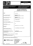
Report Reference #
E213998-A12-UL-1
COVER PAGE FOR TEST REPORT
Product Category:
Product Category CCN:
Test Procedure:
Product:
Model/Type Reference:
Rating(s):
Standards:
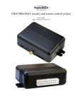
Information Technology Equipment Including Electrical Business Equipment
NWGQ, NWGQ7
Listing
19" Panel PC
W19B89T-XXXX (X can be 0-9, A-Z or blank)
12Vdc, 9.17A
UL 60950-1, 1st Edition, 2006-07-07 (Information Technology Equipment Safety - Part 1: General Requirements)
CSA C22.2 No. 60950-1-03, 1st Edition, 2006-07 (Information Technology
Equipment - Safety - Part 1: General Requirements)
Applicant Name and
Address:
WINMATE COMMUNICATION INC
9TH FL
111-6 HSING TE RD
SUN CHUNG
TAIPEI HSIEN 241 TAIWAN
This Report includes the following parts, in addition to this cover page:
1. Specific Inspection Criteria
2. Specific Technical Criteria
3. Clause Verdicts
4. Critical Components
5. Test Results
6. National Differences
7. Enclosures
Copyright © 2007
Issue Date:
2007-07-09
Page 2 of 2
Report Reference #
E213998-A12-UL-1
This is to certify that representative samples of the products covered by this Test Report have been investigated in accordance with the
above referenced Standards. The products have been found to comply with the requirements covering the category and the products are
judged to be eligible for Follow-Up Service under the indicated Test Procedure. The manufacturer is authorized to use the UL Mark on such
products which comply with this Test Report and any other applicable requirements of Underwriters Laboratories Inc. ('UL') in accordance
with the Follow-Up Service Agreement. Only those products which properly bear the UL Mark are considered as being covered by UL's
Follow-Up Service under the indicated Test Procedure.
The applicant is authorized to reproduce the referenced Test Report provided it is reproduced in its entirety.
Any information and documentation involving UL Mark services are provided on behalf of Underwriters Laboratories Inc. (UL) or any
authorized licensee of UL.
Test Report By:
Reviewed By:
Kevin Hsu
Associate Project Engineer
Underwriters Laboratories Taiwan Co., Ltd.
Stephen Ho
Project Engineer
Underwriters Laboratories Taiwan Co., Ltd.
Copyright © 2007
Issue Date:
2007-07-09
Page 1 of 2
Report Reference #
Enclosure
Test Record
Description
Test Record 1
CRD
Datasheets
Underwriters Laboratories Inc.
E213998-A12-UL-1
Issue Date:
2007-07-09
Page 1 of 2
Report Reference #
E213998-A12-UL-1
Test Record No. 1
--The manufacturer submitted representative production sample of 19" Panel PC, Model W19B89T-XXXX
(X can be 0-9, A-Z or blank) --The results of this investigation indicate that the products evaluated comply
with the applicable requirements in the U.S. and Canadian (Bi-National) Standard for Safety of Information
Technology Equipment-Part 1, Including Electrical Business Equipment, CAN/CSA-C22.2 No. 60950-1-03 *
UL 60950-1 1st Edition, dated April 01, 2003, including revisions through revision date July 7, 2006. --Unless
otherwise noted in the above list of tests, all tests were conducted by Universal Standard Service Inc,
located at Lin Kou Shiang, Taipei Hsien, Taiwan, under the CAP program. --Tests noted by the initials "UL"
were witnessed by UL staff member. --Test results reported relate only to the items tested.
The following tests were conducted:
Test
Testing Location/Comments
End Product Reference Page
General Guidelines
Input: Single-Phase (1.6.2)
Limited Current Circuit Measurement (2.4.1, 2.4.2)
"UL"
Limited Power Source Measurements (2.5)
Loading (4.2.10)
Lithium Battery Reverse Current Measurement (4.3.8)
"UL"
Heating (4.5.1, 1.4.12, 1.4.13)
Abnormal Operation (5.3.1 - 5.3.8.2)
Overload of Operator Accessible Connector (5.3.6)
"UL"
Test results are valid only for the tested equipment. These tests are considered representative of the products
covered by this Test Report. The test methods and results of the above tests have been reviewed and found to
be in accordance with the requirements in the Standard(s) referenced at the beginning of this Test Report.
Underwriters Laboratories Inc.
Issue Date:
2007-07-09
Page 1 of 9
Report Reference #
E213998-A12-UL-1
Enclosure
Photographs
Supplement Id
Description
3-01
Top view
3-02
Rear view
3-03
Internal view
3-04
Connector view
3-05
Top view of Mother Board
3-06
Bottom view of Mother Board
3-07
Top view of Inverter, Taiwan Power Conversion Inc., TI1704WM-03
3-08
Bottom view of Inverter ,Taiwan Power Conversion Inc., TI1704WM-03
Underwriters Laboratories Inc.
Issue Date:
2007-07-09
Page 1 of 7
Report Reference #
E213998-A12-UL-1
Enclosure
Diagrams
Supplement Id
Description
4-01
T1, T2 spec. for inverter (Universal Microelectronics Co., Ltd)
4-02
Alternate T1, T2 spec. for inverter (Biing Jey Enterprise Co., Ltd)
4-03
CE1, CE2 spec. for inverter( Universal Microelectronics Co., Ltd)
4-04
Alternate CE1, CE2 spec. for inverter (Biing Jey Enterprise Co., Ltd)
Underwriters Laboratories Inc.
E213998-A12-UL-1-Diagrams1 (1653x2338x2 tiff)
E213998-A12-UL-1-Diagrams2 (1653x2338x2 tiff)
E213998-A12-UL-1-Diagrams2 (1653x2338x2 tiff) [2]
E213998-A12-UL-1-Diagrams3 (1653x2338x2 tiff)
E213998-A12-UL-1-Diagrams3 (1653x2338x2 tiff) [2]
E213998-A12-UL-1-Diagrams4 (1653x2338x2 tiff)
Issue Date:
2007-07-09
Page 1 of 5
Report Reference #
E213998-A12-UL-1
Enclosure
Schematics + PWB
Supplement Id
5-01
Description
PCB layout of inverter Taiwan Power Conversion Inc., TI1704WM-03
Underwriters Laboratories Inc.
Issue Date:
2007-07-09
Page 1 of 4
Report Reference #
Enclosure
Manuals
Supplement Id
6-01
Description
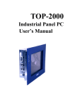
Installation Manual
Underwriters Laboratories Inc.
E213998-A12-UL-1
E213998-A12-UL-1-Manuals1 (1700x2200x2 tiff)
E213998-A12-UL-1-Manuals1 (1700x2200x2 tiff) [2]
E213998-A12-UL-1-Manuals1 (1700x2200x2 tiff) [3]
Issue Date:
2007-07-09
Page 1 of 10
Report Reference #
Enclosure
National Differences
USA / Canada
Underwriters Laboratories Inc.
E213998-A12-UL-1
Issue Date:
2007-07-09
Page 2 of 10
Report Reference #
E213998-A12-UL-1
IEC 60950-1
SubClause Difference + Test
Result - Remark
Verdict
USA / Canada - Differences to IEC 60950-1:2001, First Edition
1.1
Equipment able to be installed in accordance with
the National Electrical Code ANSI/NFPA 70 and the
Canadian Electrical Code, Part1, and when
applicable, the National Electrical Safety Code,
IEEE C2.
Pass
1.1.1
Equipment able to be installed in accordance with
ANSI/NFPA 75 and NEC Art. 645 unless intended
for use outside of computer room and provided with
such instructions.
Pass
1.1.2
Equipment in wire-line communication facilities
serving high-voltage electric power stations
operating at greater than 1kV are excluded.
N/A
1.1.2
Special requirements apply to equipment intended
for use outdoors.
N/A
1.4.14
For Pluggable Equipment Type A, the protection in
the installation is assumed to be 20 A.
N/A
1.5.1
All IEC standards for components identified in
Annex P.1 replaced by the relevant requirements of
CSA and UL component standards in Annex P.1.
Pass
1.5.1
All IEC standards for components identified in
Annex P.2 alternatively satisfied by the relevant
requirements of CSA and UL component standards
in Annex P.2.
Pass
1.5.5
Interconnecting cables acceptable for the
application regarding voltage, current, temperature,
flammability, mechanical serviceability and the like.
Pass
1.5.5
For other than limited power and TNV circuits, the
type of output circuit identified for output connector.
N/A
1.5.5
External cable assemblies that exceed 3.05 m in
length to be types specified in the NEC and CEC.
N/A
1.5.5
Detachable external interconnecting cables 3.05 m
or less in length and provided with equipment
marked to identify the responsible organization and
the designation for the cable.
N/A
1.5.5
Building wiring and cable for use in ducts, plenums There are no any Telephone
and other air handling space subject to special
line and extension cords.
requirements and excluded from scope.
N/A
1.5.5
Telephone line and extension cords and the like
comply with UL 1863 and CSA C22.2 No. 233.
N/A
1.6.1.2
Equipment intended for connection to a d.c. power
(mains) distribution system is subject to special
N/A
Underwriters Laboratories Inc.
Issue Date:
2007-07-09
Page 3 of 10
Report Reference #
E213998-A12-UL-1
IEC 60950-1
SubClause Difference + Test
Result - Remark
Verdict
circuit classification requirements (e.g., TNV-2)
1.6.1.2
Earthing of d.c. powered equipment provided.
N/A
1.7
Lamp replacement information indicated on
lampholder in operator access area.
N/A
1.7.1
Special marking format for equipment intended for
use on a supply system with an earthed neutral and
more than one phase conductor.
N/A
1.7.1
Equipment voltage rating not higher than rating of
the plug except under special conditions.
N/A
1.7.6
Special fuse replacement marking for operator
accessible fuses.
N/A
1.7.7
Identification of terminal connection of the
equipment earthing conductor.
1.7.7
Connectors and field wiring terminals for external
Class 2 or Class 3 circuits provided with marking
indicating minimum Class of wiring to be used.
N/A
1.7.7
Marking located adjacent to terminals and visible
during wiring.
N/A
2.1.1
Screw shell of Edison-base lampholder tied to the
neutral conductor.
N/A
2.1.1.1
No TNV present.
Bare TNV conductive parts in the interior of
equipment normally protected against contact by a
cover intended for occasional removal are exempt
provided instructions include directions for
disconnection of TNV prior to removal of the cover.
N/A
2.3.1.b
Other telecommunication signaling systems (e.g.,
message waiting) than described in 2.3.1(b) are
subject to M.4.
N/A
2.3.1.b
For TNV-2 and TNV-3 circuits with other than
ringing signals and with voltages exceeding 42.4 Vp
or 60 V d.c., the maximum current limit through a
2000 Ohm or greater resistor with loads
disconnected is 7.1 mA peak or 30 mA d.c. under
normal conditions.
N/A
2.3.1.b
Limits for measurements across 5000 ohm resistor
in the event of a single fault are replaced after 200
ms with the limits of M.3.1.4.
N/A
2.3.2
Enamel coating on signal transformer winding wire
allowed as an alternative to Basic insulation in
specific telecommunication applications when
subjected to special construction requirements and
routine testing.
N/A
Class III unit.
Underwriters Laboratories Inc.
N/A
Issue Date:
2007-07-09
Page 4 of 10
Report Reference #
E213998-A12-UL-1
IEC 60950-1
SubClause Difference + Test
Result - Remark
Verdict
2.3.2
In the event of a single fault, the limits of 2.2.3 apply
to SELV circuits and accessible conductive parts.
N/A
2.5
Overcurrent protection device required for Class 2
and Class 3 limiting in accordance with the NEC, or
for a Limited Power Source, not interchangeable
with devices of higher ratings if operator
replaceable.
N/A
2.6
Equipment having receptacles for output a.c. power
connectors generated from an internal separately
derived source have the earthed (grounded) circuit
conductor suitably bonded to earth.
N/A
2.6.3.3
For Pluggable Equipment Type A, if neither a) or b)
are applicable, the current rating of the circuit is
taken as 20 A.
N/A
2.6.3.4
Capacity of connection between earthing terminal
and parts required to be earthed subject to special
conditions based on the current rating of the circuit.
N/A
2.6.3.4
Protective bonding conductors and their terminals of
non-standard constructions (e.g. PWB traces)
evaluated to limited short-circuit test of CSA C22.2
No.0.4.
N/A
2.6.4.1
Field wiring terminals for earthing conductors
suitable for wire sizes (gauge) used in US and
Canada.
N/A
2.7.1
Data for selection of special external branch circuit
overcurrent devices marked on the equipment.
N/A
2.7.1
Standard supply outlets protected by overcurrent
device in accordance with the NEC, and CEC, Part
1.
N/A
2.7.1
Overcurrent protection for individual transformers
that distribute power to other units over branch
circuit wiring.
N/A
2.7.1
Additional requirements for overcurrent protection
apply to equipment provided with panelboards.
N/A
2.7.1
Non-motor-operated equipment requiring special
overcurrent protective device marked with device
rating.
N/A
2.10.5.4
Multi-layer winding wire subject to UL component
wire requirements in addition to 2.10.5.4 and Annex
U.
N/A
3.1.1
Permissible combinations of internal wiring/external
cable sizes for overcurrent and short circuit
N/A
Underwriters Laboratories Inc.
Issue Date:
2007-07-09
Page 5 of 10
Report Reference #
E213998-A12-UL-1
IEC 60950-1
SubClause Difference + Test
Result - Remark
Verdict
protection.
3.1.1
All interconnecting cables protected against
overcurrent and short circuit.
N/A
3.2
Wiring methods permit connection of equipment to
primary power supply in accordance with the NEC
and CEC, Part 1.
N/A
3.2.1
Permitted use for flexible cords and plugs.
N/A
3.2.1
Flexible cords provided with attachment plug rated
125% of equipment current rating.
N/A
3.2.1
Any Class II equipment provided with 15 or 20 A
standard supply outlets, Edison-base lampholders
or single pole disconnect device provided with a
polarized type attachment plug.
N/A
3.2.1.2
Equipment intended for connection to DC mains
supply power systems complies with special wiring
requirements (e.g., no permanent connection to
supply by flexible cord).
N/A
3.2.1.2
Equipment with one pole of the DC mains supply
connected to both the equipment mains input
terminal and the main protective earthing terminal
provided with special instructions and construction
provisions for earthing
N/A
3.2.1.2
Equipment with means for connecting supply to
earthing electrode conductor has no switches or
protective devices between supply connection and
earthing electrode connection.
N/A
3.2.1.2
Special markings and instructions for equipment
with provisions to connect earthed conductor of a
DC supply circuit to earthing conductor at the
equipment.
N/A
3.2.1.2
Special markings and instructions for equipment
with earthed conductor of a DC supply circuit
connected to the earthing conductor at the
equipment.
N/A
3.2.1.2
Terminals and leads provided for permanent
connection of DC powered equipment to supply
marked to indicate polarity if reverse polarity may
result in a hazard.
N/A
3.2.3
Permanently connected equipment has provision for
connecting and securing a field wiring system (i.e.
conduit, or leads etc.) per the NEC and CEC, Part 1.
N/A
3.2.3
Permanently connected equipment may have
N/A
Underwriters Laboratories Inc.
Issue Date:
2007-07-09
Page 6 of 10
Report Reference #
E213998-A12-UL-1
IEC 60950-1
SubClause Difference + Test
Result - Remark
Verdict
terminals or leads not smaller than No. 18 AWG
(0.82 mm²) and not less than 152 mm in length for
connection of field installed wiring.
3.2.3
If supply wires exceed 60 °C, marking indicates use
of 75 °C or 90 °C wiring for supply connection as
appropriate.
N/A
3.2.3
Equipment compatible with suitable trade sizes of
conduits and cables.
N/A
3.2.5
Length of power supply cord limited to between 1.5
and 4.5 m unless shorter length used when intended
for a special installation.
N/A
3.2.5
Conductors in power supply cords sized according
to NEC and CEC, Part I.
N/A
3.2.5
Power supply cords and cord sets incorporate
flexible cords suitable for the particular application.
N/A
3.2.6
Strain relief provided for non-detachable
interconnecting cables not supplied by a limited
power source.
N/A
3.2.9
Adequate wire bending space and volume of field
wiring compartment required to properly make the
field connections.
N/A
3.2.9
Equipment intended solely for installation in
Restricted Access Locations using low voltage d.c.
systems may not need provision for connecting and
securing a field wiring system. A method of securing
wiring or instructions provided to ensure the wiring is
protected from abuse.
N/A
3.3
Field wiring terminals provided for interconnection of
units for other then LPS or Class 2 circuits also
comply with 3.3.
N/A
3.3
Interconnection of units by LPS or Class 2
conductors may have field wiring connectors other
than those specified in 3.3 if wiring is reliably
separated.
N/A
3.3.1
Terminals for the connection of neutral conductor
identified by a distinctive white marking or other
equally effective means.
N/A
3.3.3
Wire binding screw terminal permitted for
connection of No. 10 AWG (5.3 mm²) or smaller
conductor if provided with upturned lugs, cupped
washer or equivalent retention.
N/A
3.3.4
Terminals accept wire sizes (gauge) used in the
N/A
Underwriters Laboratories Inc.
Issue Date:
2007-07-09
Page 7 of 10
Report Reference #
E213998-A12-UL-1
IEC 60950-1
SubClause Difference + Test
Result - Remark
Verdict
U.S. and Canada.
3.3.4
Terminals accept current-carrying conductors rated
125% of the equipment current rating.
N/A
3.3.6
Field wiring terminals marked to indicate the
material(s) of the conductor appropriate for the
terminals used.
N/A
3.3.6
Connection of an aluminum conductor not permitted
to terminal for equipment earthing conductor.
N/A
3.3.6
Field wiring connections made through the use of
suitable pressure connectors (including set screw
type), solder lugs or splices to flexible leads.
N/A
3.4.2
Separate motor control device(s) required for
cord-connected equipment rated more than 12 A, or
with motor rated more than 1/3 hp or more than 120
V.
N/A
3.4.8
Vertically mounted disconnect devices oriented so
up position of handle is "on".
N/A
3.4.11
For computer-room applications, equipment with
battery systems capable of supplying 750 VA for 5
min require battery disconnect means.
N/A
4.2.8.1
Special opening restrictions for enclosures around
CRTs with face dimension of 160 mm or more.
The equipment does not have
any CRT.
N/A
4.2.9
Compartment housing high-pressure lamp marked The equipment does not have
to indicate risk of explosion.
any high pressure lamps.
N/A
4.3.2
Loading test for equipment with handle(s) used to
support more than 9 kg tested at four times the
weight of the unit.
N/A
4.3.6
In addition to the IEC requirements, Direct Plug-in
Equipment complies with UL 1310 or CSA 223
mechanical assembly requirements.
N/A
4.3.12
The maximum quantity of flammable liquid stored in The equipment does not use
equipment complies with ANSI/NFPA 30(Table
any flammable liquids.
NAE.6).
N/A
4.3.12
Equipment using replenishable liquids marked to
indicate type of liquid to be used.
N/A
4.3.13.2
Equipment that produces x-radiation and does not
comply with 4.3.12 under all conditions of servicing
marked to indicate the presence of radiation where
readily visible.
N/A
4.3.13.5
Requirements contained in the applicable national
codes and regulations apply to lasers (21 CFR 1040
N/A
Underwriters Laboratories Inc.
Issue Date:
2007-07-09
Page 8 of 10
Report Reference #
E213998-A12-UL-1
IEC 60950-1
SubClause Difference + Test
Result - Remark
Verdict
and REDR C1370).
4.7
Automated information storage equipment intended
to contain more than 0.76 m³ of combustible media
requires provision for automatic sprinklers or a
gaseous agent extinguishing system.
N/A
4.7.3.1
Equipment for use in environmental air space other
than ducts or plenums provided with metal
enclosure or with non-metallic enclosure having
adequate fire-resistance and low smoke producing
characteristics. Low smoke-producing
characteristics evaluated according to UL 2043.
Equipment for installation in space used for
environmental air as described in Sec. 300-22(c) of
the NEC provided with instructions indicating
suitability for installation in such locations.
N/A
4.7.3.1
Flame spread rating for external surface of
combustible material with exposed area greater
than 0.93 m² or a single dimension greater than 1.8
m; 50 or less for computer room applications or 200
or less for other applications.
N/A
4.7.3.4
Wire marked "VW-1" or "FT-1" considered
equivalent.
5.1.8.2
Special earthing provisions and instructions for
equipment with high touch current due to
telecommunication network connections.
N/A
5.1.8.3
Touch current due to ringing voltage for equipment
containing telecommunication network leads.
N/A
5.3.6
Overloading of SELV connectors and printed wiring (See appended table 5.3)
board receptacles accessible to the operator.
Pass
5.3.6
Tests interrupted by opening of a component
repeated two additional times.
N/A
5.3.8.1
Test interrupted by opening of wire or trace subject
to certain conditions.
N/A
6
Specialized instructions provided for telephones
that may be connected to a telecommunications
network.
6
Marking identifying function of telecommunication
type connectors not used for connection to a
telecommunication network.
N/A
6.2.1
Special requirements for enameled wiring used as
electrical separation provided between parts
N/A
Internal wiring is UL
Recognized, marked VW-1 or
FT-1 and strapped by individual
cable ties (where needed).
No TNV present
Underwriters Laboratories Inc.
Pass
N/A
Issue Date:
2007-07-09
Page 9 of 10
Report Reference #
E213998-A12-UL-1
IEC 60950-1
SubClause Difference + Test
Result - Remark
Verdict
connected to telecommunication network and
telecommunication circuitry intentionally isolated
from network.
6.2.1
Digital line termination equipment (e.g., NCTE)
subject to separation requirements.
N/A
6.3
Equipment remotely powered over
telecommunication wiring systems provided with
specialized markings adjacent to the connection.
N/A
6.3
Overcurrent protection incorporated into equipment
to provide power over telecommunication wiring
system not interchangeable with devices of higher
ratings if operator replaceable.
N/A
6.4
Additional requirements for equipment intended for
connection to a telecommunication network using
cable subject to overvoltage from power line failures
(Fig. 6C).
N/A
6.4
Where 26 AWG line cord required by Fig. 6C, either
the cord is provided with the equipment or described
in the safety instructions.
N/A
6.5
Acoustic pressure from an ear piece less than 136
dBA for short duration disturbances, and less than
125 dBA for handsets, 118 dBA for headsets, and
121 dBA for insert earphones, for long duration
disturbances.
N/A
7
Equipment associated with the cable distribution
system may need to be subjected to applicable
parts of Chapter 8 of the NEC.
N/A
H
Ionizing radiation measurements made under single
fault conditions in accordance with the requirements
of the Code of Federal Regulations 21 CFR 1020
and the Canadian Radiation Emitting Devices Act,
REDR C1370.
N/A
M.2
Continuous ringing signals evaluated to Method A
subjected to special accessibility considerations.
N/A
M.4
Special requirements for message waiting and
similar telecommunications signals.
N/A
NAC
Equipment intended for use with a generic
secondary protector marked with suitable
instructions.
N/A
NAC
Equipment intended for use with a specific primary
or secondary protector marked with suitable
instructions.
N/A
Underwriters Laboratories Inc.
Issue Date:
2007-07-09
Page 10 of 10
Report Reference #
E213998-A12-UL-1
IEC 60950-1
SubClause Difference + Test
Result - Remark
Verdict
NAF
Household/Home Office Document Shredders
N/A
NAF.1.7
Markings and instructions alert the user to key
safety considerations related to use of shredders,
including not intended to be used by children, avoid
touching document feed opening, avoid clothes and
hair entanglement, and avoid aerosol products.
N/A
NAF.2.8.3
Safety interlock cannot be inadvertently activated by
the articulated accessibility probe (figure NAF.1).
N/A
NAF.3.4
Provided with an isolating switch complying with
3.4.2, including 3 mm contact gap, with appropriate
markings associated with the switch.
N/A
NAF.4.4
Hazardous moving parts are not accessible to the
user, as determined using the articulated
accessibility probe (figure NAF.1) and the
accessibility probe/wedge (figures NAF.2/NAF.3).
N/A
Underwriters Laboratories Inc.
Issue Date:
2007-07-09
Page 1 of 45
Report Reference #
E213998-A12-UL-1
SPECIFIC INSPECTION CRITERIA
BA1.0
Special Instructions to UL Representative
BA1.1
N/A
BB1.0
Supporting Documentation
BB1.1
The following documents located at the beginning of this Procedure supplement the requirements
of this Test Report:
A. Authorization - The Authorization page may include additional Factory Identification Code
markings.
B. Generic Inspection Instructions i. Part AC details important information which may be applicable to products covered by this
Procedure. Products described in this Test Report must comply with any applicable items
listed unless otherwise stated in the body of this Test Report.
ii. Part AE details any requirements which may be applicable to all products covered by this
Procedure. Products described in this Test Report must comply with any applicable items
listed unless otherwise stated in the body of each Test Report.
iii. Part AF details the requirements for the UL Certification Mark which is not controlled by the
technical standard used to investigate these products. Products are permitted to bear only
the Certification Mark(s) corresponding to the countries for which it is certified, as indicated
in each Test Report.
BC1.0
Markings and instructions
BC1.1
The following markings and instructions are provided as indicated.
BC1.2
All clause references are from UL 60950-1, 1st Edition, 2006-07-07 (Information Technology
Equipment - Safety - Part 1: General Requirements).
Standard
Clause
Clause Title
Marking or Instruction Details
1.7.1
Power rating Ratings
Ratings (voltage, frequency/dc, current)
Power rating Company
identification
Listee's or Recognized company's name, Trade Name, Trademark or File
Number
Power rating Model
Model Number
1.7.8.3
Symbols Stand-by switch
"Stand-by" to be indicated by
1.7.15
Replaceable
batteries
"CAUTION: Risk of Explosion if Battery is replaced by an Incorrect Type.
Dispose of Used Batteries According to the Instructions."
(60417-2-IEC-5009)
Underwriters Laboratories Inc.
Issue Date:
2007-07-09
Page 2 of 45
Report Reference #
E213998-A12-UL-1
BD1.0
Production-Line Testing Requirements
BD1.1
Electric Strength Test Special Constructions - Refer to Generic Inspection Instructions, Part AC for
further information.
Test
Potential
Model
Component
Removable Parts
Test probe location
V
Test
rms V dc Time, s
N/A
BD1.2
Earthing Continuity Test Exemptions - This
test is not required for the following models:
BD1.3
Electric Strength Test Exemptions - This test is
not required for the following models:
BD1.4
Electric Strength Test Component Exemptions
- The following solid-state components may
disconnected from the remainder of the
circuitry during the performance of this test:
BE1.0
Sample and Test Specifics for Follow-Up Tests at UL
BE1.1
Model
Component
Material
Test
N/A
Underwriters Laboratories Inc.
Sample(s)
Test
Specifics
Issue Date:
2007-07-09
Page 3 of 45
Report Reference #
E213998-A12-UL-1
SPECIFIC TECHNICAL CRITERIA
UL 60950-1, First Edition
Information technology equipment - SafetyPart 1: General Requirements
Report Reference No ........................: E213998-A12-UL-1
Compiled by .....................................: Kevin Hsu
Reviewed by ....................................: Stephen Ho
Date of issue ....................................: 2007-07-09
Standards .........................................: UL 60950-1, 1st Edition, 2006-07-07 (Information Technology
Equipment - Safety - Part 1: General Requirements)
CSA C22.2 No. 60950-1-03, 1st Edition, 2006-07 (Information
Technology Equipment - Safety - Part 1: General Requirements)
Test procedure .................................: Listing
Non-standard test method ...............: N/A
Test item description .......................: 19" Panel PC
Trademark ........................................: None
Model and/or type reference ............: W19B89T-XXXX (X can be 0-9, A-Z or blank)
Rating(s) ...........................................: 12Vdc, 9.17A
Particulars: test item vs. test requirements
Equipment mobility .................................................... : movable
Operating condition ................................................... : continuous
Mains supply tolerance (%) ....................................... : No direct connection
Tested for IT power systems ..................................... : No
IT testing, phase-phase voltage (V) .......................... : N/A
Class of equipment ................................................... : Class III (supplied by SELV)
Mass of equipment (kg) ............................................ : 8.4 kg
Protection against ingress of water ........................... : IP X0
Possible test case verdicts:
- test case does not apply to the test object ............. : N / A
- test object does meet the requirement ................... : Pass
- test object does not meet the requirement ............. : Fail (acceptable only if a corresponding, less stringent
national requirement is "Pass")
Underwriters Laboratories Inc.
Issue Date:
2007-07-09
Page 4 of 45
Report Reference #
General remarks:
- "(see Enclosure #)" refers to additional information appended to the Test Report
- "(see appended table)" refers to a table appended to the Test Report
- Throughout the Test Report a point is used as the decimal separator
Underwriters Laboratories Inc.
E213998-A12-UL-1
Issue Date:
2007-07-09
Page 5 of 45
Report Reference #
E213998-A12-UL-1
GENERAL PRODUCT INFORMATION:
CA1.0
Report Summary
CA1.1
N/A
CB1.0
Product Description
CB1.1
Electronic components mounted on PWB, D/A inverter and LCD panel, and includes with one
HDD, two USB ports, one RS232 port, one RJ-45 port, two 1394 ports, one print port, one DVI port
and two PS2 ports, housed within a metal enclosure.
CC1.0
Model Differences
CC1.1
N/A
CD1.0
Additional Information
CD1.1
N/A
CE1.0
Technical Considerations
CE1.2
The product was submitted and tested for use at the maximum ambient temperature (Tma)
permitted by the manufacturer’s specification of: 40 °C
CE1.3
The means of connection to the mains supply is: Pluggable A or B, Detachable power cord
CE1.8
The following accessible locations (with circuit/schematic designation) are within a limited current
circuit: Secondary side of D/A inverter.
CE1.9
The following circuit locations (with circuit/schematic designation) were investigated as a limited
power source (LPS): USB, 1394 port and PS/2 ports.
CE1.14
The following are available from the Applicant upon request: Installation (Safety) Instructions /
Manual
CE1.15
The power supply in this equipment was: Investigated to an earlier edition/amendment of UL
60950. As part of the investigation of this product, the power supply and its test report were
reviewed and found to comply with UL 60950-1.
Underwriters Laboratories Inc.
Issue Date:
2007-07-09
Page 6 of 45
Report Reference #
E213998-A12-UL-1
IEC 60950-1
Clause
Requirement + Test
Result - Remark
Verdict
1
GENERAL
Pass
1.5
Components
Pass
1.5.1
General
Pass
Comply with IEC 60950 or relevant component
standard
(see appended table 1.5.1)
Pass
1.5.2
Evaluation and testing of components
Components certified to IEC
harmonized standard and
checked for correct
application.
Components not certified are
used in accordance with their
ratings and they comply with
applicable parts of IEC 609501 and the relevant component
Standard.
Components, for which no
relevant IEC-Standard exist,
have been tested under the
conditions occurring in the
equipment, using applicable
parts of IEC 60950-1.
Pass
1.5.3
Thermal controls
There are no thermal controller
used.
N/A
1.5.4
Transformers
1.5.5
Interconnecting cables
1.5.6
Capacitors in primary circuits ................................ :
N/A
1.5.7
Double insulation or reinforced insulation bridged
by components
N/A
1.5.7.1
General
N/A
1.5.7.2
Bridging capacitors
N/A
1.5.7.3
Bridging resistors
N/A
1.5.7.4
Accessible parts
N/A
1.5.8
Components in equipment for IT power systems
N/A
1.6
Power interface
Pass
1.6.1
AC power distribution systems
N/A
Interconnecting cables comply
with the relevant requirements
of this standard.
Class III unit.
Underwriters Laboratories Inc.
Pass
N/A
Issue Date:
2007-07-09
Page 7 of 45
Report Reference #
E213998-A12-UL-1
IEC 60950-1
Clause
Requirement + Test
Result - Remark
Verdict
1.6.2
Input current
(see appended table 1.6.2)
The steady state input current
of the equipment did not
exceed the RATED CURRENT
by more than 10% under
NORMAL LOAD.
Pass
1.6.3
Voltage limit of hand-held equipment
The unit is not a hand-held
equipment.
N/A
1.6.4
Neutral conductor
N/A
Underwriters Laboratories Inc.
Issue Date:
2007-07-09
Page 8 of 45
Report Reference #
E213998-A12-UL-1
IEC 60950-1
Clause
Requirement + Test
Result - Remark
1.7
Marking and instructions
1.7.1
Power rating
Verdict
Pass
Rating marking readily visible
to operator.
Pass
Rated voltage(s) or voltage range(s) (V) ............... : 12 V dc
Pass
Symbol for nature of supply, for d.c. only .............. : IEC 60417 No. 5031 provided
on marking label.
Pass
Rated frequency or rated frequency range (Hz).... : dc
N/A
Rated current (mA or A)......................................... : 9.17 A
Pass
Manufacturer's name or trademark or identification WINMATE COMMUNICATION
mark ....................................................................... : INC
Pass
Type/model or type reference................................ : W19B89T-XXXX (X can be 09, A-Z or blank)
Pass
Symbol for Class II equipment only ....................... :
N/A
Other symbols........................................................ : Additional symbols may be
provided when submitted for
National Approval.
Pass
Certification marks ................................................. : UL, C-UL.
Pass
1.7.2
Safety instructions
Pass
1.7.3
Short duty cycles
N/A
1.7.4
Supply voltage adjustment..................................... :
N/A
1.7.5
Power outlets on the equipment ............................ : No standard power outlets are
provided.
N/A
1.7.6
Fuse identification.................................................. : Evaluated as an element of
power supply certification.
N/A
1.7.7
Wiring terminals
N/A
1.7.7.1
Protective earthing and bonding terminals ............ :
N/A
1.7.7.2
Terminal for a.c. mains supply conductors
N/A
1.7.7.3
Terminals for d.c. mains supply conductors
N/A
1.7.8
Controls and indicators
1.7.8.1
Identification, location and marking ....................... : The function of controls
affecting safety is obvious
regardless of language.
Pass
1.7.8.2
Colours................................................................... : A green LED is illuminated
Pass
Safety instructions in English.
Other languages will be
provided when submitted for
national approval.
See below.
Underwriters Laboratories Inc.
Pass
Issue Date:
2007-07-09
Page 9 of 45
Report Reference #
E213998-A12-UL-1
IEC 60950-1
Clause
Requirement + Test
Result - Remark
Verdict
when the unit is operating.
1.7.8.3
Symbols according to IEC 60417 .......................... : The stand-by switch is marked
with the correct symbol
(60417-1-IEC-5009).
Pass
1.7.8.4
Markings using figures........................................... : Figures are not used for
indicating different positions of
controls.
N/A
1.7.9
Isolation of multiple power sources ....................... :
N/A
1.7.10
IT power distribution systems
N/A
1.7.11
Thermostats and other regulating devices
1.7.12
Language............................................................... : Reviewed only English
markings/instructions.
May be provided in other
languages upon request from
the manufacturer.
1.7.13
Durability
The marking(s) withstood the
required test.
Pass
1.7.14
Removable parts
No marking is located on (a)
removable part(s).
Pass
1.7.15
Replaceable batteries
The required warning is in the
service manual.
Pass
No thermostats or similar
regulating devices.
Language............................................................... : Only English language
reviewed.
May be provided in other
languages upon request from
the manufacturer.
N/A
-
-
1.7.16
Operator access with a tool ................................... : No operator access areas
require the use of a tool.
Pass
1.7.17
Equipment for restricted access locations ............. : Equipment not intended for
installation in a RESTRICTED
ACCESS LOCATION.
N/A
Underwriters Laboratories Inc.
Issue Date:
2007-07-09
Page 10 of 45
Report Reference #
E213998-A12-UL-1
IEC 60950-1
Clause
Requirement + Test
Result - Remark
2
PROTECTION FROM HAZARDS
Pass
2.1
Protection from electric shock and energy hazards
Pass
2.1.1
Protection in operator access areas
Pass
2.1.1.1
Access to energized parts
No operator access parts are
energized parts.
Verdict
Pass
Test by inspection.................................................. : Operator can not contact with
any parts with only basic
insulation to ELV or hazardous
voltage.
Pass
Test with test finger................................................ : The test finger was unable to
contact bare hazardous parts.
Pass
Test with test pin.................................................... : The test pin was unable to
contact bare hazardous parts.
Pass
Test with test probe ............................................... : No TNV present.
N/A
2.1.1.2
Battery compartments............................................ :
N/A
2.1.1.3
Access to ELV wiring
Internal wiring in an ELV circuit
is not user accessible.
Working voltage (V); minimum distance (mm)
through insulation .................................................. :
N/A
-
2.1.1.4
Access to hazardous voltage circuit wiring
No internal wiring accessible to
the user.
2.1.1.5
Energy hazards...................................................... : No energy hazard in operator
access area.
Pass
2.1.1.6
Manual controls
N/A
2.1.1.7
Discharge of capacitors in equipment
The equipment does not
contain any knobs, handles,
levers, or the like.
N/A
Time-constant (s); measured voltage (V) .............. :
2.1.2
Protection in service access areas
2.1.3
Protection in restricted access locations
N/A
No bare parts operating at
HAZARDOUS VOLTAGES in
a service access area.
Underwriters Laboratories Inc.
N/A
N/A
Issue Date:
2007-07-09
Page 11 of 45
Report Reference #
E213998-A12-UL-1
IEC 60950-1
Clause
Requirement + Test
2.2
SELV circuits
2.2.1
General requirements
The unit is supplied by
approved AC adapter. The
SELV reliability were
considered as an element of
certify power adapter.
Pass
2.2.2
Voltages under normal conditions (V) ................... : All accessible voltages are
less than 42.4 Vp or 60 V dc
and are classified as SELV.
Pass
2.2.3
Voltages under fault conditions (V)........................ :
N/A
2.2.3.1
Separation by double insulation or reinforced
insulation (method 1)
N/A
2.2.3.2
Separation by earthed screen (method 2)
N/A
2.2.3.3
Protection by earthing of the SELV circuit (method
3)
N/A
2.2.4
Connection of SELV circuits to other circuits......... : SELV connected to limited
current circuit.
Pass
2.3
TNV circuits
N/A
2.3.1
Limits
2.3.2
2.3.3
Result - Remark
Pass
No TNV circuit.
-
Separation from other circuits and from accessible
parts
N/A
Insulation employed............................................... :
-
Separation from hazardous voltages
Connection of TNV circuits to other circuits
Insulation employed............................................... :
2.3.5
N/A
Type of TNV circuits .............................................. :
Insulation employed............................................... :
2.3.4
Verdict
Test for operating voltages generated externally
Underwriters Laboratories Inc.
N/A
N/A
N/A
Issue Date:
2007-07-09
Page 12 of 45
Report Reference #
E213998-A12-UL-1
IEC 60950-1
Clause
Requirement + Test
Result - Remark
2.4
Limited current circuits
Pass
2.4.1
General requirements
Pass
2.4.2
Limit values
Inverter TI1704WM-03,
manufactured by Taiwan
Power Conversion Inc.,:
Current limit value is 22.18 mA
when min. measured
frequency is 47.4 kHz.
Verdict
Pass
Frequency (Hz) ...................................................... : Inverter TI1704WM-03,
manufactured by Taiwan
Power Conversion Inc.,:
Min. measured 47.4 kHz from
CON2 pin2 to Earth at R15
short.
-
Measured current (mA).......................................... : Inverter TI1704WM-03,
manufactured by Taiwan
Power Conversion Inc.,:
Max. measured 12.5 mA from
CON2 pin2 to Earth when R24
short.
-
Measured voltage (V) ............................................ : 1. Method Part I
Inverter TI1704WM-03,
manufactured by Taiwan
Power Conversion Inc.,:
Max. measured 25.0 Vpk from
CON2 pin2 to Earth when R24
short.
-
2. Method Part II
CON2 pin1 to pin2, normal
consition, Max. measured
1180 Vpk.
Measured capacitance (mF) .................................. : 0.1uF, 118uC.
2.4.3
Connection of limited current circuits to other
circuits
Limited current circuit meets
the limits of 2.4.2 under normal
conditions and under single
component or insulation faults
in interconnected circuits.
Underwriters Laboratories Inc.
Pass
Issue Date:
2007-07-09
Page 13 of 45
Report Reference #
E213998-A12-UL-1
IEC 60950-1
Clause
Requirement + Test
Result - Remark
2.5
Limited power sources
Pass
Inherently limited output
N/A
Impedance limited output
See Table 1.5.1 for PTC
specifications.
Verdict
Pass
For PS2 and 1394 ports:
1. PS2:
Approved PTC Current
Limiters Device(F3) provided,
type SMD1812P110TF,
manufactured by Polytronics
Technology Corp.
2. 1394:
Approved PTC Current
Limiters Device(F4, F5)
provided, type
SMD1812P260TF,
manufactured by Polytronics
Technology Corp.
Overcurrent protective device limited output
For USB port:
Approved Protectors, LowVoltage Solid-State (Q11,
Q47)provided, type
RT9701PBL, manufactured by
Richtek Technology Corp.
Pass
Regulating network limited output under normal
operating and single fault condition
N/A
Regulating network limited output under normal
operating conditions and overcurrent protective
device limited output under single fault condition
N/A
Output voltage (V), output current (A), apparent
USB1 and USB2 port:
power (VA):............................................................ : Uoc=4.99 V, Isc=1.4 max.,
VA=6.41 VA max.
-
PS/2 (Mouse and Keyboard)
port: Uoc=4.99 V, Isc=2.1
max., VA=8.67 VA max.
1394 (CN5 and CN8) port:
Uoc=11.96V, Isc=3.3 max.,
VA=35.60 VA max.
Current rating of overcurrent protective device (A) : protective current 2.2A
Underwriters Laboratories Inc.
-
Issue Date:
2007-07-09
Page 14 of 45
Report Reference #
E213998-A12-UL-1
IEC 60950-1
Clause
Requirement + Test
Result - Remark
2.6
Provisions for earthing and bonding
2.6.1
Protective earthing
2.6.2
Functional earthing
N/A
2.6.3
Protective earthing and protective bonding
conductors
N/A
2.6.3.1
General
N/A
2.6.3.2
Size of protective earthing conductors
N/A
N/A
Class III equipment.
Rated current (A), cross-sectional area (mm2),
AWG ...................................................................... :
2.6.3.3
Verdict
Size of protective bonding conductors
N/A
N/A
Rated current (A), cross-sectional area (mm2),
AWG ...................................................................... :
-
2.6.3.4
Resistance (Ohm) of earthing conductors and their
terminations, test current (A) ................................. :
N/A
2.6.3.5
Colour of insulation ................................................ :
N/A
2.6.4
Terminals
N/A
2.6.4.1
General
N/A
2.6.4.2
Protective earthing and bonding terminals
N/A
Rated current (A), type and nominal thread
diameter (mm) ....................................................... :
-
2.6.4.3
Separation of the protective earthing conductor
from protective bonding conductors
N/A
2.6.5
Integrity of protective earthing
N/A
2.6.5.1
Interconnection of equipment
N/A
2.6.5.2
Components in protective earthing conductors and
protective bonding conductors
N/A
2.6.5.3
Disconnection of protective earth
N/A
2.6.5.4
Parts that can be removed by an operator
N/A
2.6.5.5
Parts removed during servicing
N/A
2.6.5.6
Corrosion resistance
N/A
2.6.5.7
Screws for protective bonding
N/A
2.6.5.8
Reliance on telecommunication network or cable
distribution system
N/A
Underwriters Laboratories Inc.
Issue Date:
2007-07-09
Page 15 of 45
Report Reference #
E213998-A12-UL-1
IEC 60950-1
Clause
Requirement + Test
Result - Remark
2.7
Overcurrent and earth fault protection in primary circuits
N/A
2.7.1
Basic requirements
N/A
Class III equipment.
Verdict
Instructions when protection relies on building
installation
N/A
2.7.2
Faults not covered in 5.3
N/A
2.7.3
Short-circuit backup protection
N/A
2.7.4
Number and location of protective devices............ :
N/A
2.7.5
Protection by several devices
N/A
2.7.6
Warning to service personnel ................................ :
N/A
2.8
Safety interlocks
N/A
2.8.1
General principles
2.8.2
Protection requirements
N/A
2.8.3
Inadvertent reactivation
N/A
2.8.4
Fail-safe operation
N/A
2.8.5
Moving parts
N/A
2.8.6
Overriding
N/A
2.8.7
Switches and relays
N/A
2.8.7.1
Contact gaps (mm) ................................................ :
N/A
2.8.7.2
Overload test
N/A
2.8.7.3
Endurance test
N/A
2.8.7.4
Electric strength test
N/A
2.8.8
Mechanical actuators
N/A
No safety interlock used.
Underwriters Laboratories Inc.
N/A
Issue Date:
2007-07-09
Page 16 of 45
Report Reference #
E213998-A12-UL-1
IEC 60950-1
Clause
Requirement + Test
2.9
Electrical insulation
2.9.1
Properties of insulating materials
2.9.2
Humidity conditioning
2.9.3
Result - Remark
Verdict
Pass
Natural rubber, materials
containing asbestos and
hygroscopic materials are not
used as insulation.
Pass
N/A
Humidity (%) .......................................................... :
-
Temperature (°C)................................................... :
-
Grade of insulation
Function insulation.
Underwriters Laboratories Inc.
Pass
Issue Date:
2007-07-09
Page 17 of 45
Report Reference #
E213998-A12-UL-1
IEC 60950-1
Clause
Requirement + Test
Result - Remark
Verdict
2.10
Clearances, creepage distances and distances through insulation
Pass
2.10.1
General
Pollution degree 2 applicable.
Pass
2.10.2
Determination of working voltage
Class III equipment.
N/A
2.10.3
Clearances
(see appended table 2.10.3
and 2.10.4)
Pass
2.10.3.1
General
See below.
Pass
2.10.3.2
Clearances in primary circuit
2.10.3.3
Clearances in secondary circuits
2.10.3.4
Measurement of transient voltage levels
2.10.4
Creepage distances
N/A
(see appended table 2.10.3
and 2.10.4)
Pass
N/A
(see appended table 2.10.3
and 2.10.4)
CTI tests................................................................. : Material group IIIb; 100 <=CTI
<175.
Pass
-
2.10.5
Solid insulation
N/A
2.10.5.1
Minimum distance through insulation
N/A
2.10.5.2
Thin sheet material
N/A
2.10.5.3
Number of layers (pcs) .......................................... :
-
Electric strength test .............................................. :
-
Printed boards
PWB is not used as reinforced
or supplementary insulation.
Distance through insulation
2.10.5.4
N/A
N/A
Electric strength test for thin sheet insulating
material .................................................................. :
-
Number of layers (pcs) .......................................... :
N/A
Wound components
N/A
Number of layers (pcs) .......................................... :
N/A
Two wires in contact inside wound component;
angle between 45° and 90° ................................... :
N/A
2.10.6
Coated printed boards
No special coating used.
2.10.6.1
General
N/A
2.10.6.2
Sample preparation and preliminary inspection
N/A
2.10.6.3
Thermal cycling
N/A
2.10.6.4
Thermal ageing (°C) .............................................. :
N/A
Underwriters Laboratories Inc.
N/A
Issue Date:
2007-07-09
Page 18 of 45
Report Reference #
E213998-A12-UL-1
IEC 60950-1
Clause
Requirement + Test
Result - Remark
2.10.6.5
Electric strength test .............................................. :
2.10.6.6
Abrasion resistance test
Electric strength test .............................................. :
2.10.7
2.10.8
Verdict
N/A
-
Enclosed and sealed parts .................................... : No hermetically sealed or
enclosed components used.
N/A
Temperature T1=T2 = Tma - Tamb +10K (°C)...... :
N/A
Spacings filled by insulating compound................. :
N/A
Electric strength test .............................................. :
-
2.10.9
Component external terminations
N/A
2.10.10
Insulation with varying dimensions
N/A
Underwriters Laboratories Inc.
Issue Date:
2007-07-09
Page 19 of 45
Report Reference #
E213998-A12-UL-1
IEC 60950-1
Clause
Requirement + Test
3
WIRING, CONNECTIONS AND SUPPLY
Pass
3.1
General
Pass
3.1.1
Current rating and overcurrent protection
All internal wiring used in the
distribution of primary power
protected against over current
were evaluated as an element
of power supply certification.
Pass
3.1.2
Protection against mechanical damage
The wires are routed away
from sharp edges and parts
which could damage
insulation.
Pass
3.1.3
Securing of internal wiring
The wires are positioned in
such a manner that prevents
excessive strain, loosening of
terminal connections and
damage of conductor
insulation.
Pass
3.1.4
Insulation of conductors
3.1.5
Beads and ceramic insulators
The equipment does not have
any beads or similar insulators.
N/A
3.1.6
Screws for electrical contact pressure
The equipment does not have
any screw-type connections.
N/A
3.1.7
Insulating materials in electrical connections
No contact pressure through
insulating material.
Pass
3.1.8
Self-tapping and spaced thread screws
Thread-cutting or space thread
screws are not used for
electrical connections.
Machine screws only.
N/A
3.1.9
Termination of conductors
N/A
10 N pull test
N/A
3.1.10
Sleeving on wiring
Result - Remark
Verdict
N/A
Sleeving is not used as
supplementary insulation.
Underwriters Laboratories Inc.
N/A
Issue Date:
2007-07-09
Page 20 of 45
Report Reference #
E213998-A12-UL-1
IEC 60950-1
Clause
Requirement + Test
Result - Remark
3.2
Connection to an a.c. mains supply or a d.c. mains supply
N/A
3.2.1
Means of connection
N/A
3.2.1.1
Connection to an a.c. mains supply
N/A
3.2.1.2
Connection to a d.c. mains supply
N/A
3.2.2
Multiple supply connections
N/A
3.2.3
Permanently connected equipment
N/A
No direct connection to mains.
Number of conductors, diameter (mm) of cable and
conduits.................................................................. :
Verdict
-
3.2.4
Appliance inlets
N/A
3.2.5
Power supply cords
N/A
3.2.5.1
AC power supply cords
N/A
Type ....................................................................... :
-
Rated current (A), cross-sectional area (mm²),
AWG ...................................................................... :
-
3.2.5.2
DC power supply cords
N/A
3.2.6
Cord anchorages and strain relief
N/A
Mass of equipment (kg), pull (N) ........................... :
-
Longitudinal displacement (mm)............................ :
-
3.2.7
Protection against mechanical damage
N/A
3.2.8
Cord guards
N/A
3.2.9
D (mm); test mass (g) ............................................ :
-
Radius of curvature of cord (mm) .......................... :
-
Supply wiring space
N/A
Underwriters Laboratories Inc.
Issue Date:
2007-07-09
Page 21 of 45
Report Reference #
E213998-A12-UL-1
IEC 60950-1
Clause
Requirement + Test
Result - Remark
3.3
Wiring terminals for connection of external conductors
N/A
3.3.1
Wiring terminals
N/A
3.3.2
Connection of non-detachable power supply cords
N/A
3.3.3
Screw terminals
N/A
3.3.4
Conductor sizes to be connected
N/A
Class III equipment.
Rated current (A), cord/cable type, cross-sectional
area (mm²) ............................................................. :
3.3.5
Verdict
-
Wiring terminal sizes
N/A
Rated current (A), type and nominal thread
diameter (mm) ....................................................... :
-
3.3.6
Wiring terminals design
N/A
3.3.7
Grouping of wiring terminals
N/A
3.3.8
Stranded wire
N/A
3.4
Disconnection from the mains supply
N/A
3.4.1
General requirement
3.4.2
Disconnect devices
N/A
3.4.3
Permanently connected equipment
N/A
3.4.4
Parts which remain energized
N/A
3.4.5
Switches in flexible cords
N/A
3.4.6
Single-phase equipment and d.c. equipment
N/A
3.4.7
Three-phase equipment
N/A
3.4.8
Switches as disconnect devices
N/A
3.4.9
Plugs as disconnect devices
N/A
3.4.10
Interconnected equipment
N/A
3.4.11
Multiple power sources
N/A
Class III equipment.
Underwriters Laboratories Inc.
N/A
Issue Date:
2007-07-09
Page 22 of 45
Report Reference #
E213998-A12-UL-1
IEC 60950-1
Clause
Requirement + Test
Result - Remark
3.5
Interconnection of equipment
Pass
3.5.1
General requirements
Pass
3.5.2
Types of interconnection circuits ........................... : Interconnection circuits are
SELV CIRCUITS.
Pass
3.5.3
ELV circuits as interconnection circuits
N/A
4
PHYSICAL REQUIREMENTS
Pass
4.1
Stability
N/A
Angle of 10°
N/A
Test: force (N)........................................................ :
N/A
4.2
Mechanical strength
Pass
4.2.1
General
4.2.2
Steady force test, 10 N
N/A
4.2.3
Steady force test, 30 N
N/A
4.2.4
Steady force test, 250 N
N/A
4.2.5
Impact test
N/A
Fall test
N/A
Swing test
N/A
4.2.6
Drop test
N/A
4.2.7
Stress relief test
N/A
4.2.8
Cathode ray tubes
Class III equipment.
The equipment does not have
any CRT.
Picture tube separately certified ............................ :
Verdict
N/A
N/A
N/A
4.2.9
High pressure lamps
The equipment does not have
any high pressure lamps.
4.2.10
Wall or ceiling mounted equipment; force (N) ....... : Mounting means withstands
four times unit weight.
Underwriters Laboratories Inc.
N/A
Pass
Issue Date:
2007-07-09
Page 23 of 45
Report Reference #
E213998-A12-UL-1
IEC 60950-1
Clause
Requirement + Test
Result - Remark
Verdict
4.3
Design and construction
4.3.1
Edges and corners
4.3.2
Handles and manual controls; force (N) ................ :
4.3.3
Adjustable controls
The equipment does not have
a voltage selector
N/A
4.3.4
Securing of parts
Electrical and mechanical
connections can be expected
to withstand usual mechanical
stress.
Pass
4.3.5
Connection of plugs and sockets
The equipment does not have
any interchangeable
plugs/sockets.
N/A
4.3.6
Direct plug-in equipment
Not direct plug-in equipment.
N/A
Pass
All edges and corners are
judged to be sufficiently well
rounded so as not to constitute
a hazard.
Pass
N/A
Dimensions (mm) of mains plug for direct plug-in . : Not direct plug-in unit.
N/A
Torque and pull test of mains plug for direct plug-in;
torque (Nm); pull (N) .............................................. :
N/A
4.3.7
Heating elements in earthed equipment
The equipment does not have
any heating elements.
N/A
4.3.8
Batteries
Measured Reverse Current:
please see table 5.3 for detail.
Pass
4.3.9
Oil and grease
The insulation of the internal
wiring is not exposed to oil,
grease, etc.
N/A
4.3.10
Dust, powders, liquids and gases
The equipment does not
produce dust or employ
powders, liquids or gases.
N/A
4.3.11
Containers for liquids or gases
The equipment does not
contain liquids.
N/A
4.3.12
Flammable liquids.................................................. : The equipment does not use
any flammable liquids.
N/A
Quantity of liquid (l)................................................ :
N/A
Flash point (°C)...................................................... :
N/A
4.3.13
Radiation; type of radiation
The equipment does not
generate ionizing radiation or
contain flammable liquids or
gases.
Underwriters Laboratories Inc.
N/A
Issue Date:
2007-07-09
Page 24 of 45
Report Reference #
E213998-A12-UL-1
IEC 60950-1
Clause
Requirement + Test
4.3.13.1
General
N/A
4.3.13.2
Ionizing radiation
N/A
4.3.13.3
Result - Remark
Verdict
Measured radiation (pA/kg) ................................... :
-
Measured high-voltage (kV)................................... :
-
Measured focus voltage (kV) ................................. :
-
CRT markings........................................................ :
-
Effect of ultraviolet (UV) radiation on materials
N/A
Part, property, retention after test, flammability
classification .......................................................... :
N/A
4.3.13.4
Human exposure to ultraviolet (UV) radiation........ :
N/A
4.3.13.5
Laser (including LEDs)
N/A
Laser class............................................................. :
-
4.3.13.6
Other types ............................................................ :
N/A
4.4
Protection against hazardous moving parts
N/A
4.4.1
General
N/A
4.4.2
Protection in operator access areas
N/A
4.4.3
Protection in restricted access locations
N/A
4.4.4
Protection in service access areas
N/A
4.5
Thermal requirements
Pass
4.5.1
Maximum temperatures
4.5.2
The equipment and its
component parts did not attain
excessive temperatures during
normal operation.
Pass
Normal load condition per Annex L ....................... : Operated in the most
unfavorable way of operation
given in the operating
instructions until steady
conditions established.
(see appended table 4.5)
Pass
Resistance to abnormal heat
N/A
Underwriters Laboratories Inc.
Issue Date:
2007-07-09
Page 25 of 45
Report Reference #
E213998-A12-UL-1
IEC 60950-1
Clause
Requirement + Test
Result - Remark
4.6
Openings in enclosures
4.6.1
Top and side openings
Pass
Openings do not exceed 5 mm
in any dimension.
Dimensions (mm)................................................... : 1.Topside (Two opening area):
Cover area is 15.6 by 27.4 mm
max., each circle opening is
3.4 mm max.
2.Rear side: Cover area is
60.65 by 60.65 mm max., each
circle opening is 4.2 mm max.
3. Opening for DC Fan: Cover
area is 39 by 39 mm max.,
each slot opening is 4.05 by
12.3 mm max.
4. Mounting Holes: See
Manuals 6-01 for details.
4.6.2
Bottoms of fire enclosures
Verdict
No openings.
Construction of the bottom..................................... : See 4.6.1 for details.
Pass
-
Pass
-
4.6.3
Doors or covers in fire enclosures
The equipment does not have
any doors or covers.
N/A
4.6.4
Openings in transportable equipment
Unit not transportable.
N/A
4.6.5
Adhesives for constructional purposes
Adhesives not used for
securement of internal barriers
or screens.
N/A
Conditioning temperature (°C)/time (weeks) ......... :
Underwriters Laboratories Inc.
-
Issue Date:
2007-07-09
Page 26 of 45
Report Reference #
E213998-A12-UL-1
IEC 60950-1
Clause
Requirement + Test
Result - Remark
4.7
Resistance to fire
4.7.1
Reducing the risk of ignition and spread of flame
Verdict
Pass
Method 1: Selection and
application of components and
materials which minimize the
possibility of ignition and
spread of flame.
Pass
Method 1, selection and application of components
wiring and materials
Pass
Method 2, application of all of simulated fault
condition tests
N/A
4.7.2
Conditions for a fire enclosure
Pass
4.7.2.1
Parts requiring a fire enclosure
4.7.2.2
Parts not requiring a fire enclosure
N/A
4.7.3
Materials
Pass
4.7.3.1
General
See below.
Pass
4.7.3.2
Materials for fire enclosures
The fire enclosure is metal.
Pass
4.7.3.3
Materials for components and other parts outside
fire enclosures
Connectors are made of
materials of Class V-2
minimum.
Pass
4.7.3.4
Materials for components and other parts inside fire PWBs are rated min. V-1.
enclosures
All internal materials are rated
V-2 or better or are mounted
on a PWB rated V-1 or better
Internal wiring is UL
Recognized, marked VW-1 or
FT-1 and strapped by
individual cable ties (where
needed).
See Table 1.5.1 for material
information.
Pass
4.7.3.5
Materials for air filter assemblies
The equipment does not have
any air filters.
N/A
4.7.3.6
Materials used in high-voltage components
No high-voltage components.
N/A
A fire enclosure covers all
parts.
Underwriters Laboratories Inc.
Pass
Issue Date:
2007-07-09
Page 27 of 45
Report Reference #
E213998-A12-UL-1
IEC 60950-1
Clause
Requirement + Test
Result - Remark
Verdict
5
ELECTRICAL REQUIREMENTS AND SIMULATED ABNORMAL CONDITIONS
Pass
5.1
Touch current and protective conductor current
N/A
5.1.1
General
N/A
5.1.2
Equipment under test (EUT)
N/A
5.1.3
Test circuit
N/A
5.1.4
Application of measuring instrument
N/A
5.1.5
Test procedure
N/A
5.1.6
Test measurements
N/A
Test voltage (V) ..................................................... :
-
Measured touch current (mA) ................................ :
-
Max. allowed touch current (mA)........................... :
-
Measured protective conductor current (mA) ........ :
-
Max. allowed protective conductor current (mA) ... :
-
5.1.7
Equipment with touch current exceeding 3.5 mA .. :
N/A
5.1.8
Touch currents to and from telecommunication
networks and cable distribution systems and from
telecommunication networks
N/A
5.1.8.1
Limitation of the touch current to a
telecommunication network and a cable distribution
system
N/A
Test voltage (V) ..................................................... :
-
Measured touch current (mA) ................................ :
-
Max. allowed touch current (mA)........................... :
-
5.1.8.2
Summation of touch currents from
telecommunication networks ................................. :
N/A
5.2
Electric strength
N/A
5.2.1
General
5.2.2
Test procedure
Class III unit.
N/A
N/A
Underwriters Laboratories Inc.
Issue Date:
2007-07-09
Page 28 of 45
Report Reference #
E213998-A12-UL-1
IEC 60950-1
Clause
Requirement + Test
5.3
Abnormal operating and fault conditions
5.3.1
Protection against overload and abnormal
operation
5.3.2
Motors
5.3.3
Transformers
5.3.4
Functional insulation .............................................. : Functional insulation complies
with the requirements (a), (b),
or (c).
Pass
5.3.5
Electromechanical components
The equipment does not have
any electromechanical
components in the secondary.
N/A
5.3.6
Simulation of faults
(See appended table 5.3)
Pass
5.3.7
Unattended equipment
Equipment is not intended for
unattended use.
N/A
5.3.8
Compliance criteria for abnormal operating and
fault conditions
No fire, emission of molten
metal or deformation was
noted during the tests.
Pass
6
CONNECTION TO TELECOMMUNICATION NETWORKS
N/A
6.1
Protection of telecommunication network service persons, and users of other
equipment connected to the network, from hazards in the equipment
N/A
6.1.1
Protection from hazardous voltages
N/A
6.1.2
Separation of the telecommunication network from earth
N/A
6.1.2.1
Requirements
N/A
6.1.2.2
Result - Remark
Verdict
Pass
See below.
Pass
N/A
Evaluated as part of power
supply.
N/A
Test voltage (V) ..................................................... :
-
Current in the test circuit (mA) ............................... :
-
Exclusions.............................................................. :
N/A
Underwriters Laboratories Inc.
Issue Date:
2007-07-09
Page 29 of 45
Report Reference #
E213998-A12-UL-1
IEC 60950-1
Clause
Requirement + Test
Result - Remark
Verdict
6.2
Protection of equipment users from overvoltages on telecommunication
networks
N/A
6.2.1
Separation requirements
N/A
6.2.2
Electric strength test procedure
N/A
6.2.2.1
Impulse test
N/A
6.2.2.2
Steady-state test
N/A
6.2.2.3
Compliance criteria
N/A
6.3
Protection of the telecommunication wiring system from overheating
N/A
Max. output current (A) .......................................... :
-
Current limiting method.......................................... :
-
7
CONNECTION TO CABLE DISTRIBUTION SYSTEMS
N/A
7.1
Protection of cable distribution system service persons, and users of other
equipment connected to the system, from hazardous voltages in the equipment
N/A
7.2
Protection of equipment users from overvoltages
on the cable distribution system
N/A
7.3
Insulation between primary circuits and cable
distribution systems
N/A
7.3.1
General
N/A
7.3.2
Voltage surge test
N/A
7.3.3
Impulse test
N/A
Underwriters Laboratories Inc.
Issue Date:
2007-07-09
Page 30 of 45
Report Reference #
E213998-A12-UL-1
IEC 60950-1
Clause
Requirement + Test
Result - Remark
Verdict
A
Annex A, TESTS FOR RESISTANCE TO HEAT AND FIRE
N/A
A.1
Flammability test for fire enclosures of movable equipment having a total mass
exceeding 18 kg, and of stationary equipment (see 4.7.3.2)
N/A
A.1.1
Samples ................................................................. :
-
Wall thickness (mm) .............................................. :
-
A.1.2
Conditioning of samples; temperature (°C) ........... :
N/A
A.1.3
Mounting of samples.............................................. :
N/A
A.1.4
Test flame
N/A
A.1.5
Test procedure
N/A
A.1.6
Compliance criteria
N/A
Sample 1 burning time (s)...................................... :
-
Sample 2 burning time (s)...................................... :
-
Sample 3 burning time (s)...................................... :
-
Underwriters Laboratories Inc.
Issue Date:
2007-07-09
Page 31 of 45
Report Reference #
E213998-A12-UL-1
IEC 60950-1
Clause
Requirement + Test
Result - Remark
Verdict
A.2
Flammability test for fire enclosures of movable equipment having a total
mass not exceeding 18 kg, and for material and components located inside
fire enclosures (see 4.7.3.2 and 4.7.3.4)
A.2.1
Samples, material .................................................. :
-
Wall thickness (mm) .............................................. :
-
N/A
A.2.2
Conditioning of samples
N/A
A.2.3
Mounting of samples
N/A
A.2.4
Test flame
N/A
A.2.5
Test procedure
N/A
A.2.6
Compliance criteria
N/A
A.2.7
Sample 1 burning time (s)...................................... :
-
Sample 2 burning time (s)...................................... :
-
Sample 3 burning time (s)...................................... :
-
Alternative test acc. to IEC 60695-2-2, cl. 4, 8
N/A
Sample 1 burning time (s)...................................... :
-
Sample 2 burning time (s)...................................... :
-
Sample 3 burning time (s)...................................... :
-
A.3
Hot flaming oil test (see 4.6.2)
N/A
A.3.1
Mounting of samples
N/A
A.3.2
Test procedure
N/A
A.3.3
Compliance criterion
N/A
Underwriters Laboratories Inc.
Issue Date:
2007-07-09
Page 32 of 45
Report Reference #
E213998-A12-UL-1
IEC 60950-1
Clause
Requirement + Test
Result - Remark
Verdict
B
Annex B, MOTOR TESTS UNDER ABNORMAL CONDITIONS(see 4.7.2.2 and
5.3.2)
N/A
B.1
General requirements
N/A
Position .................................................................. :
-
Manufacturer.......................................................... :
-
Type ....................................................................... :
-
Rated values.......................................................... :
-
B.2
Test conditions
N/A
B.3
Maximum temperatures
N/A
B.4
Running overload test
N/A
B.5
Locked-rotor overload test
N/A
Test duration (days)............................................... :
-
Electric strength test: test voltage (V).................... :
-
B.6
Running overload test for d.c. motors in secondary
circuits
N/A
B.7
Locked-rotor overload test for d.c. motors in secondary circuits
N/A
B.7.1
Test procedure
N/A
B.7.2
Alternative test procedure; test time (h)................. :
N/A
B.7.3
Electric strength test
N/A
B.8
Test for motors with capacitors
N/A
B.9
Test for three-phase motors
N/A
B.10
Test for series motors
N/A
Operating voltage (V)............................................. :
Underwriters Laboratories Inc.
-
Issue Date:
2007-07-09
Page 33 of 45
Report Reference #
E213998-A12-UL-1
IEC 60950-1
Clause
Requirement + Test
Result - Remark
Verdict
C
Annex C, TRANSFORMERS (see 1.5.4 and 5.3.3)
N/A
Position .................................................................. :
-
Manufacturer.......................................................... :
-
Type ....................................................................... :
-
Rated values.......................................................... :
-
Method of protection .............................................. :
-
C.1
Overload test
N/A
C.2
Insulation
N/A
Protection from displacement of windings ............. :
N/A
D
Annex D, MEASURING INSTRUMENTS FOR TOUCH-CURRENT TESTS
N/A
D.1
Measuring instrument
N/A
D.2
Alternative measuring instrument
N/A
E
Annex E, TEMPERATURE RISE OF A WINDING
N/A
F
Annex F, MEASUREMENT OF CLEARANCES AND CREEPAGE DISTANCES
(see 2.10)
Pass
Underwriters Laboratories Inc.
Issue Date:
2007-07-09
Page 34 of 45
Report Reference #
E213998-A12-UL-1
IEC 60950-1
Clause
Requirement + Test
Result - Remark
G
Annex G, ALTERNATIVE METHOD FOR DETERMINING MINIMUM
CLEARANCES
N/A
G.1
Summary of the procedure for determining
minimum clearances
N/A
G.2
Determination of mains transient voltage (V)
N/A
G.2.1
AC mains supply
N/A
G.2.2
DC mains supply
N/A
G.3
Determination of telecommunication network
transient voltage (V) :............................................. :
N/A
G.4
Determination of required withstand voltage (V) ... :
N/A
G.5
Measurement of transient levels (V)...................... :
N/A
G.6
Determination of minimum clearances .................. :
N/A
H
ANNEX H, IONIZING RADIATION (see 4.3.13)
N/A
J
Annex J, TABLE OF ELECTROCHEMICAL POTENTIALS (see 2.6.5.6)
N/A
Metal used ............................................................. :
Verdict
-
K
ANNEX K, THERMAL CONTROLS (see 1.5.3 and 5.3.7)
N/A
K.1
Making and breaking capacity
N/A
K.2
Thermostat reliability; operating voltage (V) .......... :
N/A
K.3
Thermostat endurance test; operating voltage (V) :
N/A
K.4
Temperature limiter endurance; operating voltage
(V) .......................................................................... :
N/A
K.5
Thermal cut-out reliability
N/A
K.6
Stability of operation
N/A
Underwriters Laboratories Inc.
Issue Date:
2007-07-09
Page 35 of 45
Report Reference #
E213998-A12-UL-1
IEC 60950-1
Clause
Requirement + Test
Result - Remark
L
Annex L, NORMAL LOAD CONDITIONS FOR SOME TYPES OF ELECTRICAL
BUSINESS EQUIPMENT (see 1.2.2.1 and 4.5.1)
Pass
L.1
Typewriters
N/A
L.2
Adding machines and cash registers
N/A
L.3
Erasers
N/A
L.4
Pencil sharpeners
N/A
L.5
Duplicators and copy machines
N/A
L.6
Motor-operated files
N/A
L.7
Other business equipment
Pass
M
Annex M, CRITERIA FOR TELEPHONE RINGING SIGNALS (see 2.3.1)
N/A
M.1
Introduction
N/A
M.2
Method A
N/A
M.3
Method B
N/A
M.3.1
Ringing signal
N/A
M.3.1.1
Frequency (Hz) ...................................................... :
-
M.3.1.2
Voltage (V)............................................................. :
-
M.3.1.3
Cadence; time (s), voltage (V)............................... :
-
M.3.1.4
Single fault current (mA) ........................................ :
-
M.3.2
Tripping device and monitoring voltage................. :
N/A
M.3.2.1
Conditions for use of a tripping device or a
monitoring voltage
N/A
M.3.2.2
Tripping device
N/A
M.3.2.3
Monitoring voltage (V)............................................ :
N/A
N
Annex N, IMPULSE TEST GENERATORS (see 2.10.3.4, 6.2.2.1, 7.3.2 and
clause G.5)
N/A
N.1
ITU-T impulse test generators
N/A
N.2
IEC 60065 impulse test generator
N/A
Underwriters Laboratories Inc.
Verdict
Issue Date:
2007-07-09
Page 36 of 45
Report Reference #
E213998-A12-UL-1
IEC 60950-1
Clause
Requirement + Test
Result - Remark
P
Annex P, NORMATIVE REFERENCES
Pass
Q
Annex Q, BIBLIOGRAPHY
Pass
R
Annex R, EXAMPLES OF REQUIREMENTS FOR QUALITY CONTROL
PROGRAMMES
N/A
R.1
Minimum separation distances for unpopulated
coated printed boards (see 2.10.6)
N/A
R.2
Reduced clearances (see 2.10.3)
N/A
S
Annex S, PROCEDURE FOR IMPULSE TESTING (see 6.2.2.3)
N/A
S.1
Test equipment
N/A
S.2
Test procedure
N/A
S.3
Examples of waveforms during impulse testing
N/A
T
Annex T, GUIDANCE ON PROTECTION AGAINST INGRESS OF WATER (see
1.1.2)
N/A
............................................................................... :
U
Annex U, INSULATED WINDING WIRES FOR USE WITHOUT INTERLEAVED
INSULATION (see 2.10.5.4)
............................................................................... :
Underwriters Laboratories Inc.
Verdict
-
N/A
-
Issue Date:
2007-07-09
Page 37 of 45
Report Reference #
E213998-A12-UL-1
IEC 60950-1
Clause
Requirement + Test
Result - Remark
Verdict
1.5.1
TABLE: list of critical components
Object/part No.
Manufacturer/
trademark
type/model
technical data
Product Category
CCN(s)
01. Switching adapter
Li-Shin International
Enterprise Corp.
Various
0227B12110
QQGQ
Various
AVLV2
UL
03. Label
Various
Various
PGDQ2 or PGJI2
UL
04. Wiring, internal
secondary ELV/SELV
circuits
Various
Various
AVLV2
UL
05. Connectors and
Receptacles (secondary
ELV/SELV circuits)
06. Insulating
Tubing/Sleeving
--
--
I/p:100-240V, 2.0A, 50-60Hz
O/p:12V, 9.17A,
Min. 80 degree C, 30V, max
3.05 m long, jacketed, VW-1 or
FT-1
Min. 50 degree C, if maximum
surface temperature not
specified.
FEP, PTFE, PVC, TFE,
neoprene, polyimide or marked
VW-1, jacketed, min 30V, 80
degree C
Copper alloy pins housed in
bodies of plastic rated V-2 min.
Required
Marks of
Conformity
UL
QMFZ2, ECBT2,
RTRT2, DUXR2
UL
Various
Various
UZFT2, YDPU2,
YDTU2
UL
3-03
07. Enclosure
--
--
--
3-01
08.LCD Panel
09. Speaker (x2)
10. DC Fan
(for
system)
10-01. DC Fan ( for
CPU)
11. HDD
12. D/A Inverter
Various
-Evercool Thermal
Co., Ltd
Minebea-Matsushita
Motor Corp
Various
Taiwan Power
--GPWV2
--UL
3-01
3-03
GPWV2
UL
NWGQ2
--
UL
--
02. Interconnecting
Cable (optional)
Pass
FEP, PTFE, PVC, TFE,
neoprene, polyimide or marked
VW-1; 105 degree C, 300V.
-Metal min. thickness 0.95 mm
min. Total overall 480 by 330
by 91 mm max.
Various
19", TFT Type
-8 ohm, 3.0W max.
EC4020L12BA
12Vdc, 0.06A max., 4.97 CFM
min.
1604KL-04W-B49 12Vdc, 0.10A max., 4.95 CFM
min.
Various
5V/12V, 1.5A/2.0A max.
TI1704WM-03
I/P: 13.2Vdc max., 2.5A; O/P:
Underwriters Laboratories Inc.
Supplement ID
3-03
3-07
Issue Date:
2007-07-09
Page 38 of 45
Report Reference #
E213998-A12-UL-1
IEC 60950-1
Clause
Requirement + Test
12-A. Transformer (T1,
T2)
12-A-01. Core for D/A
Inverter Transformer
12-A-02. Bobbin for D/A
Inverter Transformer
Result - Remark
Conversion Inc.
LKW9R801006U
Universal
Microelectronics Co.,
Ltd
--Various
Various
12-A-03. Wire for D/A
Inverter Transformer
12-B. Transformer (T1,
T2)
(alternate)
12-B-01. Core for D/A
Inverter Transformer
12-B-02. Bobbin for D/A
Inverter Transformer
Various
Various
Biing Jey Enterprise
Co., Ltd
--
LTL19010609B
--
Various
Various
12-B-03. Wire for D/A
Inverter Transformer
12-C Transformer (CE1,
CE2)
Various
Various
12-C-01. Core for D/A
Inverter Transformer
12-C-02. Bobbin for D/A
Inverter Transformer
12-C-03. Wire for D/A
Inverter Transformer
12-D Transformer (CE1,
LTL19010609U
Universal
Microelectronics Co.,
Ltd
--Various
Various
Various
Various
Biing Jey Enterprise
LKW9R801006B
Underwriters Laboratories Inc.
Verdict
760Vrms max., 8.0mArms max.
105 degree C
--
Ferrite, Overall 27.7 by 20 by
7.85 mm
Liquid Crystal Polymer (L.C.P.),
rated V-2 min., min. thickness
0.3 mm or Phenolic, min. 0.71
mm
Copper magnet wire, 180
degree C min.
105 degree C
Ferrite, Overall 27.7 by 20 by
7.85 mm
Liquid Crystal Polymer (L.C.P.),
rated V-2 min., min. thickness
0.3 mm or Phenolic, min. 0.71
mm
Copper magnet wire, 105
degree C min.
105 degreeC
Ferrite, Overall 16.96 by 13 by
6.47 mm
Liquid Crystal Polymer (L.C.P.),
rated V-2 min., min. thickness
0.3 mm or Phenolic, min. 0.71
mm
Copper magnet wire, 105
degree C min.
105 degree C
--
--
--
QMFZ2
UL
OBMW2
UL
--
--
--
--
QMFZ2
UL/CUL
OBMW2
UL
--
--
--
--
QMFZ2
UL
OBMW2
UL
--
--
4-01
4-02
4-03
4-04
Issue Date:
2007-07-09
Page 39 of 45
Report Reference #
E213998-A12-UL-1
IEC 60950-1
Clause
Requirement + Test
Result - Remark
CE2)(Alternate)
12-D-01. Core for D/A
Inverter Transformer
12-D-02. Bobbin for D/A
Inverter Transformer
Co., Ltd
--
--
Various
Various
12-D-03. Wire for D/A
Inverter Transformer
13. Capacity (C15, C17)
14. Mother board
Various
Various
Various
iBase Technology
Inc.
Sony Energy Devices
Corporation
Richtek Technology
Corp.
Polytronics
Technology Corp.
Polytronics
Technology Corp.
Various
MB890
Various
14-01. RTC Battery
14-02. USB Protective
Device (Q47, Q11)
14-03. PTC Polyswitch
for PS/2 ports use (F3)
14-04. PTC Polyswitch
for 1394 ports use (F4,
F5)
15.All PWBs
Verdict
--
--
QMFZ2
UL
OBMW2
UL
---
---
BBCV2
UL
QVGS2
UL
SMD1812P110TF 8V, Ih=1.1A It=2.2, CA=3
XGPU2
UL
SMD1812P260TF 8V, Ih=2.6A It=5.2, CA=3
XGPU2
UL
Various
ZPMV2
UL
CR2032
RT9701PBL
Underwriters Laboratories Inc.
Ferrite, Overall 16.96 by 13 by
6.47 mm
Liquid Crystal Polymer (L.C.P.),
rated V-2 min., min. thickness
0.3 mm or Phenolic, min. 0.71
mm
Copper magnet wire, 105
degree C min.
10pF, 3KV
-3V, 220mAh max. abnormal
charging current 12mA
2.2-6 Vdc, 2.2A.
V-1 min. 105 degree C
3-05
3-03
Issue Date:
2007-07-09
Page 40 of 45
Report Reference #
E213998-A12-UL-1
IEC 60950-1
Clause
Requirement + Test
1.6.2
TABLE: electrical data (in normal conditions)
fuse #
--
I rated (A)
U (V)
9.17
12Vdc
Result - Remark
P (W)
65.76
I (mA)
5480
Verdict
Pass
I fuse (mA) condition/status
-Maximum normal load
supplementary information:
Maximum normal load was defined as follows: Reading and writing in HDD, playing music, and each USB ports
loaded 2.5W with Max. contrast and brightness, display normally.
2.10.3 and
2.10.4
Pass
TABLE: clearance and creepage distance measurements
clearance cl and creepage
distance dcr at/of:
--
Up
(V)
--
U r.m.s. (V) required cl
cl (mm)
(mm)
----
required
dcr (mm)
--
dcr
(mm)
--
supplementary information:
All circuits are SELV, only functional insulation required.
2.10.5
N/A
TABLE: distance through insulation measurements
distance through insulation di at/of:
Up
(V)
test voltage (V)
required di
(mm)
di
(mm)
supplementary information:
4.5
TABLE: temperature rise measurements
-test voltage (V) ......................................... See
below
-t1 (°C)........................................................ -t2 (°C)........................................................ --
--
Pass
--
--
--
—
--
--
--
—
--
--
--
—
maximum temperature T of part/at:
T (°C)
19'' Panel PC model: W19B89T-XXXX Adapter -Model: LI SHIN/0227B12110
Normal Condition
Condi
tion 1
(Origi
nal)
--
--
--
allowed
Tmax (°C)
--
Conditio -n1
(Shift to
40)
--
--
--
--
Underwriters Laboratories Inc.
Issue Date:
2007-07-09
Page 41 of 45
Report Reference #
E213998-A12-UL-1
IEC 60950-1
Clause
Requirement + Test
Result - Remark
1.Ambient
2.T1 coil
3.CE1 coil
4.PWB near CPU
5.RTC Body
6.CPU fan
7.System fan
7.HDD body
8.Enclosure outside near CPU
23.8
70.6
52.1
48.0
44.7
38.2
41.7
48.9
33.5
temperature T of winding:
40.0
86.8
68.3
64.2
60.9
54.4
57.9
65.1
49.7
---------R2 ( Ω)
R1 (Ω)
--
--
----------
--
T (°C)
--
Verdict
----------
-105
105
105
100
105
105
-70
allowed
insulation
Tmax (°C)
class
---
supplementary information:
The temperatures were measured under worst case normal mode defined in 1.2.2.1 and as described in 1.6.1
at voltages as described in 1.4.5.
With a specified ambient temperature of 40 degree C, the max. temperature is calculated as follows:
Components with:
- max. absolute temp. of 100 degree C (RTC) Tmax(degree C) = 100 degree C
- max. absolute temp. of 105 degree C (PWB, CE1, T1) Tmax(degree C) = 105 degree C
- when no class of insulation is given, min. insulation 105 degree C assumed.
User accessible area:
- material is Metal (70 degree C)
4.5.2
Tmax(degree C)= 70 degree C
N/A
TABLE: ball pressure test of thermoplastics
allowed impression diameter (mm) ........................ :
part
—
test temperature (°C)
impression diameter
(mm)
supplementary information:
4.7
TABLE: resistance to fire
part
--
Pass
manufacturer of material
--
type of material
--
supplementary information:
Please see Table 1.5.1
Underwriters Laboratories Inc.
thickness(mm)
--
flammability
class
--
Issue Date:
2007-07-09
Page 42 of 45
Report Reference #
E213998-A12-UL-1
IEC 60950-1
Clause
5.2
Requirement + Test
Result - Remark
Verdict
TABLE: electric strength tests, impulse tests and voltage surge tests
test voltage applied between:
test voltage (V)
a.c./d.c.
N/A
breakdown
Yes / No
supplementary information:
5.3
Pass
TABLE: fault condition tests
ambient temperature (°C) ....................................... : See below
model/type of power supply.................................... : -manufacturer of power supply ................................ : --
—
rated markings of power supply ............................. : --
⎯
component fault
No.
---
test voltage
(V)
--
--
--
RTC
battery
reverse
current test
RTC
battery
reverse
current test
D10 (1-2)
RTC
battery
reverse
current test
D10 (2-3)
RTC
battery
reverse
current test
R273
--
test time
fuse current
(A)
—
—
--
fuse
No.
--
--
--
--
--
--
Normal
12Vdc
--
--
--
4.3.8 Lithium battery
reverse current
measurement test
19" Panel PC model:
W19B89T-XXXX
Motherboard model: iBase
Technology Inc./MB890
Charging current is 0.1mA
Short
12Vdc
--
--
--
Charging current is 3.3mA
Short
12Vdc
--
--
--
Charging current is 2.9mA
Short
12Vdc
--
--
--
Charging current is 0.1mA
--
--
--
--
--
5.3.1-5.3.8.2 ABNORMAL
Underwriters Laboratories Inc.
result
Issue Date:
2007-07-09
Page 43 of 45
Report Reference #
E213998-A12-UL-1
IEC 60950-1
Clause
--
Requirement + Test
--
--
--
--
System fan Blocked
12Vdc
2hrs.
29mins.
--
5.48
CPU fan
Stalled
12Vdc
2hrs
21mins.
--
5.48
Ventilation
openings
Blocked
12Vdc
1hrs.
44mins.
--
5.48
--
--
--
--
--
--
--
--
--
--
--
--
USB1
(CN6)
Pin1
Overload
12Vdc
1hrs
--
--
USB1
(CN6)
pin2~4
Overload
12Vdc
--
--
--
USB2
(CN6) pin5
Overload
12Vdc
1hrs
--
--
USB2(CN6 Overload
)
pin6~8
12Vdc
--
--
--
Overload
12Vdc
1hrs
--
--
1394
port(CN5)
pin1
--
Result - Remark
Underwriters Laboratories Inc.
Verdict
OPERATION TESTS
19" Panel PC model:
W19B89T-XXXX
Adapter model: LI
SHIN/0225B12110
NT.NC.CT. Normal
operation. No hazardous.
Maximum Temp: T1
coil=96.4 *C
Ambient=40.0*C.
NT, NC, CT, Normal
operation. No hazardous.
Maximum Temp: T1
coil=90.7 *C
Ambient=40.0*C.
NT, NC, CT. Normal
operation. No hazardous.
Maximum Temp: T1
coil=98.2 *C
Ambient=40.0*C.
5.3.6 Overload of operator
accessible connector test:
19" Panel PC model:
W19B89T-XXXX
Motherboard model: iBase
Technology Inc./MB890
NB, NC, NT
Open circuit
voltage=4.99Vdc
Maximum available current
=1100mA
C
Open circuit voltage=0Vdc
Maximum available current
=0mA
NB, NC, NT
Open circuit
voltage=4.99Vdc
Maximum available current
=1100mA
C
Open circuit voltage=0Vdc
Maximum available current
=0mA
NB,NC,NT
Open circuit
voltage=11.96Vdc
Maximum available current
Issue Date:
2007-07-09
Page 44 of 45
Report Reference #
E213998-A12-UL-1
IEC 60950-1
Clause
Requirement + Test
Result - Remark
1394 port
(CN5)
Pin2~6
Overload
12Vdc
--
--
--
1394 port
(CN8)
Pin1
Overload
12Vdc
1hrs
--
--
1394 port
(CN8)
Pin2~6
Overload
12Vdc
--
--
--
PS2(Mouse Overload
)pin4
12Vdc
1hrs
--
--
PS2(M
Overload
ouse)pin1,5
12Vdc
1sec
--
--
PS2(Mouse Overload
)pin2,3,6
12Vdc
--
--
--
PS2(Keybo Overload
ard)pin10
12Vdc
1hrs
--
--
PS2(Keybo Overload
ard)pin7,11
12Vdc
1sec
--
--
PS2(Keybo Overload
ard)pin8,9,
12
12Vdc
--
--
--
RJ45
pin1~8
Overload
12Vdc
--
--
--
RS232
pin1~9
Overload
12Vdc
--
--
--
Underwriters Laboratories Inc.
Verdict
=3000mA
C
Open circuit voltage=0Vdc
Maximum available current
=0mA
NB, NC, NT
Open circuit
voltage=11.96Vdc
Maximum available current
=3000mA
C
Open circuit voltage=0Vdc
Maximum available current
=0mA
NB, NC, NT
Open circuit
voltage=4.99Vdc
Maximum available current
=1800mA
B
Open circuit
voltage=4.89Vdc
Maximum available current
=0mA
C
Open circuit voltage=0Vdc
Maximum available current
=0mA
NB, NC, NT
Open circuit
voltage=4.99Vdc
Maximum available current
=1800mA
B
Open circuit
voltage=4.89Vdc
Maximum available current
=0mA
C
Open circuit voltage=0Vdc
Maximum available current
=0mA
C
Open circuit voltage=0Vdc
Maximum available current
=0mA
C
Open circuit voltage=0Vdc
Issue Date:
2007-07-09
Page 45 of 45
Report Reference #
E213998-A12-UL-1
IEC 60950-1
Clause
Requirement + Test
Result - Remark
Overload
DVI
pin1.2.4.5.7
.8.12.13.20
.21.23.24
12Vdc
1sec
--
--
DVI
Overload
pin11.17.18
.19
12Vdc
1sec
--
--
DVI
Overload
pin3.6.9.10.
14.15.16.2
2
Print port
Overload
pin1~4,24
12Vdc
--
--
--
12Vdc
1sec
--
--
12Vdc
1sec
--
--
Print port
Overload
pin12,13,22
,23,25
Verdict
Maximum available current
=0mA
B
Open circuit
voltage=1.21Vdc
Maximum available current
=0mA
B
Open circuit
voltage=5.01Vdc
Maximum available current
=0mA
C
Open circuit voltage=0Vdc
Maximum available current
=0mA
B
Open circuit
voltage=4.64Vdc
Maximum available current
=0mA
B
Open circuit
voltage=3.39Vdc
Maximum available current
=0mA
supplementary information:
Comments Key: (COMPONENT FAILURE TEST; ABNORMAL OPERATION TEST; TRANSFORMER
ABNORMAL OPERATION TEST) IP - Internal protection operated (list component), CT - Constant
temperatures were obtained, CD - Components damaged (list damaged components), NB - No indication of
dielectric breakdown, NT - Tissue paper remained intact, NC - Cheesecloth remained intact, (OVERLOAD OF
OPERATOR ACCESSIBLE CONNECTOR TEST) B - Circuit measures less than 12.5 mA, C - Circuit
measures 0 Volts,
Underwriters Laboratories Inc.