1
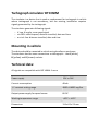
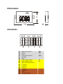
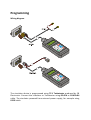
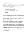
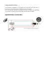
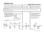
Tachograph simulator
DTCOSIM
SERVICE MANUAL
Ver. 1.0 05.2013 © KT
Tachograph simulator DTCOSIM
The simulator is a device that is used as replacement for tachograph in vehicle
where tachograph is not mandatory, but the existing installation requires
signals generated by the tachograph.
The simulator generates following signals:
− V imp, 4 imp/m, zero speed signal
− via CAN: vehicle speed, distance travelled, date and time
− or via k-line: distance travelled, date and time
Mounting in vehicle
The device should be mounted in vehicle using handles on enclosure.
The simulator has the same connections as tachograph – the A [white],
B [yellow] and D [brown] sockets.
Technical data:
All signals are compatible with ISO 16844-1 norm
Power supply
12V or 24V
Current consumption
40mA
„k” constant setting range
4000 ÷ 64000 imp/km
Output power supply for speed sensor
8V DC
Working temperature range
–40°C ÷ +85°C
Dimensions
113 x 65 x 23 mm
Dimensions
Connector
A1
A3
A4
A5
A7
A8
B1
B2
B3
B6
B7
B8
D3
D6
D7
D8
Power from battery
Ignition
CAN H
Ground from battery
CAN GND
CAN L
Power supply output
Power supply output
Signal from speed sensor
V-impulse
V-impulse
4 imp/m
V-impulse
V-impulse
K-line
Zero speed signal
[30]
[15]
[31a]
[+]
[-]
Programming
Wiring diagram
The simulator device is programmed using TC-1 Tachotester produced by CB
Electronics. Connect the simulator to Tachotester using 02.45A or 02.45A.04
cable. The simulator powered from external power supply, for example using
02.09 cable
Programming simulator
Choose the „SiemensVDO 1324” in Tachotester main menu and press “START”.
The Tachotester will read simulator settings. Some of these parameter must be
changed to allow proper work of simulator
Following parameters of DTCOSIM simulator can be changed:
• Odo – odometer
• w – characteristic constant of vehicle
• PTO - number of impulses per one shaft revolution
• ES - product code
• VIN - vehicle identification number
• System time
Programming product code
The product code should be read from the tachograph that will be replaced by
tachograph simulator, and entered into simulator settings.
The simulator device need valid product code to function properly.
Second digit after dot - determines type of CAN bus. Allowed digits are: 0, 2, 3
and 4 (for ex. 1324.x2xxxxxxxxxx).
If second digit after dot is “1” that means the tachograph has built-in
terminating resistor 120ohm between A4 and A8 pin. The CAN bus requires
such resistor in one of devices connected to bus, to work properly. If the
tachograph with terminating resistor is replaced by the simulator (which
doesn’t have terminating resistor), the resistor must be added.
This can be done by soldering 120 ohm 0.25W resistor to lines A4 and A8, for
example inside the white connector. After adding the terminating resistor, the
second digit after dot in code can be changed to “2” (1324. x2xxxxxxxxxx)
Third digit after dot – determines the interface is k-line. Setting this digit to 1
will turn on the k-line. In the same time the second digit after dot should be set
to 0 to turn off the CAN interface. Additionally the 12-th digit should be set the
same as 3-rd digit. Example product code for k-line interfaced simulator is:
1324.601000000001.
Programming date and time
The simulator is equipped in very precise real time clock (error less than ± 2
minutes per year) with automatic daylight saving time switch.
The clock must be initialized by setting correct date, UCT/GMT time and offset.
The simulator is factory set to correct date and time with +1h offset.
Speedometer connection
Rcan
120 ohm*
* the value depends on CAN bus line resistance