1
Tachometer Installation and Operation Instructions
Addendum for Dual Shift Point (DSP) Eliminator Tachometer
Siemens VDO
Allentown, Pennsylvania USA
THE INSTRUCTIONS FOR OPERATION AND ELECTRICAL WIRING FOR THIS TACHOMETER FOLLOWS. USE IS RESTRICTED TO 12 VOLT NEGATIVE GROUND ELECTRICAL SYSTEMS.
IMPORTANT: The installation and general wiring
for this tachometer is essentially the same as for those
mentioned elsewhere in these instructions. There are
minor differences, however, which are described
here. Please read and understand them before
proceeding.
I. DSP Tach Switch Settings and Wiring
Wiring for the Top DSP Eliminator and Pro DSP Eliminator
is the same as for the other tachometers. Please refer to the
proper sections in the main Eliminator Tachometer Installation
and Operation Instructions to determine the proper switch settings and wiring for the vehicle and tachometer you are using.
Also, refer to the diagrams contained in this addendum and
note the subtle changes between the DSP Eliminator Tachometers and the other Eliminator Tachometers.
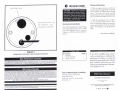
a dot will appear in the upper right hand corner
of the display, to indicate that you are in the
set shift point mode. On the display itself, S1 will appear for one second, then the LED will
display the current 1st shift value. Press the up
(▲) or down (▼) arrow until the display reads
your desired RPM value. When it does, press
the TACH / RPM SET button again. Your first
shift point is now set.
RECALL
▲
TACH
START
▼
Now the display will show S-2 for one second, followed by the
current 2nd shift RPM value. If you wish to change the second shift point to a new RPM value, simply repeat the previous instructions for setting the desired value. When you have
done so, press the TACH / RPM SET button to return to the
TACH mode.
TO START RECORDING:
Top DSP Eliminator:
II. DSP Eliminator Tachometer Operation
The unique feature of these tachometers is the capability to
have two (2) shift light indications. Note, however, that the
RPM value of the second shift point must be higher than the
RPM value of the first shift point.
Setting the Shift Points:
1. To set the shift points, press the TACH/RPM SET button.
The tach pointer will move to approximately 3000 RPM, and
Press the START button to begin recording. When you do,
the display will indicate .0.0.1 until the first shift point is
reached. Then, the display will show .0.0.2 to indicate a
change from the first shift point to the second shift point. The
display will continue to show the second shift point until it is
reset by any of the following methods:
1.
2.
3.
4.
Toggling power
Resetting the shift points
Starting the memory
Recalling memory.
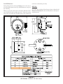
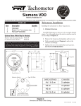
*5((1
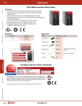
,JQLWLRQ 7DFKRPHWHU VLJQDO FRQQHFWLRQ
:+,7(
,OOXPLQDWLRQ VZLWFKHG Y IURP OLJKW VZLWFK
%/$&.
7DFK JURXQG FRQQHFW WR FRPPRQ FKDVVLV JURXQG
5('
YROW SRZHU FRQQHFW WR IXVH SDQHO
<(//2:
2SWLRQDO H[WHULRU VKLIW OLJKW
Diagram A
DSP Eliminator Wire Color Code and Hookup Description
Part # 0 511 012 428 Rev. 07/03
Pro DSP Eliminator:
until reset as described previously.
Setting shift points for the Pro DSP Eliminator is the same as
for setting shift points for the Top DSP Eliminator, except for
the following:
RECALL:
When you press the clear button, the display will flash 0.00
twice, followed by the 1st shift point value. After the 1st shift
point value is reached, the 2nd shift point value is displayed
To recall your recording, follow the procedures outlined for all
Eliminator Tachometers in the main Installation and Operating Instructions.
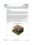
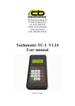
Diagram B
DSP Eliminator Dimensions and Switch Settings
ON
Siemens VDO
http://sso-usa.siemensvdo.com/ Phone: 1-800-265-1818
Performance Shift Light Tachometer
Performance Tachometer
Installation and Operation Instructions
Siemens VDO
Allentown, Pennsylvania USA
THE INSTRUCTIONS FOR INSTALLATION AND ELECTRICAL WIRING FOR THESE TACHOMETERS FOLLOW. USE IS RESTRICTED TO 12 VOLT NEGATIVE GROUND ELECTRICAL SYSTEMS.
Tachometer Installation
Parts List
Item
Description
1.
2.
3.
4.
1. Cylinder Selection
Quantity
Tachometer
Decals, 2 x 4 (not contingency decals)
Green Lamp Cover
Red Lamp Cover
1
2
2
2
Your tachometer is factory programmed for an eight cylinder engine. For other applications the selector switches must
be set according to Diagram A.
CAUTION: Read these instructions thoroughly before making installation. Always wear safety glasses, and always disconnect the battery ground before making any electrical connections. If in doubt,
please contact your dealer or VDO Instruments at 1-800-265-1818.
PP
Remove the 3 Philips head screws from the rear cover.
·
Remove the rear cover.
·
Find your application in Diagram A and set the
switches accordingly.
·
Replace the rear cover and three screws.
DO NOT OVERTIGHTEN!
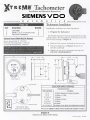
3 21
OFF
ON
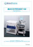
6HOHFWRU
6ZLWFKHV
6KLIW
/LJKW
&RQWURO.QRE
6KLIW
/LJKW
·
/DPS
$VVHPEOLHV
3 21
OFF
ON
7DFKRPHWHU%DFN
UHDUFRYHUUHPRYHG
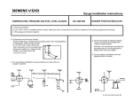
6(/(&7256:,7&+6(77,1*6
&</,1'(56
6:,7&+6(77,1*6
RQ
RQ
RQ
RQ
PP
PP
%/8(
5('
*5((1
%/$&.
:+,7(
,OOXPLQDWLRQJURXQGFRQQHFWWRFRPPRQFKDVVLVJURXQG
YROWSRZHUFRQQHFWWRIXVHSDQHO
,JQLWLRQ7DFKRPHWHUVLJQDOFRQQHFWLRQ
7DFKJURXQGFRQQHFWWRFRPPRQFKDVVLVJURXQG
YROWLOOXPLQDWLRQFRQQHFWWROLJKWVZLWFK
Diagram A
Dimensions, Selector Switch Settings and Wiring Chart
P/N 0 515 010 516
Rev. 07/03
2. Colored Illumination
IGNITION
You may use the colored lamp covers to customize your
tachometers illumination.
·
·
·
·
·
·
·
·
Remove the 3 Phillips head screws from the rear cover.
Remove the rear cover.
Using long nose pliers, gently grip one of the lamp
assemblies and give it about a quarter-turn counterclockwise.
Lift the lamp assembly straight out.
Slide the colored lamp cover of your choice over the
bulb section of the lamp assembly.
Reinsert the lamp assembly, and lock it into position
with about a quarter-turn clockwise.
Repeat this procedure for the second lamp assembly.
Replace the rear cover and the three screws.
DO NOT OVERTIGHTEN!
3. Mounting the Tachometer
Determine the mounting position for your Tachometer that
is best for you. The mounting bracket may be bent to adjust
the viewing angle of your Tachometers face.
·
·
Recommended installation is on the steering column
using a band clamp (available at a local auto parts
store).
Dash mounting uses the two holes provided in the base
of the mounting bracket to secure the tachometer to
the dash.
4. Wiring the Tachometer
TYPE
CONNECTIONS
Standard
points / breakerless
negative terminal on
coil
CD
points
points connection to
CD box
breakerless
positive terminal on
coil
MSD, ACCEL,
MALLORY, DDIS
(distributorless),
etc.
Tach output terminal
on ignition box, or
points connection to
ignition box, or
negative coil
Electronic
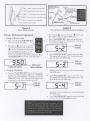
5. Shift Light Operation
(Performance Shift Light Tachometers Only)
The RED Shift Light on your Tachometers face (refer to
Diagram A) will light up whenever your engine is running at
or above your pre-set Shift Point RPM.
1. Setting the Shift Point:
·
·
·
Turn ON the ignition. The engine MAY be running.
Push in the Shift Light Control Knob (Diagram A).
The RED Shift Light will turn on and the tachometer
pointer will show the current Shift Point RPM.
· While holding in the Control Knob, slowly turn it until
the tachometer pointer indicates your desired Shift
Point RPM.
· Release the Control Knob. The Shift Light will turn
OFF and your Shift Point RPM is set.
2. Checking the Shift Point:
·
Turn off the ignition and disconnect the negative
terminal from the battery post if you havent already
done so.
·
Wire the tachometer to the vehicle as shown in
Diagram A.
·
Turn ON the ignition. The engine MAY be running.
·
Push in the Shift Light Control Knob.
** Refer to your vehicles owner/service manual or the
aftermarket ignition manufacturers instructions for
the recommended place to tap the signal. Typical
examples are shown in the table at upper right.
·
The RED Shift Light will turn on and the tachometer
pointer will show the current Shift Point RPM.
·
You can quickly check your Shift Point RPM at any time,
even while the engine is RUNNING:
Reconnect the battery and start your vehicle to test.
Siemens VDO Limited Warranty
VDO North America, LLC. warrants all merchandise against defects in factory workmanship and materials for a period of 24 months after purchase. This warranty
applies to the first retail purchaser and covers only those products exposed to
normal use or service. Provisions of this warranty shall not apply to a VDO product
used for a purpose for which it is not designed, or which has been altered in any
way that would be detrimental to the performance or life of the product, or misapplication, misuse, negligence or accident. On any part or product found to be
defective after examination by VDO North America, VDO North America will only
repair or replace the merchandise through the original selling dealer or on a direct
basis. VDO North America assumes no responsibility for diagnosis, removal and/
or installation labor, loss of vehicle use, loss of time, inconvenience or any other
consequential expenses. The warranties herin are in lieu of any other expressed or
implied warranties, including any implied warranty of merchantability or fitness,
and any other obligation on the part of VDO North America, or selling dealer.
(NOTE: This is a Limited Warranty as defined by the Magnuson-Moss Warranty Act of 1975.)
Siemens VDO Instruments . http://sso-usa.siemensvdo.com/ . Phone: 1-800-265-1818