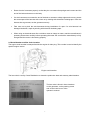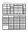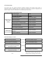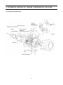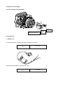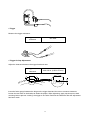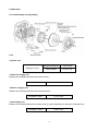
1
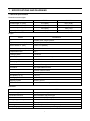
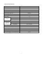
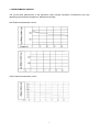
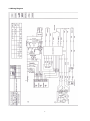
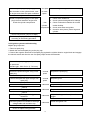
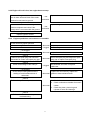
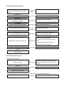
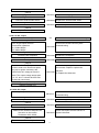
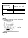
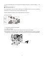
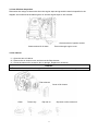
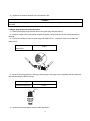
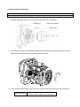
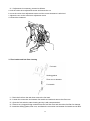
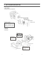
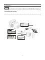
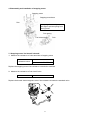
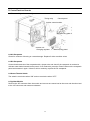
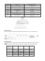
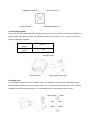
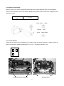
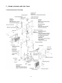
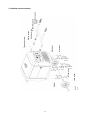
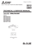
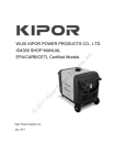
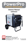
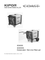
IG6000 IG6000h Generator Service Manual The Coast Distribution System, June 1, 2007 Preface This manual covers the construction, function and servicing procedure of the Coast Distribution System KIPOR IG6000 model generator. This manual is principally concerned with the generator specifications, function, troubleshooting and repair. There is a separate manual to cover engine overhaul which includes the starting systems. These models may be of significantly different design than the original KGE7000Ti and other models currently sold outside North America. Contact Kipor for current service information. Careful observance of the instructions contained in this manual will result in safe and quality service work. All information, illustrations, directions and specifications included in this publication are based on the latest product information available at the time of approval for printing. KIPOR POWER CO., LTD, reserves the right to make changes without incurring any obligation whatever. No part of this publication may be reproduced without written permission. TABLE OF CONTENTS 1. Specifications.........................................................................................................................................1 1.1 General Specifications..................................................................................................................1 1.2 Generator Specifications2..............................................................................................................2 1.3 Performance Curves......................................................................................................................3 1.4 Wiring Diagram..............................................................................................................................4 2. Service and Maintenance ……………………………………………………………………………………. 5 2.1 The Importance of Proper Service.……………………………………………………………………...5 2.2 Safety Precautions.…………………………………………………………………………………….....5 2.3 Service Rules.................................................................................................................................6 2.4 Electrical Precautions......……………………………………………………………………………......7 2.5 Serial Number and Bar Code Location..........................................................................................7 2.6 Alternator Service Standards.…………………………………………………………………………....8 2.7 Fastening Torques.………………………………………………………………………………………..8 2.8 Troubleshooting.…………………………………………………………………………………………..9 2.8.1 General Symptoms and Repair ……………………………………………………………….....9 2.8.2 Hard Starting or No Start .....................................................................................................9 2.8.3 Ignition System …………………………………………………………………………………..10 2.8.4 Low Oil Level Alarm .……………………………………………………………………………..11 2.8.5 Engine Speed Problems .………………………………………………………………………..11 2.8.6 Engine Stops After Starting.……………………………………………………………………..12 2.8.7 Throttle Control System......................................................................................................12 2.8.8 Low AC Output. …………………………………………………………………………………..13 2.8.9 No AC Output.…………………………………………………………………………………….13 2.8.10 Electric Starter. ………………………………………………………………………………....14 2.8.11 Battery Charging...............................................................................................................14 3. Inspection and Adjustment...................................................................................................................15 3.1 Maintenance Schedule.................................................................................................................15 3.2 Engine Oil.....................................................................................................................................15 3.3 Low Oil Level Switch .................................................................................................................17 3.4 Air Cleaner....................................................................................................................................17 3.5 Spark Plug....................................................................................................................................18 3.6 Valve Clearance. ......................................................................................................................... 19 3.7 Fuel Switch/Fuel Filter................................................................................................................. 20 4. Air Cleaner/Muffler...............................................................................................................................21 4.1 Air Cleaner....................................................................................................................................21 4.2 Muffler...........................................................................................................................................21 5. Carburetor ...........................................................................................................................................22 5.1 Disassembly and Reassembly......................................................................................................22 5.2 Stepping Motor/Fuel Shutoff Solenoid..........................................................................................23 6. Control Panel and Inverter Module......................................................................................................24 6.1 Disassembly and Reassembly.....................................................................................................24 6.2 AC Receptacles............................................................................................................................24 6.3 DC Receptacle.............................................................................................................................24 6.4 Smart Throttle Switch...................................................................................................................24 6.5 Ignition Module.............................................................................................................................24 6.6 Ignition Switch..............................................................................................................................25 6.7 Bridge Rectifier.............................................................................................................................25 6.8 Charge Regulator.........................................................................................................................26 6.9 Timing Relay.................................................................................................................................26 6.10 Ignition Control Module...............................................................................................................27 6.11 Inverter Module...........................................................................................................................27 7. Frame, Housing, and Fuel Tank...........................................................................................................28 7.1 Disassembly and Reassembly......................................................................................................28 7.2 IG600h Handle Assembly.............................................................................................................29 8. Ignition Coil, Trigger, Alternator............................................................................................................30 8.1 Component Identification..............................................................................................................30 8.2 Ignition Coil and Trigger................................................................................................................31 8.2.1 Disassembly and Reassembly...........................................................................................31 8.2.2 Inspection...........................................................................................................................31 8.3 Alternator......................................................................................................................................33 8.3.1 Disassembly and Reassembly...........................................................................................33 8.3.2 Inspection...........................................................................................................................33 1.SPECIFICATIONS AND DIAGRAMS 1.1 General Specifications Dimensions and weights Model IG6000 IG6000H Overall length- in. (mm) 31.6 (802) 48.6 (1235) Overall width- in. (mm) 19.5 (498) 25.6 (650) Overall height- in. (mm) 24.6 (624) 30.3 (770) 209 (95) 223 (103) Dry weight- lbs. (Kg) Engine Model KG390GETi Type 4-stroke,OHV, single cylinder Displacement- cu.in. (cc) 23.7 (389) Bore x stroke- in. (mm) 3.46 x 2.51 (88×64) Maximum horsepower(KVA) 7.7/3600 Compression ratio 8.5:1 Cooling system Forced air Ignition system Transistorized controlled ignition Ignition timing 28°B.T.D.C Spark plug F7RTC Carburetor Horizontal float type Air cleaner Dry replaceable element Governor Inverter module control Lubrication system Forced splash Oil capacity- qt. (L) 1.2 (1.1) Starting system Electric starter Stopping system Electric ground Fuel Automotive unleaded gasoline 87 octane Generator Model KD50 Generator type Multi pole rotation type Generator structure Self-ventilation drip-proof type Excitation Self-excitation (Magnet type) Voltage regulation system Pulse Width Modulation Phase Three phase Rotating direction Clockwise (Viewed from the generator) Frequency regulation AC-DC-AC conversion (Inverter type) 1 1.2 Generator Specifications Model IG6000 Maximum output(AC) 6.0 KVA Rated output (AC) 5.5 KVA Rated frequency (HZ) 60 Rated voltage(AC) 120/240 Maximum current (amp) 25/50 Rated current(amp)★ 23.9/45.8 Rated voltage(DC) 12V Rated current(DC) 12A Power factor 1.0 Voltage variation rate Momentary Max.10% Average Max.1.5% Average time Max. 3 seconds Voltage stability Frequency variation rate ±1% Momentary Max. .5% Average Max. .5% Average time Max. .05 second Frequency stability ±0.1% Min. 10MΩ Insulation resistance AC circuit protector- Amps 120/240 VAC 51.7/25.8 DC circuit protector 15A Fuel tank capacity- gal (L) 5.9 (22) Operating hours at rated load 6 Noise level dB @23’ (7 m) no load-full load 63~70 2 1.3 PERFORMANCE CURVES The curves show performance of the generator under average conditions. Performance may vary depending upon ambient temperature, altitude and humidity. ●AC External characteristic curves ● DC External characteristic curves 3 1.4 Wiring Diagram 4 2. SERVICE AND MAINTENANCE 2.1 The importance of proper servicing Proper servicing is essential to the safety of the operator and the reliability of the generator. Any error or oversight made by the technician while servicing can easily result in faulty operation and/or damage to the equipment or injury to the operator. ! Warning Improper servicing can cause an unsafe condition that can lead to serious injury or death. Follow the procedures and precautions in this shop manual carefully. Some of the most important precautions are stated below. 2.2 Safety Precautions Be sure you have a clear understanding of all basic shop safety practices and that you are wearing appropriate clothing and safety equipment. When performing maintenance or repairs, be especially careful of the following: Read the instructions before you begin, and be sure you have the tools and skills required to perform the tasks safely. Be sure that the engine is off before you begin any maintenance or repairs. This will reduce the possibility of several hazards: - Carbon monoxide poisoning from engine exhaust. - Burns from hot parts. - Injury from moving parts. Do not run the engine unless the instructions tell you to do so. Keep your hands and clothing away from rotating parts. To reduce the possibility of fire or explosion, exercise extreme caution when working around gasoline. Use only a nonflammable solvent, not gasoline, to clean parts. Keep cigarettes, sparks and flames away from all fuel-related parts. 5 2.3 Service Rules Use genuine KIPOR or KIPOR recommended parts and lubricants or their equivalents. Parts that do not meet Kipor’s design specifications may damage the engine and void the warranty. Use special tools designed for the product when specified. Always install new gaskets, O-rings, etc. when reassembling components. Clean parts in cleaning solvent upon disassembly. Lubricate any sliding surfaces before reassembly. After reassembly, check all parts for proper installation and operation. Many screws used in this machine are self-tapping. Be aware that cross-threading or over tightening these screws will strip the threads and ruin the hole. Use only metric tools when servicing this engine. Metric bolts, nuts and screws are not interchangeable with non-metric fasteners. The use of incorrect tools and fasteners will damage the engine. 2.4 Electrical Precautions Hold the connector body to disconnect the connector. Do not disconnect by pulling the wire harness. To disconnect the locking connector, be sure to unlock first, and then disconnect. Check the connector terminals for bend, excessive extrusion, missing terminals, or other abnormalities before connecting the connector. To connect, insert the connector as far as it goes. If the connector is a locking type, be sure that it is locked securely. Check the connector cover for breakage and check whether the connector female terminal is not opened excessively. Then, connect the connector securely. Check the connector terminal for rust. Remove the rust using an emery paper or equivalent material before connecting the connector. Set the harness clips in the specified places of the frame securely, and secure the wire harnesses. Clamp the cables securely. Clamp the wire harnesses securely so that they do not interfere with the rotating parts, moving parts and hot parts. Route and connect the wire harnesses properly. Be sure that the harnesses are not slack, twisted or pulled overly taut. 6 Route the wire harnesses properly so that they do not contact sharp edges and corners and the end of the bolts and screws on the body. If a wire harness must contact the end of the bolts or screws or sharp edges and corners, protect the contact part of the harness with a loom or by winding with electrical insulating tape. If the wire harness has a grommet, set the grommet securely. Take care not to pinch the wire harnesses during installation of a part. If a wire harness has damaged insulation, repair by winding with electrical insulating tape. When using an electrical tester like a volt/ohm meter or clamp on meter, read the manufacturer’s operating instructions carefully before operating the tester. Be sure that the tester battery is fully charged and the meter is functioning properly 2.5 Serial Number and Bar Code Location The engine serial number is stamped beside the engine oil drain plug. This number is used to identify the specific engine version. Engine serial number The bar code is used by Coast Distribution to determine production date and warranty administration. The bar code is found in three locations: on the generator, on the packing carton and on the inside cover of the operator’s manual. 7 2.6 Alternator Maintenance Standards Part Item Standard(Ω) Type Service limit 120V/240V Ignition winding l External charging winding Built-in charging winding Resistance Resistance Orange- Yellow/Green 0.22~0.24 Gray-orange 0.15~0.17 Blue-blue 0.03~0.04 Resistance Purple-Purple 0.12~0.16 0.08~0.12 Sub winding Resistance White-white (green-green) Main winding Resistance Black-black (red-red) 0.45~0.60 0.09~0.10 0. 9~1.1 2.7 Fastening Torques Tightening torque Item Specification Ft lb. N.m Connecting rod bolt M8 14.8~16.3 20~22 Cylinder cover bolt M10×1.25×80 31.0~34.0 42~46 Spark plug M14×1.25×19 18.4~22.2 25~30 Crankcase side cover bolt M8×30 14.8~17.0 20~23 Rotor nut M18×1.5 88.5~95.9 120~130 Rocker arm shaft bolt M8×16 14.8~17.0 20~23 Adjusting nut of rocker arm shaft M6×0.75 7.8~8.8 10~12 M5 bolt、nut 4.4~5.9 6~8 M6 bolt、nut 5.9~7.4 8~10 M8 bolt、nut 14.8~17.0 20~23 M10 bolt、nut 40.6~44.3 55~60 Standard torque Note: Use standard torque values for fasteners that are not listed in this table. 8 2.8 Troubleshooting This section gives very general information regarding symptoms and possible causes. Refer to subsequent sections regarding testing and removal and replacement of specific components and systems. Engine overhaul is addressed in the IG6000 Engine shop manual. 2.8.1 General symptoms and possible causes Engine does not start or hard starting Engine speed does not stabilize Fuel filter clogged Clean Fuel hose clogged Clean Fuel switch won’t operate Replace Carburetor defective Clean and/or replace Ignition coil defective Spark plug defective Inspect and replace Defective timing relay Inspect and replace Trigger defective or improper air gap Inspect and replace Spark plug cap disconnected Install securely Oil level alarm defective Inspect and replace Ignition coil defective Inspect and replace Valve clearance misadjusted Adjust valves Carburetor faulty Clean and/or replace Throttle control motor (stepping motor) Inspect and replace Inspect and replace defective Inverter unit defective Inspect and replace Valve clearance misadjusted Adjust valves 2.8.2 Hard starting or no start Check the fuel level in the tank ↓Sufficient fuel Check fuel switch is in ON position →no fuel Add fuel and restart the engine →off Turn on it and restart the engine ↓on Loosen the drain screw and check whether fuel reaches bowl and whether Check fuel system for blockage →abnormal the fuel level is normal ↓normal Remove and check spark plug and check if electrode is wet or dry →dry Check carburetor for fuel delivery Clean and dry the carburetor and observe ↓wet → 9 choke action. is severe, check if any fuel leakage and if the floating valve is normal Attach the spark plug on plug cap, ground →no spark the electrode on the cylinder head.; start or weak the engine and check the spark conditions spark Perform the ignition system troubleshooting ↓normal Install a compression gauge in the spark 1. Check valve clearance; plug hole and restart the engine and 2. check cylinder head gasket for leakage →low check the cylinder compression cylinder 3. Check combustion chamber for excess carbon buildup compression 4. check valve seats and guides 5. check for worn piston, piston rings and cylinder ↓normal compression (80 psi/.55 Mpa) Install the spark plug. Restart the engine according to the starting procedure. 2.8.3 Ignition system troubleshooting ■Spark plug inspection 1. Remove spark plug 2. Attach the removed spark plug to the plug cap 3. Ground the negative electrode of the spark plug against the cylinder head or engine block and engage the electric starter and check to see if a spark jumps across the electrode. Measure the spark plug gap and perform the spark test. Standard gap: .028-.034 in. (0.7-0.8 mm) ↓no spark Perform the spark test again using a new spark plug →normal Replace the spark plug spark ↓no spark Perform the spark test again using a new →normal spark plug spark Replace Ignitor ↓no spark Check ignition module →abnormal Replace the ignition module →abnormal Replace the coil ↓normal Check resistance of ignition coil ↓normal Check trigger air gap and trigger resistance →abnormal Adjust the air gap and/or replace the trigger ↓normal Check the ignition coil resistance and high voltage cable and insulation cap →abnormal ↓ Check or replace wiring harness 10 Check the ignition coil 2.8.4 Engine oil level is low, but engine does not stop. Drain out all engine oil, disconnect the low oil alarm wire and check if the outlet terminal is connected to ground →not Replace the oil level alarm switch conductive ↓conductive Connect the alarm wire, loosen ignition module receptacle and check if the orange wire is connected with the ground →not Repair wiring harness conductive ↓conductive Replace ignition module 2.8.5 Engine speed does not increase or is unstable Check choke for proper operation ↓ OK Check the air cleaner →abnormal →clogged Adjust/repair choke mechanism Clean or replace air cleaner ↓not clogged Check the valve clearance →abnormal Adjust the valve clearance ↓normal Remove the spark plug and check the electrodes for carbon and spark plug gap →abnormal Clean the spark plug and adjust the spark plug gap or replace new spark plug ↓normal Check for blockage of the main jet →clogged Disassemble and clean or replace carburetor ↓not clogged Check the air intake gasket and the sealing of heat-insulation block of Tighten the nuts securely, replace the →abnormal gasket or heat-insulation block carburetor ↓normal Perform the cylinder compression check 1. Check the valve clearance 2. Check combustion chamber for excess →abnormal carbon 3. Check the piston, piston ring and cylinder for wear and damage. ↓normal Perform the throttle control system troubleshooting 11 2.8.6 Engine stops after starting Check the engine oil level and check if oil level alarm activates when rotation stops →oil level Add oil and restart the engine alarm ↓sufficient oil Check the fuel in fuel tank →no fuel Add fuel and restart the engine ↓sufficient fuel Check for operation of fuel switch and blockage in fuel filter →clogged Clean the fuel switch and filter ↓not clogged Check for blockage of fuel hoses →clogged Clean or replace the hoses ↓not clogged Check for carburetor fuel delivery →not Disassemble and clean fueling ↓normal fuel flow Check the intake gasket and the sealing of carburetor heat-insulation block →abnormal Tighten the nuts securely, replace the gasket or heat-insulation block ↓normal 1. Check the valve clearance 2. Check if too much carbon in burning Measure the cylinder compression →abnormal room 3. Check the piston, piston ring and cylinder for wear and damage. ↓normal Check the trigger air gap →abnormal Readjust the clearance ↓normal Perform throttle control system troubleshooting 2.8.7 Throttle control system a. Engine speed is too high Perform the generator troubleshooting Check AC output abnormal flowing the instruction of “No or Low AC output” ↓normal Check the stepping motor →abnormal Replace the stepping motor ↓normal Replace the inverter unit b. The engine speed does not increase when smart throttle is on and load is increased. Perform the generator troubleshooting Check the AC output →abnormal flowing the instruction of “No or Low AC 12 output” ↓normal Check the stepping motor →abnormal Replace the stepping motor →abnormal Replace the smart throttle switch →abnormal Repair or replace the wire harness ↓normal Check the smart throttle switch ↓normal Check “Smart” switch wire ↓normal Replace the inverter unit 2.8.8 Low AC output Is the overload indicator light ON? ↓off Is the engine speed normal? Smart switch operation: On: 2500±100rpm Off: 3600±100rpm →on Disconnect the load, and restart the engine. Perform the throttle control system →abnormal troubleshooting →abnormal Replace the receptacle →abnormal Replace the connector ↓normal Check the AC receptacle ↓normal Check the AC output connector ↓normal Disconnect the two 4P input connectors on the inverter unit. Disconnect spark plug cap or igniter connector, and measure the AC voltage of from the stator. The output voltage across pins 1-2, 2-3, and 1-3 should be 255 volts. Check both connectors. ↓normal (255 volts) 1. Check the wiring of the stator leads in the harness. Repair or replace the harness. →abnormal 2. Replace the alternator. Replace inverter unit 2.8.9 No AC output Is the engine speed normal? abnormal Perform the throttle control system troubleshooting ↓normal Check AC receptacles →abnormal Repair wiring or replace receptacles2.7.9 →abnormal Replace the rectifier ↓normal Check the rectifier ↓normal Measure the resistance between two blue wire on the rectifier Check and repair the wire harness or →abnormal Resistance:0.03~0.04Ω ↓normal Rotor losses excitation, replace the rotor 13 replace the stator 2.8.10 Electric Starter Check the battery voltage →abnormal Charge or replace the battery →abnormal Replace the ignition switch →abnormal Replace ignition relay →abnormal Replace the starting motor ↓normal Check ignition switch ↓normal Check the ignition relay ↓normal Check the starting motor ↓normal Check and repair or replace main wire harness 2.8.11 The battery will not charge or maintain a charge Check ignition switch →abnormal Replace ignition switch →abnormal Replace the charging regulator ↓normal Check charging regulator ↓normal Measure resistance of charging coil winding Check and repair electric wire harness or →abnormal Resistance: 0.12~0.16Ω: ↓ Check and repair or replace wire harness 14 replace stator. 3. INSPECTION AND ADJUSTMENT 3.1 MAINTENANCE SCHEDULE Regular service period(1) Item perform at every indicated month or operating hour interval, whichever comes first Each use Project Engine Oil Each month or every 10 hours Every 6 months or every 100 hours Every year or every 300 hours ● Check ● Replace Air cleaner Every 3 months or every 50 hours ● ● Check ●* Replace Spark plug Clean-Adjust ● Spark Arrestor Clean ● Valve clearance Check-Adjust ●** Fuel tank and filter Clean ●** Fuel line Check Every 2 years and replace if necessary Note: * Service more often in dirty dusty conditions ** Should be performed by trained service center personnel 3.2 Engine oil ● Checking the oil level Stop the engine and check the oil level, be sure to put the engine on a flat floor when checking. (1)Remove the oil dipstick and check the level. Lower limit Upper limit (2)If the oil level is low, add to the edge of the oil filler port (upper limit). ● Engine oil change (1)Remove dipstick and oil drain bolt and drain out the used oil. (2)Tighten the oil drain bolt securely. 15 (3)Pour the specified amount of fresh engine oil through the oil filler port.(Engine oil capacity : 1.2 qt (1.1L) ※ Recommended engine oil: Use a high-detergent, premium quality 4-stroke engine oil, certified to meet or exceed U.S. automobile manufacturer’s requirements for API Service Classification SG, SF. Select the appropriate viscosity for the average temperature in your area. SAE Viscosity Grades (4)After refilling, check the oil level again.. (5)Tighten the dipstick. ● drain the used oil while the engine is warm. Warm oil drains quickly and completely. ● please dispose of the used motor oil in a manner that is compatible with the environment. We suggest you take used oil in a sealed container to your local recycling center or service station for reclamation. 16 3.3 Low Oil alarm inspection Disconnect the orange oil alarm wire when the engine stops and ground the terminal specified in the diagram and confirm that the alarm light is on and the engine stops or won’t restart. Outlet terminal of ignition module Ground through engine cover Outlet terminal of oil alarm 3.4 Air Cleaner (1)Open the door of cabinet. (2)Remove the air cleaner cover and remove the filter element. (3)Check the element for excessive dirt or damage. Replace as necessary Caution: ●Excess oil will restrict air flow through the foam filter core and may smoke at the engine start. Filter element Cover of ail cleaner Clean Twist to dry Dip into oil 17 Squeeze out the excess oil (4)Install the air cleaner element in the air cleaner case. Caution Do not operation the engine without an air filter element or with a damaged air filter. Rapid engine wear will result 3.5 Spark plug inspection and adjustment: (1)Remove the spark plug cap and remove the spark plug with plug sleeve (2)Remove carbon on the electrodes of spark plug with a wiey brush and check sealing washer for damage. (3)Check the resistance value of spark plug and replace if the resistance value is not within the stated value. Resistance value of spark plug 3~9KΩ (4)Measure the plug gap with a wire-type feeler gauge. If the gap is not compatible with the standard, adjust by bending the side electrode. Spark plug gap .028-.034 in. (0.7~0.8 mm) Standard spark plug F7RTC 0.7-0.8 (5)Install the plug and tighten securely after adjustment. 18 3.6 Valve clearance adjustment Caution ● Valve clearance inspection and adjustment must be performed on a cold engine. (1)Remove spark plug, valve cover bolt, valve cover and valve cover gasket. Spark plug Valve cover gasket Valve cover (2)Insert a feeler gauge in the spark plug installation hole; Rotate the engine so the piston is at top dead center and both intake and exhaust valves are closed. r (3)Insert a feeler gauge between the rocker arm and the valve and measure the valve clearance. Valve clearance intake:.0039 ± .0001 in. (0.10 ± 0.02 mm) exhaust:.0059 ± .0001 (0.15 ± 0.02 mm) 19 (4)If adjustment is necessary, proceed as follows: a. lock the rocker lever adjustment screw and loosen the nut. b. move the rocker lever adjustment screw until the correct clearance is acheived. c. tighten the nut on the rocker arm adjustment screw. d. recheck the clearance. 3.7 Fuel switch and fuel filter cleaning Fuel tank Sealing gasket Filter core or element Fuel switch (1)Drain the fuel from the tank then remove the fuel tank. (2)Loosen the connection nut between fuel switch and tank and remove the filter core. (3)Open the fuel switch to start cleaning and dry it with compressed air. (4)Remove any clogged foreign material from the fuel filter core and check the fuel filter for damage. (5)Install the sealing gasket, filter core, and fasten the connection nut between fuel switch and oil tank. 20 4.AIR CLEANER AND MUFFLER 4.1 Air cleaner ● Disassemble and reassemble Bottom case of air filter Sealed gasket Filter fixed price Filter element Air filter cover Carburetor gasket Install: Make sure that gaskets have no damage or deformation. Check sealing surfaces on all four sides 4.2 Muffler ● Assembly Muffler syphon Fireproofing cap Assembly: Clean the carbon using the brush before installing Exhaust pipe gasket Muffler gasket Muffler Assembly: Knock it to remove carbon inside by using rubber hammer before installing. Cover of muffler 21 5.Carburetor WARNING This carburetor is not to be rebuilt nor adjusted and no repair parts will be furnished. The only maintenance permitted other than cleaning is to replace the main jet for high altitude compensation. 5.1 Disassembly and reassembly NOTE: loosen the drain bolt at the bottom of the bowl and drain fuel from the carburetor before removal. Carburetor gasket A 28 Reassembly: Check if there is any damage in the gasket before assembly 22 ● Disassembly and installation of stepping motor Stepping motor Stepping motor base Fork Fork spring disassembly: Hold tight to prevent spring from coming loose . Fork spring Fuel control lever Fork 5.2 Stepping motor/ fuel shutoff solenoid 1)Measure the resistance of outlet terminals of stepping motor resistance value 1 and 3:50~55Ω 2 and 4:50~55Ω Replace the stepping motor if the resistance exceeds the standard. 2)Measure the resistance of fuel shutoff valve resistance value 6~8Ω Replace the throttle electromagnetic valve if the resistance exceeds the standard value 23 1 2 4 3 6. Control Panel and Inverter 6.1 Disassembly and reassembly Timing relay Control panel Ignition control module Module fixing plate 2 Inverter unit Charging regulator Module fixing plate1 6.2 AC Receptacle Check for evidence of burning or contact damage. Replace if either condition exists. 6.3 DC Receptacle Connect both terminals of the receptacle with a jumper wire and check if the receptacle is conductive with two meter leads inserted into the panel; if not conductive, press the “Reset” button on the receptacle panel and measure it again. If there is still no continuity, replace the DC receptacle. 6.4 Smart Throttle Switch The switch is conductive when “ON” and not conductive when “OFF”. 6.5 Ignition Module Remove the 10P connector from the module and connect one meter lead to the cover and the other lead to the 10P connector and measure resistance. 24 Color of wire Circuit unit Stipulated resistance Blue Primary coil of the ignition coil 0.8~1.3Ω Orange Oil level switch No continuity under normal oil level Yellow Coil of trigger head 80~130Ω Yellow/Green ground Continuity Green Power coil winding of module 0.37~0.41Ω Engine stop switch Continuity when “OFF” and no continuity Red when “ON” Blue Orange Yellow Yellow-green Green Red 6.6 Ignition Switch Check for continuity of each group of contacts with the switch in the off, on, and start positions. 6.7 Bridge Rectifier Measure the (positive voltage drop) of each leading feet of rectifier bridge with the diode checking ( ) function of the meter and the result should be compatible with the following standard. Tester (+) Tester (-) 1 1 2 3 4 Infinity Infinity Infinity Infinity Infinity 2 Continuity 3 Continuity Continuity 4 Continuity Infinity Continuity Infinity 25 (1)Negative terminal (-) (2) AC terminal (~) (3) AC terminal (~) (4)Negative terminal (+) 6.8 Charging Regulator Loosen the positive battery cable when starting the engine and connect a DC current meter between the positive cable and positive terminal. The indicated current cannot exceed 1.5A. If there is no current present, replace the regulator DC charging voltage 13~14V DC charging current <1.5A AC Input (blue) Shell grounding Output positive pole (red) 6.9 Timing relay Put the ignition switch on the “OFF” position, connect a voltmeter to the white and yellow/green wires. Place the ignition switch in the “ON” position, hold on for 7 seconds and then place in the “OFF” position. A reading of 12V should be present for 7~12 seconds then the output should drop to 0 volts. Yellow Green 26 White Red Blue Black Black 6.10 Ignition Control Relay Start the engine, turn off the smart throttle and measure the voltage between green and yellow/green wires on the connection of the control module. Replace the ignition control module if the voltage exceeds stipulated voltage. Ignition voltage (AC) 27~32V Yellow Green Orange Black Grey Green Yellow Green 6.11 Inverter Module Unplug the two stator input connections to the module. Start the engine and take a voltage reading at both 4P connections. Readings between pins 1-2, 2-3, 1-3 should be 255VAC ± 15V. 2 3 1 Alternator Input Terminals 4P connectors 27 7.FRAME, HOUSING, AND FUEL TANK 7.1 Disassembly and reassembly 28 29 Lock pin Gasket Land wheel Wheel axle Kickstand Stand bar Handle spring Handrail support Handrail support sleeve Sliding sleeve Tightening screw 7.2 IG6000h handle assembly 8. ALTERNATOR, IGNITION COIL, TRIGGER, STARTER MOTOR, FAN COVER 8.1 Component Identification 30 8.2 Ignition coil and trigger 8.2.1 Disassembly and reassembly 触发头 点火线圈 Trigger Ignition 点火线圈支架 Bracket for ignition coil 8.2.2 Inspection a. Ignition coil ● using an ohmmeter, measure the primary resistance of the coil. Primary resistance value 0.8~1.3Ω ● measure the secondary resistance of the coil. Secondary resistance value 15~21KΩ 31 coil ● Trigger Measure the trigger resistance. Trigger head resistance 80~130Ω ● Trigger Air Gap Adjustment Adjust the clearance between the trigger head and rotor. Trigger head clearance .020-.029 in. (0.50~0.75 mm) Insert the feeler gauge between the bulge on the trigger head and the rotor to measure clearance. Loosen the two bolts on the bracket to obtain the proper. When tightening, apply equal torque to both mounting bolts to prevent “cocking” the trigger to one side. Recheck the clearance after the adjustment has been made. 32 8.3 Alternator 8.3.1 Disassembly and reassembly Flywheel nut M8x1.5 88.5~95.9 ft. lb ( lob.(120~130N.m) 8.3.2 Inspection ● Ignition coil Orange-Yellow/green 0.22~0.24Ω Gray-Orange 0.15~0.17Ω Resistance value ● External charging coil Measure the resistance between the two blue wires 0.03~0.04Ω Resistance value ● Built-in charging coil Measure the resistance between the two purple wires. 0.12~0.16Ω Resistance value ● Sub winding coil Measure the resistance between two white wires (or green depending on the date of manufacture). 0.08~0.12Ω Resistance value 33 ●Main winding Measure the resistance between two wires in black. 0.45~0.60Ω Resistance value __________________________________________________________________________________ NOTES: 34