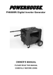
1
Generator/Air Compressor 2 in 1
Owner’s Manual
Thank you for purchasing our generator/air compressor. This manual provides information
regarding the operation and maintenance of this product. Please read this manual befor e using this
product.
We have made every effort to ensure the accuracy of the information in this manual. We reserve
the right to change this product at any time without prior notice.
Please keep this manual available to all users during the entire life of the generator.
TABLE OF CONTENTS
1. GENERAL SAFETY PROCEDURE……………………………………3
2. COMPONENTS………………………….………………………….6
3. PREPARING THE UNIT FOR USE………………………….................7
4. STARTING THE UNIT…………………………………………...……..12
5. USING THE GENERATOR/AIR COMPRESSOR.... ………………..……..13
6. STOPPING THE GENERATOR/AIR COMPRESSOR..…………...….……15
7. MAINTENANCE / CARE………………………………….……….…15
8. STORAGE / TRANSPORT PROCEDURES.………………..…………..... 20
9. TROUBLESHOOTING FOR GENERATOR………………………...…….21
10. TROUBLE SHOOTING FOR AIR COMPRESSOR…………………….…22
11. SPECIFICATIONS..………………….………………….……………23
12. WIRNG DIAGRAM FOR MODEL WITH/WITHOUT DC…..…..……….... 24
13.EXPOILED VIEW DARAWING...……………………………………… 26
14. PARTS LIST…………………….……………………………..………....27
2
1. GENERAL SAFETY PROCEDURE
Please familiarize yourself with the following safety symbols and words:
The safety alert symbol
is used with one of the safety words (DANGER, CAUTION, or
WARNING) to alert you to hazards. Please pay attention to these hazard notices both in this
manual and on the generator.
DANGER: Indicates a hazard that will result in serious injury or death if instructions are not
followed.
WARNING: Indicates a strong possibility of causing serious injury or death if instructions are not
followed.
CAUT ION: Indicates a possibility of personal injury or equipment damage if instructions are not
followed.
DANGER: This unit produces poisonous carbon monoxide gas when running.
This gas is both odorless and colorless. Even if you do not see or smell gas, carbon
monoxide may still be present. Breathing this poison can lead to headaches,
dizziness, drowsiness, and eventually death.
•
•
Use outdoors ONLY in non-confined areas.
Keep at least of 1 meter clearance on all sides to allow proper ventilation of the generator.
WARNING: This unit may emit highly flammable and explosive gasoline
vapors, which can cause severe burns or even death. A nearby open flame can lead
to explosion even if not directly in contact with gas.
• Do not operate near open flame.
• Do not smoke near the unit.
• Always operate on a firm, level surface.
• Always turn unit off before refueling. Allow unit to cool for at least 2 minutes
before removing fuel cap. Loosen cap slowly to relieve pressure in tank.
• Do not overfill gas tank. Gas may expand during operation. Do not fill to the top
of the tank.
• Always check for spilled gas before operating.
• Empty gasoline tank before storing or transporting the unit.
• Before transporting, turn fuel valve to off and disconnect spark plug.
3
WARNING: The generator of this unit produces powerful voltage, which can
result in electrocution.
• ALWAYS ground the generator before using it (see the “Ground the Generator”
portion of the “PREPARING THE UNIT FOR USE” section).
• Generator should only be plugged into electrical devices, either directly or with
an extension cord. NEVER connect to a building electrical system without a
qualified electrician. Such connections must comply with local electrical laws
and codes. Failure to comply can create a backfeed, which ma y result in serious
injury or death to utility workers.
• Use a ground fault circuit interrupter (GFCI) in highly conductive areas such as
metal decking or steel work. GFCIs are available in-line with some extension
cords.
• Do not use in rainy or wet conditions.
• Do not touch bare wires or receptacles (outlets).
• Do not allow children or non-qualified persons to operate.
WARNING: This unit produces heat when running. Temperatures near
exhaust can exceed 150o F (65 o C).
• Do not touch hot surfaces. Pay attention to warning labels on the generator
denoting hot parts of the machine.
• Allow the unit to cool several minutes after use before touching engine or areas
which heat during use.
• Plug individual appliances into the unit using heavy-duty, outdoor-rated cords
with a wire gauge adequate for the appliance load. Overloaded cords can cause
fires or equip ment damage. Don't use extension cords with exposed wire s or
worn shielding. Make sure the cords from the generator don't present a tripping
hazard. Don't run cords under rugs where heat might build up or cord damage
may go unnoticed.”
CAUTION: Misuse of this unit can damage it or shorten its life.
• Use this unit only for its intended purposes.
• Operate only on dry, level surfaces.
• Allow generator to run for several minutes before connecting electrical devices.
• Shut off and disconnect any malfunctioning devices from generator.
• Do not exceed the Wattage capacity of the generator by plugging in more
electrical devices than the unit can handle.
• Do not turn on electrical devices until after they are connected to the generator.
• Turn off all connected electrical devices before stopping the generator.
WARNING:
l
Shut off the compressor, disconnect air hoses, release air pressure from the tanks,
and allow the compressor a nd engine to cool before performing any maintenance
on this tool.
l
Adjust the Regulator to a pressure that does not exceed the maximum operating
pressure for your tool. Do not connect an air tool to this compressor if the
regulator is set for a higher press ure than the maximum recommended pressure
for that tool.
4
l
l
l
l
l
l
l
Do not remove or modify the factory installed Control Valve Assembly
Do not remove or modify the Safety Valve.
Open the Drain Valves every day after use. Water will accumulate in the tanks,
and if not drained can cause corrosion on the inside of the tanks. Corrosion may
weaken the tanks.
Do not open the Drain Valves more than four full turns. If more than 4 threads are
showing, the drain valves may be damaged or may blow out of the tank.
Do not attempt to repair or modify the Air Tanks. Welding, drilling or otherwise
modifying the tanks may weaken them and potentially cause leaks or explosion.
The compressor and engine are a source of ignition when they are running, and
after operation until they have cooled off. Do not spray or spill flammables in the
area of this tool. Flammables such as spray paint, solvents, gasoline, etc. may
ignite or explode if sprayed or spilled near or on this compressor or engine.
This compressor and engine will create loud and prolonged noise when in
operation. Do not remain near the compressor when it is in operation without
appropriate hearing protection. Wear ANSI-approved hearing protection
equipment when working near this compressor.
In addition to the above safety not ices, please familiarize yourself with the safety and hazard
markings on the unit
5
2. COMPONENTS
(1)Engine Switch-Use to start/stop engine
(2)Compressor Switch – Select to start and
stop the compressor
(3) Circuit Breaker24A- Push buttons that
protect the generator from electrical
overload.
(4)Circuit Breaker 20A - Push buttons that
protect the generator from electrical
overload.
(5) 120 V Receptacles- To connect electrical
devices that run 120 Volt, 60 Hz, single
phase, AC current.
(6) 120V Twistlock receptacle
(7)Indicators-Output indicator, overload
alarm indicator, low oil alarm indicator.
(8) Ground Terminal- Connect grounding
wires here to properly ground unit.
(9) Choke Lever- Adjusts the amount of air
let into the engine.
(10)Fuel Valve- Allows fuel to enter engine.
(11) Recoil Starter- Pull-cord for starting
engine.
(12) Fuel Cap - Access to the fuel tank for
adding fuel.
(13) Fuel Gauge - Indicates the amount of
fuel in the tank.
(14)Tank Pressure Gauge – Indicate s the
pressure in side the tank
(15)Output Pressure Gauge – Indicates the
output pressure
(16)Handle Lock – Use to lock the handle
(17)Pressure Regulator – Use to regulate the
output pressure
(18)Connector – Use to connect the air hose
for the air tools
(19) Spark Plug- Provides proper engine
ignition.
(20) Oil Fill and Dipstick- Location for
checking and f illing engine oil.
(21)Pressure Switch – Use to control the cut
out pressure
(22) Air Cleaner- a removable, cleanable,
sponge-like element that limits the amount of
dirt pulled into the engine.
(23)Drain Valve- Use to drain out the water
and dust inside the tank
(24)Safety Valve - Use to release the tank
pressure so as to prevent the tank from
bursting
(25) DC terminal : only for connecting 12V
DC device
(26) DC fuse -To protect DC from overload.
6
3. PREPARING THE UNIT FOR USE
If you are using the unit for the first time, there are a few steps you must take to prepare it for
operation:
Step 1 – Attach the wheels and foot bracket
1: Find the wheels, wheel axle, and cotter pin
2: Insert the axle to the wheels (see figure 1)
3: Insert the cotter pin to the end of the axle (see figure 2)
4: Attach other end of the axle and wheel to the frame, insert the cotter pin to the hole on the
frame.(see figure 3)
5: Repeat the four steps above to add the other wheel
Figure 1
Figure 2
Figure 3
6: Find the foot bracket.(see figure 4)
7: Attached the foot bracket to the bottom of the frame by screwing it inside, then fasten it by
using the wrench.
Figure 4
Figure 5
Step 2- Add engine oil
This unit requires engine oil to operate properly. The unit, when new from the package, contains
no oil in the crankcase. You must add the proper amount of oil before operating the unit for the
first time. This amount, which is equal to the oil capacity of the engine crankcase, can be found
on the chart in figure 6. When filling the engine with oil in the future, please refer to this chart.
GC3012HiD
600ml
Model number
Engine Oil capacity
Figure 6- Engine Oil Capacity
For general use, we recommend SAE 15W/40 4-stroke motor oil to fill the engine crankcase.
7
To add oil, follow these steps:
1. Make sure the unit is on a level surface.
2. Remove the back cover of the unit by unscrewing the two bolts on the back cover as
shown in figure 7
3. Unscrew the oil filler/dipstick cap from the engine as shown in figure 8.
4. Using a funnel, add the appropriate amount of oil, as found in figure 6, into the crankcase.
You will know the crankcase is full when the oil level has reached the lower lip of the
opening you have just poured the oil into (see figure 9).
5. Replace oil filler cap.
6. Attached the back cover to the unit and screw the two bolts
NOTE: Engine oil need to be added before you use this product, either for generator use
or air compressor use.
O pen Housing
Figure 7 – Removing the back cover Figure 8- Unscrewing the oil cap
Figure 9- Adding oil
Step 3-Add oil for air compressor
The air compressor of this unit requires oil to operate properly. You must add the proper amount
of oil before operating the air compressor for the first time. This amount, which is equal to the
oil capacity of the air compressor crankcase, can be found on the chart in figure 10. When filling
the engine with oil in the future, please refer to this chart.
Model number
Oil capacity for Air compressor
GC3012HiD
270ml
Figure 10- Oil Capacity for air compressor
For general use, we recommend SAE 15W/40 4-stroke motor oil to fill the air compressor
crankcase.
1. Make sure the unit is on a level surface.
2. Remove the right cover of the unit by unscrewing the two bolts on the back cover as
shown in figure 11
3. Unscrew the oil breather from the engine as shown in figure 12.
8
4. Using a funnel, add the appropriate amount of oil, as found in figure 10, into the
crankcase. Oil capacity should be between the “LOW” and “FULL” mark on the oil level
indicator (see figure 13). Do not ove rfill the crankcase.
5. Attached the back cover to the unit and screw the two bolts
Open Housing
Figure 11
Figure 12
Figure 13
Step 4- Add Gasoline
WARNING: Gasoline and gas fumes are highly flammable.
• Do not fill tank near an open flame.
•
Do not overfill. Always check for fuel spills.
To ensure that the unit runs smoothly use only FRESH, UNLEADED GAS WITH AN OCTANE
RATING OF 87 OR HIGHER. To add gasoline:
1. Make sure the unit is on a level surface.
2. Unscrew gas cap and set aside (NOTE: the gas cap may be tight and hard to unscrew).
3. Slowly add unleaded gasoline to the fuel tank. Be careful not to overfill. Please refer to the
chart in figure 14 to find the gas capacity of your unit model. The fuel gauge on the top of
the unit indicates how much gasoline is in the generator gas tank. NOTE: Gas can
expand. Do not fill the gas tank to the very top.
4. Replace fuel cap and wipe up any spilled gasoline with a dry cloth.
IMPORTANT:
• Never use an oil/gasoline mixture.
• Never use old gas.
9
•
•
Avoid getting dirt or water in the fuel tank.
Gas can age in the tank and make it hard to start up the generator in the future. Never store
generator for extended periods of time with fuel in the tank.
GC3012HiD
14 L (3.96 gallons)
Model number
Gas tank capacity
Figure 14- Gas Tank Capacity
Step 5- Ground the Generator of this unit
WARNING: Failure to properly ground the generator can result in electrocution.
Ground the generator by tightening the grounding nut against a grounding wire (see figure 15).
A generally acceptable grounding wire is a No. 12 AWG (American Wire Gauge) stranded copper
wire. This grounding wire should be connected at the other end to a copper or brass grounding
rod that is driven into the earth.
Grounding codes can vary by location. Please contact a local electrician to check the grounding
regulations for your area.
Figure 15- Grounding nut location
Subsequent Use of the Generator
If this is not your first time using the generator there are still steps you should take to prepare it for
operation.
IMPORTANT: At this point you should be familiar with the procedures described in the
first portion of this section entitled “Using the Generator for the First Time.” If you have
not yet read this section, go back and read it now.
Step 1- Check the Oil
I: Check the oil for generator
The generator is equipped with an automatic shutoff to protect it from damage due to low oil.
Nonetheless, you should check the oil level of the engine before each use to ensure that the engine
crankcase has a sufficient amount. To check the oil level:
1. Make sure the generator is on a level surface.
10
2. Unscrew the oil filler/dipstick cap.
3. With a dry cloth, wipe the oil off of the stick on the inside of the cap.
4. Insert the dipstick as if you were replacing the cap and then remove again. There should
now be oil on the stick. If there is no oil on the stick, or oil only at the very end of the
stick, you should add oil until the engine crankcase is filled
5. Be sure to replace cap when finished checking oil.
NOTE: The oil capacity for your generator can be found in the “Specifications” section of this
manual
II: Check the oil for air compressor
Check the oil indicator to see if the oil level is within the required range, add oil if the oil level is
low. (see figure 13)
Step 2 – Check the Gas Level
Before starting the generator, check to see that there is sufficient gasoline in the gas tank. The fuel
gauge on top of the generator will indicate the gas level in the tank. Add gas if necessary
according to the steps in the “Adding Gasoline” portion of the “Maintenance” section.
WARNING: Gasoline and gasoline fumes are highly flammable.
• Do not fill tank near an open flame.
• Always allow engine to cool for several minutes before refueling.
• Do not overfill (check the “Specifications” section for the tank capacity of your
generator). Always check for fuel spills.
IMPORTANT:
• Use only UNLEADED gasoline with an octane rating of 87 or higher.
• Do not use old gas.
• Never use an oil/gasoline mixture.
• Avoid getting dirt or water in the fuel tank.
• Never store generator for extended periods of time with fuel in the tank.
Step 3- Ground the Generator
WARNING: Failure to properly ground the generator can result in electrocution.
Ground the generator by tightening the grounding nut against a grounding wire (see figure 6). A
generally acceptable grounding wire is a No. 12 AWG (American Wire Gauge) stranded copper
wire. This grounding wire should be connected at the other end to a copper or brass grounding
rod that is driven into the earth.
Grounding codes can vary by location. Please contact a local electrician to check the grounding
regulations for your area.
Step 4- Check the safety Valve
11
Pull the ring on the safety valve to make sure that the safety valve operates freely. If the valve is
stuck or does not operate smoothly, it must be replaced with the same type of valve.
4. STARTING THE UNIT
Before starting the unit, make sure you have read and performed the steps in the
“Preparing the Generator for Use” section of this manual.
CAUTION: Disconnect all electrical loads from the generator before attempting to
start.
To start your generator/air compressor, perform the following steps:
1. Make sure no electrical devices are connected to the generator. Such devices can make it
difficult for the engine to start.
2. Check that the generator is pr operly grounded (see section “Ground the Generator”).
3. Turn the fuel valve to the “on” position (see figure 16).
4. Move the choke rod to the “closed” position (see figure 17).
5. Set the engine switch to the “on” position.
6. Pull on the recoil starter handle slowly until a slight resistance is felt (see figure 18).
Then pull quickly to start the engine. Return cord gently into the machine. Never allow
the cord to snap back.
7. If engine fails to start, adjust the position of the choke rod and repeat step 6. NOTE:
After repeated attempts to start the engine, please consult the troubleshooting guide before
attempting again. If problems persist please contact the dealer.
8. Once the engine has started and run for about a minute, move the choke rod about half way
towards the “open” position. Wait another 30 seconds and then move the choke rod all
the way to the “open” position.
9. Allow the generator to run for several minutes before attempting to connect any electrical
devices.
Figure 16- Fuel Valve in the “on” position
Figure 17- Choke in the “closed” position
C start handle
Figure 18- Pulling the start cord
12
5. USING THE GENERATOR / AIR COMPRESSOR
This Unit has three working mode. You can run the generator singly, run the air
compressor singly and run them together.
I: Air Compressor working mode
After the unit is started, select the compressor selector to on position (see figure 19) and not to
plug in any electrical device, then this unit runs with only the air compressor working.
II: Generator working mode
After the unit is started and the air tank is loaded with a full tank of air, select the compressor
selector to off position (see figure 20), then this unit runs with only the generator working. Allow
the engine to run for several minutes and plug in the electrical device to the voltage outlet.
NOTE: Air tank need to be pumped with a full tank of air before select the compressor to
off position.
III: 2 in 1 mode
Select the compressor selector to on position (see figure 19), allow the engine to run for several
minutes, and plug in the electrical device to the voltage outlet. You can run the generator and air
compressor together.
Figure 19
Figure 20
CAUTION: Please familiarize yourself with the markings on the panel before connecting
electrical devices.
You may connect electrical devices running on AC current according to their wattage
requirements.
The rated wattage corresponds to the maximum wattage the generator can output on a continuous
basis.
Model Number
Rated(Running) Wattage
GC3012HiD
2600
Figure 21- generator wattage
The total running wattage requirement of the electrical devices connected to the generator should
not exceed the rated wattage of the generator itself. To calculate the total wattage requirement of
the electrical devices you wish to connect, find the rated (or running) wattage of each device.
13
This number should be listed somewhere on the device or in its instruction manual. If you cannot
find this wattage, you may calculate it by multiplying the Voltage requirement by the Amperage
drawn:
Watts= Volts x Amperes
Once you have found the rated wattage requirement of each electrical device, add these numbers
to find the total rated wattage you wish to draw from the generator. If this number exceeds the
rated wattage of the generator, DO NOT connect all these devices. Select a combination of
electrical devices, which has a total rated wattage lower than or equal to the rated wattage of the
generator.
CAUTION- The generator can run at its surge wattage capacity for only a short time.
Connect electrical devices requiring a rated (running) wattage equal to or less than the
rated wattage of the generator. Never connect devices requiring a rated wattage equal to
the surge wattage of the generator.
5.1 Steps of Using the generator
1.Start the engine and make sure the output indicator (green) comes on and other red light are off.
2. Make sure that the appliance to be used is switched off, and plug in the appliance.
5.2 Output and Overload Indicators, low engine oil Indicator
The out indicator light (green) will remain ON during normal operating conditions.
If the generator is overloaded, or if there is a short in the connected appliance, the output indicator
light (green) will go OFF, the overload indicator light (red) will go ON and current to the
connected appliance will be cutted off.
Stop the engine if the overload indicator light (red) comes ON and check overload reason
Check engine oil if the oil indicator (Red) turns ON.
NOTE:
n Before connecting an appliance to the generator, check that it is in good order, and that its
electrical rating does not exceed that of the generator. Then connect the power cord of the
appliance, and start the engine.
n When an electric motor is started, both the overload indicator light (red) and the output
indicator light (green) lights may go on simultaneously. This is normal if the overload
indicator light(red) goes off after about four (4) seconds. If the overload indicator light(red)
stays on, please contact with the dealer.
5.3 Low oil alert system
The low oil alert system is designed to avoid the damage of engine due to insufficient oil inside
the crankcase. The low oil alert system is actuated and automatically shut off the engine when the
oil level is about to be lower than the safety level. When the low oil alert system is actuated, low
oil indicator (Red) flashes if the operator attempts to start the engine again, in this case the engine
could not be started. ADD OIL!
14
6. STOPPING THE GENERATOR/AIR COMPRESSOR
To stop this unit:
1. Turn off, then unplug all connected electrical devices.
2. Allow the unit to run for several more minutes with no electrical devices connected. This
helps stabilize the temperature of the generator.
3. Set the engine switch to the “off” position.
4. Turn the fuel valve to the “off” position.
5. Open the drain valve to drain out the air and water
WARNING: Allow the generator to cool for several minutes before touching areas that
become hot during use.
CAUTION: Allowing gas to s it in the generator tank for long periods of time without use
can make it difficult to start the generator in the future. Never store generator for extended
periods of time with fuel in the tank.
7. MAINTENANCE / CARE
Proper routine maintenance of your generator will help prolong the life of your machine. Please
perform maintenance checks and operations according the schedule in figure 22.
CAUTION: Never perform maintenance operations while the unit is running.
Recommended Maintenance Schedule
each use
Engine oil
Compressor oil
check level
Engine Air cleaner
fuel filter cup
every
every month
months or
months or
year or
or 20 hrs
50 hrs
100 hrs
300 hrs
x
x
replace
check
every 6
x
replace
check level
every 3
x
x
clean
x
clean
x
spark plug
check/ clean
x
gas tank
check gas level
x
clean
Safety Valve Ring
x
check
each week
Figure 22- Recommended maintenance schedule
15
Cleaning the Gene rator/Air compressor
Always try to use your generator/air compressor in a cool dry place. In the event your generator
becomes dirty you may clean the exterior with one or more of the following:
-
a damp cloth
a soft brush
a vacuum
pressurized air
Never clean your generator/air compressor with a bucket of water or a hose. Water can get
inside the working parts of the generator and cause a short circuit or corrosion.
Checking the Oil
The generator is equipped with an automatic shutoff to protect it from running on low oil.
Nonetheless, you should check the oil level of the generator before each use to ensure that the
generator crankcase has a sufficient amount. To check the oil level:
1. Make sure the generator is on a level surface.
2. Unscrew the oil filler/dipstick cap (see figure 23).
3. With a dry cloth, wipe the oil off of the stick on the inside of the cap.
4. Insert the dipstick as if you were replacing the cap and then remove again. There should
now be oil on the stick. If there is no oil on the stick, or oil only at the very end of the
stick, you should add oil until the engine crankcase is filled. See “Changing/ Adding
Oil” in this section.
5. Be sure to replace cap when finished checking oil.
6. Check the oil level of the air compressor by watching if the oil level is with in the range
between “low” and “full” mark (see figure 23). If it is below the “low” mark, you should
add the oil until the compressor crankcase is filled. See “Changing/ Adding Oil” in this
section.
Oil filler cap
Oil filler hole
Figure 23- Checking the oil
16
Changing/ Adding Oil
Changing/Adding oil for generator
You should check the oil level of your generator according to the maintenance schedule in figure
22. When the oil level is low you will need to add oil until the level is sufficient to run the
generator.
The oil capacity of your generator engine is listed in figure 24.
Model number
Engine oil capacity
GC3012HiD
600ml
Figure 24- Engine Oil Capacity.
It is only necessary to drain the oil from the crankcase if it has become contaminated wit h water or
dirt. In this case, you can drain the oil from the generator according to the following steps:
1. Place a bucket underneath the generator to catch oil as it drains.
2. Remove the back cover of this unit.
3. Using a 10 mm hex wrench, unscrew the oil drain plug, which is located on the crankcase
underneath the oil filler/dipstick cap (see figure 25). Allow all the oil to drain from the
generator.
4. Replace the oil drain plug and tighten with a 10 mm hex wrench.
To add oil to the engine crankcase, follow these steps:
1. Make sure the generator is on a level surface.
2. Unscrew the oil filler/dipstick cap from the engine as shown in figure 14 above.
3. Using a funnel, add high detergent motor oil to the crankcase. We recommend SAE 30W
4-stroke motor oil for general use. When full, the oil level should come close to the top of
the oil fill opening (see figure 26).
Filler cap
Drain plug
Figure 25- Draining oil
Figure 26- Adding oil
NOTE: Never dispose of used motor oil in the trash or down a drain. Please call your local
recycling center or auto garage to arrange oil disposal.
Changing/Adding oil for generator
You should check the oil level of the compressor according to the maintenance schedule in figure
22. When the oil level is low you will need to add oil until the level is sufficient to run the
generator.
17
The oil capacity of your generator engine is listed in figure 27.
1.
2.
3.
4.
5.
GC3012HiD
Model number
270ml
Compressor oil capacity
Figure 27
Make sure the unit is on a level surface.
Remove the right cover of the unit by unscr ewing the two bolts on the back cover as
shown in figure 28
Unscrew the oil breather from the engine as shown in figure 29.
Using a funnel, add the appropriate amount of oil, as found in figure 10, into the
crankcase. Oil capacity should be between the “LOW” and “FULL” mark on the oil level
indicator (see figure 23). Do not overfill the crankcase.
Attached the back cover to the unit and screw the two bolts
Open Housing
Figure 28
Figure 29
Air Cleaner Maintenance
Routine maintenance of the air cleaner helps maintain proper air flow to the carburetor.
Occasionally check that the air cleaner is free of excessive dirt.
1.
2.
3.
4.
5.
6.
Unscrew the 4 bolts of the air cleaner cover (see figure 30).
Remove the sponge -like elements from the casing.
Wipe the dirt from inside the empty air cleaner casing
Wash the sponge -like elements in household detergent and warm water. Allow to dry.
Soak the dry elements in engine oil. Squeeze out any excess oil.
Replace the sponge -like elements in the air cleaner casing and replace the cover.
18
Figure 30- Removing the air cleaner casing.
Spark Plug Maintenance
The spark plug is important for proper engine operation. A good spark plug should be intact,
free of deposits, and properly gapped. To inspect your spark plug:
1. Pull on the spark plug cap to remove it.
2. Remove the back cover of the generator.
3. Unscrew the spark plug from the generator using the spark plug wrench included with this
product (see figure 31).
4. Visually inspect the spark plug. If it is cracked or chipped, discard and replace with a
new spark plug. We recommend using a spark plug such as F7RTC-LG.
5. Measure the plug gap with a gauge (see figure 32). The gap should be 0.7-0.8mm
(0.028-0.031in).
6. If you are re-using the spark plug, use a wire brush to clean any dirt from around the spark
plug base and then re-gap the spark plug..
7. Screw the spark plug back into its place on the generator using the spark plug wrench.
Replace the spark plug cap.
19
Figure 31- Removing the spark plug
Figure 32- Measuring the spark plug gap
Emptying the Gas Tank
Before storing your generator for extended periods of time, you should drain your generator of
gasoline. To drain the generator of gas:
1. Turn the fuel valve to the “off” position.
2. Remove the fuel filter cup (see “Fuel Filter Cup Cleaning” earlier in this section).
3. Empty the fuel filter cup of any fuel.
4. With a receptacle underneath the generator to catch the gas, turn the fuel valve to the “on”
position. Drain all the gas from the generator.
5. Turn the fuel valve to the “off” position.
6. Replace the fuel filter cup.
7. Store the emptied gasoline in a suitable place.
CAUTION: Do not store fuel from one season to another.
8. STORAGE / TRANSPORT PROCEDURES
CAUTION: Never place any type of storage cover on the generator while it is still hot.
When transporting or storing your generator for extended periods of time:
• Empty the gas tank (see “Emptying the Gas Tank” in the “Maintenance” section).
• Disconnect the spark plug.
• Do not obstruct any ventilation openings.
• Keep the generator in a cool dry area.
20
9. TROUBLESHOOTING FOR GENERATOR
If the engine do not start, please check
N
If any fuel in the tank
Add fuel
Y
N
Turn the switch to on position
If engine switch is no?
Y
N
If fuel valve is on?
Turn on the valve
Y
N
Add oil
If enough oil in the engine?
Y
If spark from the spark plug
No spark
N
Contac the authorized
Replace plug
dealer
How to check:
1) Remove the spark plug cap and clean
Be sure there is no spilled fuel around
any dirt from around the spark plug.
the spark plug. Spilled fuel may
2) Remove the spark plug and install the spark
ignite.
plug in the plug cap.
3) Set the plug side electrode on the cylinder head to ground.
4) Crank the engine, sparks should jump across the gap.
Warning
If the fuel reaches carburetor
How to check :
1) Turn off the fuel valve and lossen the
drain screw.
If the engine still does not
2) Fuel should flow from the drain when
start, contact the authorized
the fuel valve is turned on.
dealer.
If the
appliance does not operate, please check
If the output indicator is ON?
N
N
If the overload indicator light is ON?
Contact the authorized dealer
Y
Y
Check the electrical appliance or equipment for any N
defects.
21
Contact the authorized dealer
10. TROUBLE SHOOTING FOR AIR COMPRESSOR
Problem
Cause
Correction
No indication on the pressure
Magnetic valve is not on
Select the circuit breaker to on
Pressure switch is at off position
position
Select the pressure switch to on
gauge
position
Inlet and outlets valve plate are
installed wrong
Install the inlet and outlet valve
plates again
Crankshaft,
damage
Replace
connecting
rod
Pressure gauge reading too Pressure switch is set too high
high
Pressure switch not work
Pressure switch trip when the
compressor is at off position
Reset the pressure value of the
pressure switch
Air cleaner not in good condition
Replace
Magnetic
wrong
Connect the magnetic valve
again
valve
is
connected
Pressure switch damage
Replace
Air cleaner damage
Replace air cleaner
Air flowing system leakage
Check and fasten fitting and
sealing of the air flowing system
Oil leakage at the end cap
Leaking gasket
Replace the rubber gasket
No pressure output when the
Magnetic valve damage
Replace
compressor selector is at on
position.
22
11.SPECIFICATIONS
Generator
Condition
Air
compressor
working mode
2 in 1 mode
2.6
/
1.8
DC Output (Optional)
12V/8A
12V/8A
12V/8A
Rated Frequency( Hz)
60
/
60
Rated Voltage ( V)
120
/
120
Rated Amperage ( A)
23.3
/
15
Rated Speed( r/min)
3600
/
3600
Air Tank Capacity( Gallon)
/
3.5
3.5
Cut-In Pressure( PSI)
/
90
90
Cut-Out Pressure( PSI)
/
125
125
4.1SCFM
4.1SCFM
5.0SCFM
5.0SCFM
Type
Generator
working mode
Rated Output( kW)
90PSI
/
Air Compressor Flow
40PSI
/
Engine
Model No.
Engine Type
Displacement( Bore x Stroke )
Compression Ratio
Rated Power? kW/(r/rpm)?
Rated speed( rpm)
Ignition Type
Spark Plug
Starting Mode
Fuel Type
Fuel Consumption Rate( g/kW.h)
Oil Type
170F
OHV
208cc
8.5:1
3.8/ 3600
3600
TCI
F7RTC-LG
Recoil Start
90#
385g/kWh
15W/40
Fuel Tank Capacity( L)
Dimension( Length x Width x Height) (mm)
Net Wight? kg?
14
458X584X472
55
23
12.WIRNG DIAGRAM FOR MODEL WITH DC
24
WIRNG DIAGRAM FOR MODEL WITHOUT DC
25
13. EXPOILED VIEW DRAWING
26
14. PARTS LIST
Item
No.
Description
Qty
Item
No.
Description
Qty
1
Air Tank Assembly
1
40
1/4 Connect
1
2
Drain Valve
2
41
Regulator
1
3
Check valve
1
42
Pressure Gauge Base
1
4
Safety valve
1
43
Pressure Gauge
2
5
Elbow
2
44
High Block
2
6
Flange Bolt M8*16
2
45
Engine Base Support II
1
7
Socket head screw M8*10
1
46
Flange Bolt M6*40
2
8
Spring washer? 8
3
47
Spring
1
9
Plain washer? 8*20*2
1
48
Rubber Plug
1
10
Pressure switch connecting
1
49
End Cap
1
11
Elbow
9
50
O-Ring
2
12
Shield A
1
51
Piston
1
13
Splitpin
4
52
Pressure adjusting spring
1
14
Wheel
2
53
Regulator cover
1
15
Axle
2
54
Flange Bolt M5*16
4
16
M8 Nut
8
55
Quick Connector
2
17
Frame
1
56
Invertor Baffle
1
18
Frame Support
2
57
Invertor Bracket
1
19
Plain washer ? 8*24*2
2
58
Engine
1
20
Rubber Foot
2
59
Seal
1
21
Plain washer? 6*18*2
2
60
Pump Crankcase
1
22
Flange Bolt M6*20
2
61
Crack Shaft
1
23
Control panel Assy
1
62
Socket head screw M6*20
1
24
Flange Bolt M6*12
12
63
Flange Bolt M8*16
4
25
Paper washer? 6
10
64
Rubber Seal
1
26
Solenoid Valve
1
65
End Cover
1
27
Plug Screw
2
66
Plain Washer ? 6
8
28
Socket head screw M4*15
2
67
Flange Bolt M8*20
4
29
Air Filter
1
68
Cross recess panheadscrew M5*10
1
30
Pressure switch
1
69
Connecting Rod
1
31
Shield B
1
70
Check Ring
2
32
Bumper A, Engine
1
71
Piston Pin
1
33
Bumper B, Engine
1
72
Piston
1
34
Plain washer ? 8
4
73
Oil Ring
1
35
Engine Base Support I
1
74
Compression Ring
2
36
Bolt M8*40
2
75
Cylinder gasket
1
37
Engine Base
1
76
Socket head screw M8*30
2
38
Invertor
1
77
Cylinder
1
39
Tee Joint
1
78
Valve plate gasket
1
27
Item
Description
No.
Qty
Item
Description
No.
Qty
79
Valve Plate
2
89
Handle
1
80
Valve
2
90
Rubber Nut M12
2
81
Metal gasket
1
91
Plain Washer ? 16
4
82
Head gasket
1
92
Handle connecting rubber
2
83
Male Coupling
1
93
Fuel Tank Assy
1
84
Cylinder Cap
1
94
Flange Bolt M6*30
4
85
Spring Washer ? 6
4
95
Plain washer? 6*20*2
4
86
Socket head screw M6*50
4
96
Bumper C, Engine
1
87
handle rod
1
97
Bumper D, Engine
1
88
handle lock
1
28