1
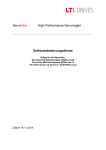
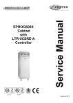
SOLO PLUS
CEILING MOUNTED UNITS
2001 to 2009
ISO 14001
ISO 9001
SOLO PLUS UNITS
Contents
Page
Introduction
Model Table
Foster Spares Information and Prices
Environmental Management Policy
Disposal Requirements
Dimensions, Location & Installation
Technical Data Ceiling Mount Units
Access to the Unit Compartment and Evaporator Housing
1
1
1 to 2
2
2
3
4
5
Ceiling Mounted Solo Units with the Serial Number Ending in ’H’.
Controller Operation and Parameter Access
Alarms and Warnings
Controller Reset after Data Error
Air and Defrost Probe Resistance Values
Wiring Diagrams
5 to 14
5 to 7
8
8
8
9 to 14
Ceiling Mounted Solo Units with the Serial Number Ending in ’I’.
Controller Operation, Parameter Access and Parameter List
Alarms and Warnings
Wiring Diagram Code Identifications
Wiring Diagrams
15 to 21
15 to 17
18
18
19 to 21
Controller Operation for Ceiling Mounted Solo Units with the Serial Number Ending in ‘J’
Controller Operation, Parameter Access and Parameter List
Alarms and Warnings
Wiring Diagram Code Identifications
Wiring Diagrams
22 to 27
22 to 25
25
25
26 to 27
Introduction
It is important to note that all work should be carried out by a competent person.
Solo plus is a range of self contained refrigeration units for small and large coldrooms comprising hot gas defrost
with crankcase protection, capillary control and hot gas vaporisation.
The systems are pre-charged with refrigerant and pre-wired ready for installation into a coldroom with only
electrical connections to be made.
Under certain conditions a drain pipe may be required to drain any excess defrost water to an external source
Routine Maintenance
In order to keep the unit operating reliably and efficiently periodical cleaning of the condenser is necessary. (The
frequency being determined by site conditions)
This operation is to be carried out with the unit turned OFF. We advise the use of an air jet blowing from inside to
the outside. If an air jet is not available then use a soft long haired brush on the outside of the condenser taking
care not to damage the fins.
Warning: Condenser fins have sharp edges so care must be taken to avoid injury
Model Table
SP1HC
SP1HC
SP1HC
SP1LC
SP2HC
SP2HC
SP2HC
SP2LC
Model
SP3HC
SP3HC
SP3HC
SP3LC
SP4HC
SP4HC
SP4HC
SP5HC
SP5HC
SP5HC
NOTE: Nomenclature “C” refers to Ceiling Model
As each model operates at different temperatures it will be necessary to set the required operating temperature.
See operating instruction on pages 5 to 6, 15 to 16, 22 to 23 and parameter list on pages 7, 17 and 24 to 25.
For Foster spare parts information and prices go to www.fosterrefigerator.co.uk.
Once you have accessed the home page select ‘Spares’ from the menu on the left hand side of the page.
The screen will change to the ‘Welcome to Foster WebSpares’ page.
Click on ‘Browse Product’ and from there and select the product range you require followed by the model.
1
.
Select the part you require from the list or use the mouse pointer to highlight the part from the drawing, click the left
mouse button for the part number, description and price to be displayed on the right hand side of the screen.
For service manuals click on Service Documentation and select from the list.
Environmental Management Policy.
Product Support and Installation Contractors
Foster Refrigerator recognises that its activities, products and services can have an adverse impact upon the
environment.
The organisation is committed to implementing systems and controls to manage, reduce and eliminate its adverse
environmental impacts wherever possible, and has formulated an Environmental Policy outlining our core aims. A
copy of the Environmental Policy is available to all contractors and suppliers upon request.
The organisation is committed to working with suppliers and contractors where their activities have the potential to
impact upon the environment. To achieve the aims stated in the Environmental Policy we require that all suppliers
and contractors operate in compliance with the law and are committed to best practice in environmental
management.
Product Support and Installation contractors are required to:
1. Ensure that wherever possible waste is removed from the client’s site, where arrangements are in place all
waste should be returned to Foster Refrigerator’s premises. In certain circumstances waste may be disposed
of on the client’s site; if permission is given, if the client has arrangements in place for the type of waste.
2. If arranging for the disposal of your waste, handle, store and dispose of it in such a way as to prevent its
escape into the environment, harm to human health, and to ensure the compliance with the environmental law.
Guidance is available from the Environment Agency on how to comply with the waste management ‘duty of
care’.
3. The following waste must be stored separately from other wastes, as they are hazardous to the environment:
refrigerants, polyurethane foam, oils.
4. When arranging for disposal of waste, ensure a waste transfer note or consignment note is completed as
appropriate. Ensure that all waste is correctly described on the waste note and include the appropriate six-digit
code from the European Waste Catalogue. Your waste contractor or Foster can provide further information if
necessary.
5.
Ensure that all waste is removed by a registered waste carrier, a carrier in possession of a waste management
licence, or a carrier holding an appropriate exemption. Ensure the person receiving the waste at its ultimate
destination is in receipt of a waste management licence or valid exemption.
6. Handle and store refrigerants in such a way as to prevent their emission to atmosphere, and ensure they are
disposed of safely and in accordance with environmental law.
7. Make arrangements to ensure all staff who handle refrigerants do so at a level of competence consistent with
the City Guilds 2078 Handling Refrigerants qualification or equivalent qualification.
8.
Ensure all liquid substances are securely stored to prevent leaks and spill, and are not disposed of to storm
drains, foul drain, surface water to soil.
DISPOSAL REQUIREMENTS
If not disposed of properly all refrigerators have components that can be harmful to the environment. All old
refrigerators must be disposed of by appropriately registered and licensed waste contractors, and in accordance
with national laws and regulations.
2
Dimensions.
Location & Installation
Ceiling Mount Solo Units Power Absorption Table
Model
Electrical
Supply
Compressor
SP1HC
SP2HC
SP3HC
SP4HC
SP5HC
SP2LC
SP3LC
SP4LC
230/1/50
230/1/50
230/1/50
400/3/50
400/3/50
230/1/50
400/3/50
400/3/50
CAJ9480Z/F/CSR
CAJ9510Z/F/CSR
CAJ9513Z/FCSR
TAJ4517Z/T
MTZ28JE4
CAJ2464Z/F/CSR
TFH2480Z/T
TFH2511ZT
3
Max
Amp
7.90
8.40
12.00
5.90
5.60
11.30
5.80
6.80
Unit Absorption
Start
Run
Amp
Amp
25.00
4.30
32.00
5.0
34.00
6.30
22.00
4.30
24.00
7.20
42.00
5.50
27.00
4.20
32.00
4.80
KW
0.70
0.80
1.00
1.50
2.30
0.90
1.50
2.00
CEILING MOUNT SOLO PLUS TECHNICAL DATA
STORAGE TEMP +10°C
Foster
Model No
SP 1HC
SP 2HC
SP 3HC
SP 4HC
SP 5HC
Ref
Gas
R404A
R404A
R404A
R404A
R404A
Qty
Grms
0.54
0.60
0.73
0.70
1.10
Capillary size
No x exDia X intDia x Len
1 x 1,63 x 2,90 x L 2200
1 x 1.83 x 3,25 x L 3100
2 x 1,83 x 3,25 x L 3100
2 x 1,98 x 3,50 x L 2900
2 x 1,98 x3,50 x L 2000
STORAGE TEMP +1/4°C
STORAGE TEMP 0/-2°C
STORAGE TEMP –18/-21°C
Foster
Model No
SP 1HC
SP 2HC
SP 3HC
SP 4HC
SP 5HC
Foster
Model No
SP 1HC
SP 2HC
SP 3HC
SP 4HC
SP 5HC
Foster
Model No
SP 1LC
SP 2LC
SP 3LC
Ref
Gas
R404A
R404A
R404A
R404A
R404A
Qty
Grms
0.54
0.60
0.73
0.70
1.10
Capillary size
No x exDia X intDia x Len
1 x 1,6 3x 2,90 x L 2200
1 x 1.83 x 3,25 x L 3100
2 x 1,83 x 3,25 x L 3100
2 x 1,98 x 3,50 x L 2900
2 x 1,98 x3,50 x L 2000
Ref
Gas
R404A
R404A
R404A
R404A
R404A
Qty
Grms
0.54
0.60
0.73
0.70
1.10
Capillary size
No x exDia X intDia x Len
1 x 1,63 x 2,90 x L 2200
1 x 1.83 x 3,25 x L 3100
2 x 1,83 x 3,25 x L 3100
2 x 1,98 x 3,50 x L 2900
2 x 1,98 x3,50 x L 2000
Ref
Gas
R404A
R404A
R404A
Qty
Grms
0.42
0.84
0.96
Capillary size
No x exDia X intDia x Len
1 x 1,49 x 2,80 x L 1900
1 x 1,98 x 3,50 x L 3000
2 x 1,63 x 2,90 x L 2900
STORAGE TEMP +10°C
Foster Model
No
Nom
HP
SP 1HC
SP 2HC
SP 3HC
SP 4HC
SP 5HC
0.625
0.75
1
1.2
2
HP
Cut Out
Press.
Bar
------------------28
28
HP
Cut In
Press.
Bar
---------------------23
23
Suction
Valve
Press.
Bar
-------------------------------
HP
Cut In
Press.
Bar
---------------------23
23
Suction
Valve
Press.
Bar
-------------------------------
Noise
Level
dBa
59
60
60
60
63
Heat
Rejected
Max Watts
@ 32°C
2300
2675
3750
4200
7200
Room
Vent.
m³/ h #
Air
Air Vol
Watts
32°C Ambient
Room
Cap. m³
Watts
43°C Ambient
Room
Cap. m³
Throw
mts
m³/ h
750
750
1400
1400
1500
1500
1750
2600
2900
5200
10
12
20
28
56
1400
1600
2200
2700
4600
7
10
16
22
48
3
3
3.5
3.5
6
550
550
1100
1100
2300
Air
Air Vol
Nominal
Volts
Electrical
Phase
Hz
230
230
230
400
400
1
1
1
3
3
50
50
50
50
50
Electrical
Phase
Hz
230
230
230
400
400
1
1
1
3
3
50
50
50
50
50
Volts
Electrical
Phase
230
230
230
400
400
1
1
1
3
3
50
50
50
50
50
Volts
Electrical
Phase
Hz
230
400
400
1
3
3
50
50
50
Volts
Electrical
Phase
Hz
230
400
400
1
3
3
50
50
50
Amps
Watts
4.4
5.2
6.9
4.4
5.1
700
800
1100
1500
2100
Condensate
Vaporisation
Net.
Wt. Kg
Gross
Wt.
Kg
Auto
Auto
Auto
Auto
Auto
59
59
74
75
93
90
90
114
115
139
Net.
Wt. Kg
Gross
Wt.
Kg
Auto
Auto
Auto
Auto
Auto
59
59
67
75
93
90
90
114
115
139
Condensate
Vaporisation
Net.
Wt. Kg
Gross
Wt.
Kg
Hot Gas
Hot Gas
Hot Gas
Hot Gas
Hot Gas
Auto
Auto
Auto
Auto
Auto
59
59
74
75
93
90
90
114
115
139
Defrost
Type
Condensate
Vaporisation
Net.
Wt. Kg
Gross
Wt.
Kg
Hot Gas
Hot Gas
Hot Gas
Auto
Auto
Auto
68
87
102
99
118
142
Defrost
Type
Condensate
Vaporisation
Net.
Wt. Kg
Gross
Wt.
Kg
Hot Gas
Hot Gas
Hot Gas
Auto
Auto
Auto
68
87
102
99
118
142
Defrost
Type
Hot Gas
Hot Gas
Hot Gas
Hot Gas
Hot Gas
STORAGE TEMP +1/4°C
Foster
Model No
Nom
HP
SP 1HC
SP 2HC
SP 3HC
SP 4HC
SP 5HC
0.625
0.75
1
1.2
2
HP
Cut Out
Press.
Bar
---------------------28
28
Noise
Level
dBa
59
60
60
60
63
Heat
Rejected
Max Watts
@ 32°C
1950
2200
2850
3350
5700
Room
Vent.
m³/ h #
32°C Ambient
Watts
750
750
1400
1400
1500
1150
1350
1900
2300
4100
Room
Cap. m³
7
9
17
20
46
43°C Ambient
Watts
1050
1250
1600
2050
3600
Room
Cap. m³
5
6
10
12
28
Throw
mts
3
3
3.5
3.5
4
Volts
m³/ h
550
550
1100
1100
2300
Nominal
Amps
Watts
4.4
5.2
6.9
4.4
5.1
700
800
1100
1500
2100
Defrost
Type
Hot Gas
Hot Gas
Hot Gas
Hot Gas
Hot Gas
Condensate
Vaporisation
STORAGE TEMP 0/-2°C
Foster
Model No
Nom
HP
HP
Cut Out
Press.
Bar
HP
Cut In
Press.
Bar
Suction
Valve
Press.
Bar
Noise
Level
dBa
Heat
Rejected
Max Watts
@ 32°C
Room
Vent.
m³/ h #
Watts
SP 101HW
SP 2HC
SP 3HC
SP 4HC
SP 5HC
0.625
0.75
1
1.2
2
------------------------28
28
---------------------23
23
-------------------------------
59
60
60
60
63
1750
2000
2650
3150
5100
750
750
1400
1400
1500
1050
1200
1700
2000
3600
32°C Ambient
Room
Cap. m³
6
7
12
15
36
43°C Ambient
Watts
925
1100
1450
1700
3200
Room
Cap. m³
4
5
9
12
26
Air
Throw
mts
3
3
3.5
3.5
6
Air Vol
Nominal
Hz
Air Vol
550
550
1100
1100
2300
Amps
Watts
4.4
5.2
6.9
4.4
5.1
700
800
1100
1500
2100
Defrost
Type
STORAGE TEMP –18/-21°C
Foster
Model No
Nom
HP
HP
Cut Out
Press.
Bar
HP
Cut In
Press.
Bar
Suction
Valve
Press.
Bar
Noise
Level
dBa
Heat
Rejected
Max Watts
@ 32°C
Room
Vent.
m³/ h #
Watts
SP 2LC
SP 3LC
SP 4LC
1.7
2
3
-------28
28
-------23
23
2.5
2.5
2.5
61
61
63
2050
2850
5000
750
1400
1400
1200
1650
2400
32°C Ambient
Room
Cap. m³
6
11
18
43°C Ambient
Watts
1050
1400
2200
Room
Cap. m³
3
7
13.5
Air
Throw
mts
3
3.5
6
Air Vol
Air Vol
550
1100
2300
Nominal
Amps
Watts
5.9
4.2
4.6
900
1400
1800
STORAGE TEMP -25°C
Foster
Model No
Nom
HP
HP
Cut Out
Press.
Bar
HP
Cut In
Press.
Bar
Suction
Valve
Press.
Bar
Noise
Level
dBa
Heat
Rejected
Max Watts
@ 32°C
Room
Vent.
m³/ h #
Watts
SP 2LC
SP 3LC
SP 4LC
1.7
2
3
-------28
28
-------23
23
2.5
2.5
2.5
61
61
63
1650
3300
3600
750
1400
1400
950
1200
2000
32°C Ambient
Room
Cap. m³
3
6
10
43°C Ambient
Watts
825
1000
1650
Room
Cap. m³
2
4
6
Air
Throw
mts
3
3.5
6
Air Vol
Air Vol
550
1100
2300
Nominal
Amps
Watts
5.9
4.2
4.6
900
1400
1800
NOTE: Noise levels taken in a room with a concrete floor, no sound attenuation and ceiling height of 7 metres with the unit base 1.5 metres from floor level, installed in a
coldroom and the Sound Metre at 3 metres distance.
NOTE: The condenser fan pressure thermostat fitted on Low Ambient units should be set at 17bar with a 1.5bar differential; this applies to high and low temperature models.
4
Access to the Unit Compartment and Evaporator Housing
Unit Housing
Remove the 4 fixing screws from the front panel and “pull upwards” to release it from the 2 spring clips located at
the top.
Evaporator Assembly
Remove the 4 fixing screws from the fan plate and lower allowing access to the evaporator fan motor and the
evaporator assembly.
Controller Operation and Parameter Access for Ceiling Mounted Solo Units with the
Serial Number Ending in ’H’.
Description of Electronic Panel
1) Compressor LED (Green)
Lit: The compressor is running. Unit is in cooling mode.
Flashing: The compressor is in a delayed start mode.
Off: The compressor is OFF. The required room temperature has been reached
2) Evaporator Fan LED (Green)
Lit: Evaporator fan is running
Flashing: The evaporator fan is in delayed start mode
OFF: The evaporator fan is OFF. Unit in defrost modes
3) Defrost LED (Yellow)
Lit: Automatic or manual defrost in progress
4) Alarm LED (Red)
Lit: Alarm mode: malfunction of a sensor, or intervention of pressure-stat or room
temperature outside preset limits.
OFF: Unit working correctly
5) Display
When the machine is not in operation, the label “OFF” and the room temperature are
intermittently displayed one after the other on the digital display. When the machine is in
operation, during the normal working cycle, the display indicates the room temperature.
Parameters labels will be displayed during programming.
A “Fault Code” will be displayed during an alarm mode
6) “SET” KEY
Permits entry of room temperature requirements
5
7) “DOWN” KEY
Key to reduce data values
8) “MANUAL DEFROST/UP” KEY
Key to increase data values
Press for 8 seconds to initiate a manual defrost
9) KEY “T.A.A.”
Press the key mutes the audible alarm.
This alarm is not fitted as standard to the unit but can be added by the client.
To connect the alarm use the volt free terminals 1 & 2 on the internal electronic panel.
Terminal 2 should have a live feed connected to it
10) “ON/OFF”KEY
Main switch
11) “LAMP” KEY
Press to turn the room light ON/OFF. A red LED illuminates if the light is ON
Room Temperature Settings
With the unit in the normal operating mode, the only active keys are the
always operative except when in programming mode.
and the
key. The later is
Room Temperature Programming:
Press the key
to turn on the unit. It is therefore necessary to set the room to the required temperature
bearing in mind the limits of the range that the unit is able to operate within.
Temperature Range
Minimum Temperature
Maximum Temperature
“H” Range
General Purpose
Chilled
Fresh Meat
-5ºC
+10 ºC
“L” Range
-25ºC
Recommended Temperature
+3 ºC
+1 ºC
+2 ºC
To display the temperature set point press
temperature will be displayed.
-15ºC
-21ºC
and the yellow LED will illuminate and the current set
Press
again and the yellow LED will illuminate for 1 second followed by the value indicated on the display
flashing for a few seconds, indicating the set temperature.
To change the setting use the
to confirm.
or
buttons and once the required setting is displayed press
Parameter Modification
Press and hold
plus
more than 5 seconds and ‘00’ will be displayed.
Press
until ‘22’ is displayed.
Press
to confirm and the first parameter will be displayed.
Press
to display the value or use the
or
key to scroll through the parameters.
To change the value use the
or
key and once changed use the
key to confirm the
change.
When all of the modifications have been completed press
to store the changes and exit the parameter
mode.
6
Parameters Ceiling Mounted Solo Units with the Serial Number Ending in ’H’.
Label
C
2
3
4
5
6
rd
r1
r2
r3
r4
r5
rt
rH
rL
c0
c1
c2
c3
c4
d0
d1
dt
dp
d4
d5
d6
dd
d8
d9
d
dC
A0
AL
AH
Ad
A4
A5
A6
A7
F0
F1
F2
F3
Fd
H0
H1
P0
P1
Min
Max
ºC/ºF
-
-20
1
1
20
15
15
Medium
Temp
Hot Gas
Defrost
0
4
8
-
0
100
0
0
flag
0
1
0
0
flag
ºC/ºF
ºC/ºF
ºC/ºF
flag
ºC/ºF
0
0,1
-40
r1
0
0
1
19,9
r2
199
1
20
0
2
-5
10
0
0
0
2
-25
-15
0
0
flag
0
1
0
0
hours
0
199
-
-
ºC/ºF
-50
90
-
-
ºC/ºF
-50
90
-
-
minutes
minutes
minutes
minutes
minutes
0
0
0
0
0
-15
15
15
15
100
0
3
2
0
8
0
3
2
0
8
Flag
0
1
1
1
hours
ºC/ºF
minutes
flag
0
-40
1
0
199
199
199
1
4
15
20
0
4
15
20
0
minutes
0
199
0
0
flag
minutes
hours
0
0
0
1
15
15
0
2
1
0
2
1
flag
0
1
0
0
ºC/ºF
-
-
-
-
flag
0
1
0
0
ºC/ºF
ºC/ºF
ºC/ºF
minutes
minutes
minutes
flag
ºC/ºF
flag
flag
minutes
flag
flag
Min
0,1
0
0
0
0
0
0
0
0
0
0
0
0
0
0
0
0
20
199
199
199
7
7
100
199
1
20
1
1
15
15
1
15
199
2
5
5
199
5
0
0
0
0
20
0
1
1
0
0
10
60
2
5
5
199
5
0
0
0
0
20
0
1
1
0
0
10
60
Unit Of
Measure
Description
Allows an offset to the value of the air probe
Digital Filter (DO NOT ADJUST)
Input Limitation (DO NOT ADJUST)
Virtual Probe (Average value measured by the air & evaporator
probes)
Allows the Choice of operating temperature between Celsius &
Fahrenheit
Allows the decimal point in temperature readout (0=NO, 1=YES)
Set point
Minimum allowed set point
Maximum allowed set point
Disables the high temperature alarm during defrost
Allows the variation of the set point with the curtain closed
Enables or disables the display of the air probe value rH and rL
measured in tr time
Defines in hours the temperature monitoring time interval during
which rH and rL are updated. rH=rL= temperature.
Shows the maximum temperature measured by the air probe
during the time interval rt
Shows the minimum temperature measured by the air probe
during the time interval rt
Delay time between compressor starts
Minimum time between two compressor starts
Minimum time OFF between compressor starts
Minimum time the compressor must be ON after activation
Security Relay (DO NOT ADJUST)
Defrost type (0=elec, 1= hot gas, 2 = elec with time out, 3 =hot gas
with time out)
Defrost interval
Defrost end temperature
Defrost end time
Allows a defrost activation when the device is turned on
Defines the time internal between reset and the beginning of a
defrost
Display lock during defrost (if locked dF is displayed)
Dripping time
Alarm delay after defrost and after door open
Ignores the protection times for the compressor for a defrost to
start.
Displays the value of the evaporator probe if fitted
Allows for the time to be changed from hours to minutes for
defrost. (0 =dl in hours, dp in minutes. 1 = dl in minutes, dp in
seconds)
Alarm and Fan differential
Low temperature alarm
High temperature alarm
Temperature Alarm Delay
Digital input
2nd Digital input configuration
Compressor failure due to external alarm (A6=0 compressor OFF)
Delay time activation for A4 or A5 digital input (0 = OFF)
Fan management (0 = always on except for F2, F3, Fd)
Fans ON when the evaporator temp is less than Set Point + F1
Fans OFF when compressor stops (0 = ON , OFF = OFF)
Fans ON/OFF during defrost ( 0 = ON. 1 = OFF)
Dripping time
Serial Address
Light/Alarm relay
Maximum number of pressure trips in time as P1
Pressure Stat timer (maximum time for pressure trips as P0)
7
Range
Low
Temp
Hot Gas
Defrost
0
4
8
Controller Reset for Ceiling Mounted Solo Units with the Serial Number Ending in ’H’.
Error in data collection is indicated by the controller displaying ‘EA’, ‘EB’ or ‘EE’.
To restore the controller to the correct operation it is necessary to reset the controller default parameters using the
following procedure:
Disconnect the unit from the mains supply.
With the power disconnected press and hold the
and switch the power back ON and the letter ‘-C-‘will
appear on the display.
After a few seconds the controller will be in reset mode, release
and proceed to set the parameters to
there correct settings as all of the values would have been set to the default values.
If after completing the reset ‘EE’ persists press and hold
until the error disappears.
Air and Defrost Probe Resistance Values
Temperature
+50 ºC
+30 ºC
+20 ºC
K ohms
4161
8015
12,090
Temperature
+10 ºC
0 ºC
-10 ºC
K ohms
17,960
27,280
42,450
Temperature
-20 ºC
-30 ºC
-50 ºC
K ohms
67,740
111,300
329,200
Alarms and Warnings for Ceiling Mounted Solo Units with the Serial Number Ending in ’H’.
Code
HI
LO
E0
E1
HH
PP
Description
High Temperature Alarm
Low Temperature Alarm
Air Probe Failure
Evaporator Probe Failure
High Pressure Alarm
High Pressure Tripped more than 10 time in an hour.
Ceiling Mounted Solo Units with the Serial Number Ending in ’H’ Controller Emergency
Repair.
In case of fault or malfunction of the PCB, an ‘EMERGENCY SYSTEM’ can be used as a short term measure to
keep the unit running until a replacement panel can be fitted.
The ‘EMERGENCY SYSTEM’ consists of a terminal board sited on the PCB, fitted as shown on fig1.
Fig 1
Proceed as follows to fit the Emergency System.
1. Switch the PCB off by pressing
Important Note: The PCB should remain in this condition whilst the emergency system
is in place.
2. Disconnect the power supply to the unit
3. Connect a thermostat (6 inductive amps) to the terminals E1 and E2, see fig 2.
4. Place a bridge between terminals E2 and E3 as well as terminals E3 and E4, see fig
2.
5. Secure the bulb of the thermostat into the room.
6. Adjust the thermostat to the required temperature and turn the power ON to the unit.
7. When the set temperature is reached the compressor, evaporator and condenser fans will
stop.
8. With this system in operation the defrost cycle is not functioning so it is important to
limit the amount of door openings to a minimum.
9. When installing the replacement PCB it is important to remove all of the link wires
from terminals E2, E3, E4 and the thermostat from E2 and E1 before switching the
unit ON. See fig 2.
8
Fig 2
Wiring Diagrams for Ceiling Mounted Solo Units with the Serial Number Ending in ’H’
9
10
11
12
13
14
Controller Operation for Ceiling Mounted Solo Units with the Serial Number Ending in ‘I’
Description of electronic panel
1. Control LED (Green):
LIT: Compressor running, Unit is refrigerating
FLASHING: Compressor is in start delay mode (waiting for signal to start)
OFF: Compressor is OFF. Room is down to temperature.
2. Control LED (Green):
ON: evaporator fan is running.
Flashing: evaporator fan is in start mode.
OFF: evaporator is off. Defrost in operation
3. Control LED (Yellow):
LIT: Unit in defrost mode (auto or manual)
Flashing: Manual defrost mode in operation.
4. Alarm LED (Red):
LIT: Alarm is active – see separate ALARMS section.
OFF: Unit is functioning normally
5. Display: When connected to the mains the display will read OFF indicating the condition of
the unit. By pressing the ON/OFF key for 5 seconds the unit will turn ON and display the room
temperature. During programming mode the various parameters will be displayed and during
alarm mode an alarm code will be displayed.
6. SET/ESC key: Pressed for 3 seconds, the led is lit and setting of required room
temperature is enabled. During programming it is used to pass from a sub menu to an
upper one.
7. DOWN/ ROOM LIGHT Key: During programming mode or setting of room
temperature it serves to reduce the displayed value. At other times it serves to control
the room light
8. DEFROST/ UP Key: By pressing for more than 4 seconds it activates a manual defrost.
During programming mode or setting of room temperature it serves to increase the displayed
value
9. ON/OFF Key: To turn the unit ON or OFF press and hold for more than 3 seconds.
10. ENTER Key: Permits access to the programming menu and passage to the sub menu.
Access to this programming mode should be by qualified persons only.
15
Note:
Prior to switching on the unit the following checks should be made.
Connect the mains supply.
All electrical connections are terminated correctly.
All fixing screws are fully tightened.
Having made the pre start checks switch on the unit:
The display will illuminate and OFF appears on the display.
Room temperature settings.
Set the required room temperature.
Turn the unit ON using the ON/OFF
key.
Programming room temperature.
To set the required room temperatures press the SET
key for more than 3 seconds.
The Green LED will light and the previous set temperature will be displayed.
To increase the set value press the UP
key until the desired temperature is achieved.
To lower the set value press the DOWN
On completion press the SET
key until the desired temperature is achieved.
key or wait 5 seconds for the changes to be saved.
Controller Parameters Access Instruction for Models with Serial Number Ending in ‘I’
Press and hold the set key
Press the UP key
Press the set
for more than 5 seconds and ‘00’ will be displayed.
until ‘22’ appears on the display
key to confirm
The first parameter to be changed will be displayed.
Press the UP
or DOWN
key to scroll through the parameter list.
Select the parameter to be changed and press the SET
Use the UP
Press the SET
or DOWN
key to display the value.
key to change the value to the new setting.
key to confirm the new value.
Continue through the parameters making the necessary changes and on completion press ENTER
memorise the changes made.
If the ENTER
key is not pressed after making the changes the modifications will not be saved.
Controller Part Numbers for Models with Serial Number Ending in ‘I’
Front Display PCB for all models 15344014
Controller PCB for High Temp Models 15344016
Controller PCB for Low Temp Models 15344017
16
key to
Controller Parameters for Models with Serial Number Ending in ‘I’
Label
Description
Unit of
measure
Min
value
Max
value
IC
I2
I3
I4
I5
I6
rd
r1
r2
r4
r5
rt
rH
rL
c0
c1
c2
c3
c4
d0
d1
dt
dP
d3
d4
d5
d6
dd
d8
d9
dl
dC
A0
AL
AH
Ad
A4
A5
A6
A7
F0
F1
F2
F3
Fd
H0
P0
P1
S2
HAL
AFd
TAO
SC
Setting
Reading Stability
Reading Speed
Virtual Probe
°C / °F (0 =°C. 1 = °F)
Decimal Point (0 = Yes. 1 = No)
Differential
Minimum Allowable Set Point
Maximum Allowable Set Point
Automation Variation Set Point in Night Time Operation
Activation Checks Least Temperature Min and Max
Actual Time Range Min and Max Temperature Detection
Max Temperature Detected in rt Time Range
Min Temperature Detected in rt Time Range
Compressor Delay Insertion After Control Reset
Minimum Time Between Two Insertions
Minimum Off Routine
Minimum On Routine
Safety Relay (0 = Off. 100 = On) See Duty Setting
Defrost Type (0 = Electric. 1 = Hot Gas)
Time Interval Between Defrosts
Defrost End Temperature
Maximum Defrost Duration
Activation Ed Alarm
Defrost After Control Switch (0 = No. 1 = Yes)
Defrost Delay After Control Switch On or From Malfunction Input
Block of Display During Defrost (0 = No. 1 = Yes)
Dripping time
Alarm Delay After Defrost/ or Door Open alarm if door Switch Fitted
Priority of Defrost Over Anticogging (0 = No. 1 = Yes)
Defrost Probe Reading
Time Selection (0 = Hours/Minutes. 1 = Minutes/ Seconds)
Alarms and Fans Delta
Low Temperature Alarm (with respect to the set point)
High Temperature Alarm (with respect to the set point)
Alarm Temperature Delay
Configuration Digital Input Nº 1 (door Micro Switch)
Configuration Digital Input Nº 2 (Pre-Heating
Compressor Lock To External Alarm (0 = Off. 100 = On)
Delay Time For A4 or A5 Input
Fan Control (0 = Always On Except F2, F3 and Fd)
Fans Switch Off Temperature (relating to the room Temperature)
Fans Off When Compressor is Off (0 = No. 1 = Yes)
Fans Off During Defrost (0 = No. 1 = Yes)
Fans Stop After Dripping
Serial Address
Maximum Number of Pressure Switches
Time period for Pressure Switches
Condenser Probe (0 = No. 1 = Yes)
Condenser Probe Set Point
Differential
Time Alarm Delay
Display Condenser Probe
°C
flag
flag
°C/°F
°C/°F
°C/°F
°C/°F
flag
hour
°C/°F
°C/°F
minutes
minutes
minutes
minutes
minutes
flag
hours
°C/°F
minutes
flag
flag
minutes
flag
minutes
hours
flag
°C/°F
flag
°C/°F
°C/°F
°C/°F
minutes
minutes
minutes
flag
°C/°F
Flag
flag
minutes
flag
minutes
flag
C
C
minutes
C
-20
1
1
0
0
0
0.1
-40
r1
0
0
0
-50
-50
0
0
0
0
0
0
0
-40
1
0
0
0
0
0
0
0
0
0.1
0
0
0
0
7
0
0
0
0
0
0
0
0
0
0
0
-50
012
0
20
15
15
100
1
1
19.9
r2
199
20
1
199
90
90
15
15
15
15
100
1
199
199
199
1
1
199
1
15
15
1
1
20
199
199
199
7
5
100
199
1
20
1
1
15
15
15
199
1
90
12
250
-
17
-
High
temp
models
0
4
6
0
0
0
2
-5
10
0
0
0
3
2
0
8
1
4
15
20
0
0
0
0
2
1
0
0
2
3
3
199
1
5
0
0
0
20
0
1
1
0
10
60
0
55
2
0
-
Low
temp
models
0
4
6
0
0
0
2
-25
-15
0
0
0
3
2
0
8
1
4
15
20
0
0
0
0
2
1
0
0
2
3
3
199
1
5
0
0
0
20
0
1
1
0
10
60
0
55
2
0
-
Alarms and Warnings for Ceiling Mounted Solo Units with the Serial Number Ending in ’I’.
Code
E0
E1
E2
HH
PP
Description
Air Probe Fault
Defrost Probe Fault
Condenser Probe Fault (Not Fitted)
High Pressure Trip
High Pressure Trips 10 Times in 1 hour
Code
AM
AMD
LO
Ed
dF
Description
Supply monitor
External Alarm From Digital Input
Low Temperature Alarm
Defrost End Time Out
Unit In Defrost Mode
Wiring Diagram Code Identifications
BA
BC
BS
BVR
BVRS
E
E1
M1
EP
ER1
ER2
ES
F13
F1
F1E
F20
FL
FM
Room Sensor
Condenser Alarm Sensor
Defrost Sensor
Speed Regulator
Speed Regulator Sensor
Defrost Heater
Resistenza Carter Compressore
Compressor Crankcase Heater
Door Heater Circuit
Control Board Heater
Voltage Regulator Heater
Condensate Drain Heater
Voltage Regulator Fuse
Compressor Fuse
Electronic Control Cab
Auxiliary Fuse
Room Light Fuse
Voltage Regulator
FTE
HI
K1
K11
M1
MPC
MVC
MVE
P1MX
PMI
PMX
Q1
Q3
T
X
YG
YS
18
Emergency ‘Stat
Alarm
Contactor
Defrost Contactor
Compressor Motor Nr.1
Door Microswitch (Room)
Condenser Fan Motor
Evaporator Fan Motor
Cond. Fan Starting Pressure Switch
L/P Switch
H/P Switch
Main Switch
Cond. Fan Speed Regulator “Off” Switch
Transformer
Terminal Board-Connector
Refrigerant Solenoid
Hot Gas Solenoid
Wiring Diagrams for Ceiling Mounted Solo Units with the Serial Number Ending in ’I’
19
20
21
Controller Operation for Ceiling Mounted Solo Units with the Serial Number Ending in ‘J’
Description of electronic panel
2. Control LED (Green):
LIT: Compressor running, Unit is refrigerating
FLASHING: Compressor is in start delay mode (waiting for signal to start)
OFF: Compressor is OFF. Room is down to temperature.
2. Control LED (Green):
ON: evaporator fan is running.
Flashing: evaporator fan is in start mode.
OFF: evaporator is off. Defrost in operation
3. Control LED (Yellow):
LIT: Unit in defrost mode (auto or manual)
Flashing: Manual defrost mode in operation.
4. Alarm LED (Red):
LIT: Alarm is active – see separate ALARMS section.
OFF: Unit is functioning normally
5. Display: When connected to the mains the display will read OFF indicating the condition of
the unit. By pressing the ON/OFF key for 5 seconds the unit will turn ON and display the room
temperature. During programming mode the various parameters will be displayed and during
alarm mode an alarm code will be displayed.
6. SET/ESC key: Pressed for 3 seconds, the led is lit and setting of required room
temperature is enabled. During programming it is used to pass from a sub menu to an
upper one.
7. DOWN/ ROOM LIGHT Key: During programming mode or setting of room
temperature it serves to reduce the displayed value. At other times it serves to control
the room light
8. DEFROST/ UP Key: By pressing for more than 4 seconds it activates a manual defrost.
During programming mode or setting of room temperature it serves to increase the displayed
value
9. ON/OFF Key: To turn the unit ON or OFF press and hold for more than 3 seconds.
10. ENTER Key: Permits access to the programming menu and passage to the sub menu.
Access to this programming mode should be by qualified persons only.
22
Note:
Prior to switching on the unit the following checks should be made.
Connect the mains supply.
All electrical connections are terminated correctly.
All fixing screws are fully tightened.
Having made the pre start checks switch on the unit:
The display will illuminate and OFF appears on the display.
Room temperature settings.
Set the required room temperature.
Turn the unit ON using the ON/OFF
key.
Programming room temperature.
To set the required room temperatures press the SET
key for more than 3 seconds.
The Green LED will light and the previous set temperature will be displayed.
To increase the set value press the UP
key until the desired temperature is achieved.
To lower the set value press the DOWN
On completion press the SET
key until the desired temperature is achieved.
key or wait 5 seconds for the changes to be saved.
Controller Parameters Access Instruction for Models with Serial Number Ending in ‘J’
Press and hold the ENTER
key for 5 seconds and the first parameter will be displayed.
The first parameter to be changed will be displayed.
Press the UP
or DOWN
key to scroll through the parameter list.
Select the parameter to be changed and press the SET
Use the UP
Press the SET
or DOWN
key to display the value.
key to change the value to the new setting.
key to confirm the new value and move to the next parameter.
Once all of the changes have been made leave for 15 seconds for the changes to be stored after which the
controller will return to display the room temperature.
Controller Part Numbers for Models with Serial Number Ending in ‘J’
Front Display PCB for all models 15344143
Controller PCB for High Temp Models 15344144
Controller PCB for Low Temp Models 15344145
23
Controller Parameters for Models with Serial Number Ending in ‘J’
Unit of
measure
Label
Description
HY
LS
US
OdS
AC
Con
CoF
CF
rES
Lod
tdF
EdF
SdF
dtE
IdF
MdF
Differential
Minimum Set Point
Maximum Set Point
Outputs Activation Delay at Start Up
Anti-short Cycle Delay
Compressor ON Time With Air Probe Failure
Compressor OFF Time With Air Probe Failure
Temperature Unit Of Measure
Resolution (integer/decimal point)
Local Display
Defrost Type (rE = Electric. In = Hotgas)
Defrost Mode (in=0. sd=1)
Set point for Smart Defrost
Defrost Termination Temperature (1º Evaporator)
Interval Between Defrost Cycles
Defrost Time Termination
dFd
Display During Defrost
dAd
dSd
Fdt
dPo
FnC
Fnd
FSt
ALC
ALU
ALL
AFH
ALd
dAo
EdA
Dot
doA
tbA
nPS
nPn
AU2
AH2
Ad2
dA2
AC2
Ot
oE
O3
P2P
P3P
HES
odC
rrd
i1P
iI2P
iI3P
Display Delay After Defrost
Defrost Delay After Calling
Draining time
Defrost After Start Up (N=0. Y=1)
Fans Operating Mode (C-n=0. C-y=1. O-n=2. O-y=3)
Fan Delay After Defrost
Fans Stop Temperature
Temperature Alarm Configuration
Maximum Temperature Alarm (re 0.0 to 50.0. Ab -50 to -150)
Minimum Temperature Alarm (re 0.0 to 50.0. Ab -50 to -150)
Temperature Alarm and Fan Differential
Temperature Alarm Delay
Delay of Temperature Alarm at Start Up
Alarm Delay at End of Defrost
Delay of Temperature Alarm After Door Closing
Door Open Alarm Delay
Alarm Relay Silencing
Pressure Switch Activation Number
Pressure Switch Interval
High Temperature Alarm Probe
Delay of Temperature Alarm at Start UP for Probe 3
Temperature Alarm Delay for Probe 3
Delay of Temperature Alarm at Start UP for Probe 3
Lock of Regulation with P3 Probe Temperature Alarm
Thermostat Probe Calibration
Evaporator Probe Calibration
Auxiliary Probe Calibration
Evaporator Probe Fitted (0 = N. 1 = Y)
Auxiliary Probe Fitted (0 = N. 1 = Y)
Temperature Increase During Energy Saving Cycle
Open Door Control (0 = no. 1 = Fan. CPr = 2. F-C = 3)
Regulation Restart With Door Open Alarm (0 = N. 1 = Y)
Digital Input 1 Polarity (0 =CL. 1 = OP)
Digital Input 2 Polarity (0 =CL. 1 = OP)
Digital Input 3 Polarity (0 =CL. 1 = OP)
Digital Input 2 Function (EAL = 0. bAL = 1.dFr = 2.dor = 3.
ES=4. OnF=5)
Digital Input 2 Function (EAL = 0. bAL = 1.dFr = 2.dor = 3.
ES=4. OnF=5)
Digital input Alarm Delay
i2F
i3F
did
AoP
Pbc
Adr
dP1
dP2
Probe Type
Serail Address
Probe 1 Display
Probe 2 Display
Max
value
°C
0.1
-25.5
°C
-50
Set
°C
Set
-150
minutes
0
255
minutes
0
20
minutes
0
255
minutes
0
255
flag
°C (0)
°F(1)
flag
In(0)
dE(1)
P1=0. P2=1. P3=2
flag
rE
In
flag
in
Sd
°C
-30
30
°C
-50
150
hour
1
120
minutes
0
255
Rt=0. it=1. Set=2. dEF=3.
dEG =4
minutes
0
255
minutes
0
99
minutes
0
60
flag
n
Y
C-n. C-y. O-n. O-y.
minutes
0
255
°C
-50
-150
rE(0). Ab(1)
flag
re
Ab
flag
re
Ab
°C
0.1
25.5
minute
0
255
hours
0
23
minutes
0
255
minutes
0
255
minutes
0
254
flag
N (0)
Y(1)
flag
1
15
minutes
1
60
°C
-50
-150
°C
0.1
25.5
minutes
0
255
hours
0
23
flag
N(0)
Y(1)
°C
-12
12
°C
-12
12
°C
-12
12
flag
n
Y
flag
n
Y
°C
-30
30
no. Fan. CPr. F-C
flag
n
Y
flag
CL
OP
flag
CL
OP
flag
CL
OP
EAL. bAL. dFr. dor. ES.
OnF.
EAL. bAL. dFr. dor. ES.
OnF.
minutes
0
255
flag
cL
op
flag
Ptc
ntc
flag
1
247
24
Min
value
-
-
High
temp
models
2
-5
10
0
2
15
30
°C
dE
P1
in
in
0
15
4
20
Low
temp
models
2
-25
-15
0
2
15
30
°C
dE
P1
In
In
0
15
4
20
it
It
15
0
2
n
C-n
3
40
rE
5
5
2
0
3
60
60
60
Y
10
60
55
2
0
0
N
0.0
0
0
Y
n
0
F-C
Y
OP
cL
OP
15
0
2
n
C-n
3
40
rE
5
5
2
0
4
60
60
60
Y
10
60
55
2
0
0
N
0.0
0
0
Y
n
0
F-C
Y
OP
cL
OP
bAL
bAL
dor
Dor
0
cL
ntc
1
0
cL
Ntc
1
-
-
dP3
rEL
Ptb
Pr2
Probe 3 Display
Software Release
Map Code
Access Parameter List
-
-
-
-
-
Alarm Descriptions with Serial Number End Letter ending in ‘J’.
CODE
PI
P2
P3
POF
HA
LA
EE
dA
EAL
BAL
PnE
PAL
DESCRIPTION
Ambient Probe
End Defrost Probe
Third Probe (Not used)
Display Locked Unable to turn unit ON or OFF
To Unlock press the UP and Down buttons and PON will be displayed
High Temperature
Low Temperature
Software - Memory Failure
Door Open
External Alarm from Digital Input
Supply Monitor
High Pressure
High Pressure (After ten trips)
Wiring Diagram Code Identifications
BA
BC
BS
BVR
BVRS
E
E1
EP
ER1
ER2
ES
F13
F1
F1E
F20
FL
FM
FTE
Room Sensor
Condenser Alarm Sensor
Defrost Sensor
Speed Regulator
Speed Regulator Sensor
Defrost Heater
Compressor Crankcase Heater
Door Heater Circuit
Control Board Heater
Voltage Regulator Heater
Condensate Drain Heater
Voltage Regulator Fuse
Compressor Fuse
Electronic Control Cab
Auxiliary Fuse
Room Light Fuse
Voltage Regulator
Emergency ‘Stat
H22
HA
HI
K1
K11
M1
MP
MVC
MVE
P1MX
PMI
PMX
Q1
Q3
T
X
YG
YS
25
Coldroom Light
Alarm
Acostic Temperature AlarmAlarm
Compressor Contactor
Defrost Contactor
Compressor Motor Nr.1
Door Microswitch (Room)
Condenser Fan Motor
Evaporator Fan Motor
Cond. Fan Starting Pressure Switch
L/P Switch
H/P Switch
Main Switch
Cond. Fan Speed Regulator “Off” Switch
Transformer
Terminal Board-Connector
Refrigerant Solenoid
Hot Gas Solenoid
Wiring Diagrams for Ceiling Mounted Solo Units with the Serial Number Ending in ’J’
26
27
Foster European Operations
France
Foster Refrigerator France SA
Tel: (33) 01 34 30 22 22. Fax: (33) 01 30 37 68 74.
Email: [email protected]
Germany
Foster Refrigerator Gmbh,
Tel: (49) 781 990 7840. Fax (49) 781 990 7844.
Email: [email protected]
Foster Refrigerator
Oldmedow Road
Kings Lynn
Norfolk
PE30 4JU
Tel: 01553 691122
Fax: 01553 691447
Website: www.fosterrefrigerator.co.uk
Email: [email protected]
a Division of ‘ITW (UK) Ltd’
Ceiling Mount Solo/SM 07/09