1
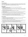
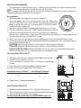
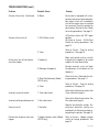
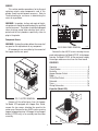
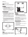
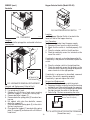
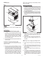
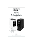
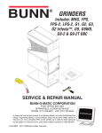
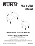
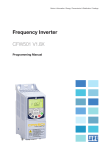
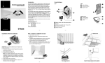
LPG
LPG-2E
OPERATING & SERVICE MANUAL
BUNN-O-MATIC CORPORATION
POST OFFICE BOX 3227
SPRINGFIELD, ILLINOIS 62708-3227
PHONE: (217) 529-6601 FAX: (217) 529-6644
To obtain the Illustrated Parts Catalog, visit the Bunn-O-Matic website, at www.bunn.com. This is absolutely FREE,
and the quickest way to obtain the catalog. Contact Bunn-O-Matic Corporation at 1-800-286-6070 to obtain a paper
copy of the required Illustrated Parts Catalog mailed via U.S. Postal Service.
27091.0000E 04/07 ©1996 Bunn-O-Matic Corporation
www.bunn.com
CONTENTS
User Notices..............................................................3
Electrical Requirements.............................................3
Operating Controls.....................................................3
Cleaning.....................................................................4
Coffee Grinding..........................................................4
Initial Set-Up..............................................................5
Adjustments...............................................................5
Troubleshooting.........................................................6
Service...................................................................... 8
Wiring Schematics...................................................18
INTRODUCTION
The LPG will store up to six pounds and the LPG-2E will store up to three pounds of whole bean coffee in each of two
hoppers and grind it to a preset grind and amount into an awaiting funnel and filter from most commercial drip coffee
brewers. The equipment is only for indoor use on a sturdy counter or shelf. Adequate space must be available above the
grinder to raise the lid when adding beans. Use only with whole bean coffee.
The grind is preset at the factory to drip specifications as set forth by the United States Department of Commerce and
adopted by the Coffee Brewing Center of the Pan American Coffee Bureau. Adjustments may be made to alter both the
amount and grind from the factory setting.
BUNN-O-MATIC COMMERCIAL PRODUCT WARRANTY
Bunn-O-Matic Corp. (“BUNN”) warrants equipment manufactured by it as follows:
1) All equipment other than as specified below: 2 years parts and 1 year labor.
2) Electronic circuit and/or control boards: parts and labor for 3 years.
3) Compressors on refrigeration equipment: 5 years parts and 1 year labor.
4) Grinding burrs on coffee grinding equipment to grind coffee to meet original factory screen sieve analysis: parts and labor for 3
years or 30,000 pounds of coffee, whichever comes first.
These warranty periods run from the date of installation BUNN warrants that the equipment manufactured by it will be commercially free
of defects in material and workmanship existing at the time of manufacture and appearing within the applicable warranty period. This
warranty does not apply to any equipment, component or part that was not manufactured by BUNN or that, in BUNN’s judgment, has
been affected by misuse, neglect, alteration, improper installation or operation, improper maintenance or repair, damage or casualty.
This warranty is conditioned on the Buyer 1) giving BUNN prompt notice of any claim to be made under this warranty by telephone
at (217) 529-6601 or by writing to Post Office Box 3227, Springfield, Illinois 62708-3227; 2) if requested by BUNN, shipping the
defective equipment prepaid to an authorized BUNN service location; and 3) receiving prior authorization from BUNN that the defective
equipment is under warranty.
THE FOREGOING WARRANTY IS EXCLUSIVE AND IS IN LIEU OF ANY OTHER WARRANTY, WRITTEN OR ORAL, EXPRESS OR IMPLIED,
INCLUDING, BUT NOT LIMITED TO, ANY IMPLIED WARRANTY OF EITHER MERCHANTABILITY OR FITNESS FOR A PARTICULAR
PURPOSE. The agents, dealers or employees of BUNN are not authorized to make modifications to this warranty or to make additional
warranties that are binding on BUNN. Accordingly, statements by such individuals, whether oral or written, do not constitute warranties
and should not be relied upon.
If BUNN determines in its sole discretion that the equipment does not conform to the warranty, BUNN, at its exclusive option while the
equipment is under warranty, shall either 1) provide at no charge replacement parts and/or labor (during the applicable parts and labor
warranty periods specified above) to repair the defective components, provided that this repair is done by a BUNN Authorized Service
Representative; or 2) shall replace the equipment or refund the purchase price for the equipment.
THE BUYER’S REMEDY AGAINST BUNN FOR THE BREACH OF ANY OBLIGATION ARISING OUT OF THE SALE OF THIS EQUIPMENT,
WHETHER DERIVED FROM WARRANTY OR OTHERWISE, SHALL BE LIMITED, AT BUNN’S SOLE OPTION AS SPECIFIED HEREIN,
TO REPAIR, REPLACEMENT OR REFUND.
In no event shall BUNN be liable for any other damage or loss, including, but not limited to, lost profits, lost sales, loss of use of
equipment, claims of Buyer’s customers, cost of capital, cost of down time, cost of substitute equipment, facilities or services, or any
other special, incidental or consequential damages.
27091 042007
USER NOTICES
Carefully read and follow all notices on the grinder and in this manual. They were written for your protection.
All notices on the grinder are to be kept in good condition. Replace any unreadable or damaged labels.
PERSONAL INJURY
HAZARD.
KEEP FINGERS AND
FOREIGN OBJECTS
OUT OF HOPPER
OR CHUTE OPENING.
#05876.0000
#37881.0000
#20545.0000
ELECTRICAL REQUIREMENTS
The grinder has an attached cordset and requires 2-wire, grounded service rated 120 volts ac, 15 amp, single
phase, 60 Hz for 120V models; 100 volts ac, 15 amp single phase, 50Hz for 100V models; and 230 volts ac, 10
amp single phase, 50 Hz for 230V models.
OPERATING CONTROLS
Off/On/Start Switch (Models LPG and LPG-2E)
OFF - (upper position) Switching to this position stops all operation of
the grinder.
ON - (middle position) The switch will return to this position after a
grind cycle has begun and will remain in this position after grinding has
ceased.
START - (lower, momentary position) Pressing the switch to this position
and releasing initiates a grind cycle.
P1028
Hopper Selector Switch (Model LPG-2E only)
LEFT - Switching to this position allows beans to be ground from the left
hopper.
RIGHT - Switching to this position allows beans to be ground from the
right hopper.
P1029
27091 042007
CLEANING
EXTERIOR SURFACES
The use of a damp cloth rinsed in any mild, nonabrasive, liquid detergent is recommended for cleaning all
surfaces on Bunn-O-Matic equipment. Care should be taken not to scratch the hopper or windows with any
abrasive material. Regular cleaning will keep your grinder looking new for years.
GRIND CHAMBER
1. WARNING - Unplug grinder before removal of any panel or grind chamber housing parts.
2. Empty all beans from both hopper(s).
3. Plug-in the grinder, place funnel with filter into funnel rails. Press the Off/On/Start switch to the “START”
lower position and release. Run a few grind cycles until all the coffee in the grind chamber is dispensed and
disconnect grinder from the power source.
4. Remove the funnel with filter and carefully tip the grinder over on it’s back.
5. Remove the two #10-32 screws securing burr housing cap assembly to the burr housing and remove burr
housing cap assembly.
6 Remove load disc and slide rotor with lower burr, spring and brass bushing off of the motor shaft.
7. Clean the grind chamber and all parts with a dry non metallic bristle brush and wipe with a dry clean cloth.
8. Reinstall brass bushing (flanged end first), spring and rotor with lower burr onto the motor shaft. Reinstall
load disc flat side toward rotor and burr housing cap assembly to the burr housing.
9. Refer to Initial Set-up/Adjustments section to vary grind or weight of dispensed coffee if necessary.
COFFEE GRINDING
1. On models LPG-2E, select (either left or right hopper) with selector switch and visually inspect the desired
hopper for an ample supply of whole bean coffee.
2. Place a paper filter into the brew funnel. The filter must not be folded-over or tilted to one side.
3. Insert the funnel into the funnel rails and push until it stops.
4. Momentarily press Off/On/Start switch to the “START” lower position and release. The grinding action will
stop automatically after the preset amount of ground coffee is dispensed into the funnel.
5. Remove the funnel from the grinder and level the bed of grounds by gently shaking.
6. The loaded funnel is now ready for use in any commercial drip coffee brewer according to the manufacturer’s
instructions.
STEP #1
STEP #2
STEP #3
STEP #4
STEP #5
27091 111598
INITIAL SET-UP/ADJUSTMENTS
The grind can be set from fine to very coarse. The grind may be adjusted for use in most commercial coffee
brewers. The following procedures should be used to make adjustments.
NOTE - A change in the burr adjustment will also change the amount dispensed. Any adjustment to the burrs
should be followed by an adjustment of the timer dials.
R SE - F
INE
A
Burr Adjustment
CO
1. Unplug the grinder and empty all beans from the hopper(s).
2. Plug-in the grinder, place funnel with filter into the funnel rails. Momentarily
press the Off/On/Start switch to the “START” (lower) position (with desired
hopper selected) and release, run a few grind cycles until all of the coffee in
the grind chamber is dispensed.
3. Remove the funnel with filter and carefully tip the grinder over on it’s back.
B U NN
4. Place the Off/On/Start switch in the “START” (lower) position and, using the
grind adjustment key provided, slowly turn the adjusting screw in a clockwise
P1073
direction until a metallic whine is heard due to the rubbing of the grinding burrs. (It may be necessary to
start more than one grind cycle to obtain the sound).
5. Make a mark with a pen on the decal to note the position of the arrow on the grind adjustment screw.
6. The following settings approximately correspond to the CBC recognized grinds. All are referenced from the
arrow position marked in step #5.
FINE GRIND: Rotate the adjusting screw 7 hash marks in a counterclockwise direction.
DRIP GRIND: Rotate the adjusting screw 8 hash marks in a counterclockwise direction.
REGULAR (COARSE) GRIND: Rotate the adjusting screw 10 hash marks in a counterclockwise direction.
NOTE: Exact adjustment will vary according to bean roast or added flavoring.
Timer Adjustment (Model LPG-2E)
1. Fill hoppers with whole bean coffee and select hopper to be adjusted.
2. Remove the cover frpm the timer dials.
3. Set the timer dial to 2 seconds for each 1-1/2 ounces of ground coffee
desired.
4. Grind a few cycles to verify the setting by weighing samples.
5. Adjust the timer to correspond with the chart below.
Approximate Amount (in Ounces)
1-1/2
2-1/4
3
Timer Settings (in Seconds)
2
3
4
P1035
6. Repeat steps 2 - 4 for remaining hopper.
Timer Adjustment (Model LPG)
1. Unplug the grinder and remove the 2” hole plug in the rear cover.
2. Set the timer dial to 5 seconds for each ounce of ground coffee desired.
3. Verify the setting by weighing a few samples.
Use this 5 second per ounce figure as an APPROXIMATE guide only.
P1744
27091 111598
TROUBLESHOOTING
A troubleshooting guide is provided to suggest probable causes and remedies for the most likely problems
encountered. If the problem remains after exhausting the troubleshooting steps, contact the Bunn-O-Matic
Technical Service Department.
• Inspection, testing, and repair of electrical equipment should be performed only by qualified service personnel.
• All electronic components have ac voltage and dc voltage potential on their terminals. Shorting of terminals or the application of external voltages may result in board failure.
• Intermittent operation of electronic circuit boards is unlikely. Board failure will normally be permanent. If an intermittent condition is encountered, the cause will likely be a switch contact or a loose connection at a terminal or crimp.
• Make certain that all electrical connections are tight and isolated.
WARNING
• Exercise extreme caution when servicing electrical equipment.
• Turn power OFF when servicing, except when electrical tests are specified.
• Follow recommended service procedures.
• Replace all protective shields or safety notices.
Problem
Probable Cause
Remedy
Grinder will not start.
1. No power or incorrect voltage
(A) Plug-in the grinder.
(B) Check the voltage at the wall
outlet with a voltmeter. It must be
120 volts ac for 120 volt models,
100 volts for 100 volt models, and
230 volts for 230 volt models.
2. Off/On/Start switch
(A) Momentarily press the Off/On/
Start switch to the “START”(lower)
position.
(B) Refer to Service - Off/On/Start
switch for testing procedures. See
page 14
3. Circuit Breaker (Not applicable on Press the “Reset” button, located on
Model LPG with capacitor)
rear of the grinder. Listen carefully
for a “click”. This resets the motor
protection circuit and indicates that
an overload may have been encountered by the motor. (An overload can
occur when something other than
coffee is inserted into the hopper for
grinding). Refer to Service - Circuit
Breaker for testing procedure. See
page 9
4. Timer
Refer to Service - Timer for testing
procedures. See page 16
27091 111598
TROUBLESHOOTING (cont.)
Problem
Probable Cause
Grinder will not start. (Continued)
5. Motor
Grinder will not shut off.
1. Off/On/Start switch
Remedy
Each motor is equipped with a temperature and current overload protection feature which will immediately
shut off the motor when an overload
has occurred. Check the grinder for
obstructions. Refer to Service - Motor
for testing procedures. See page 11
Refer to Service - Timer for testing
procedures. See page 16
2. Timer
Grinder starts, but will not dispense
from either hopper.
1. Hopper(s)
Begin each grind cycle by visually
inspecting the hopper(s) for ample
supplies of whole bean coffee.
2. Blockage of hopper(s)
Foreign materials must not block
the openings at the bottom of the
hopper(s).
3. Slide Gate Solenoids (Model
LPG-2E only)
Incorrect amount of coffee.
Incorrect coffee grind dispensed.
A) Place the switch in the “OFF” upper
position.
(B) Refer to Service - Off/On/Start
Switch for testing procedures. See
page 14
Refer to Service - Solenoids for testing procedures. See page 14
4. Timer
Refer to Service - Timer for testing
procedures. See page 16
1. Timer adjustment
Refer to the Adjustments section. See
Timer adjustment page 5.
1. Burr adjustment
Refer to the Adjustment section. See
Burr adjustment page 5.
Replace the dechaffer springs. Replacement dechaffer springs are
provided in the literature package accompnting the grinder. See page 10
Excessive chaff
1. Dechaffer
Grinder only dispenses from one
hopper
1. Hopper selector switch (Model
LPG-2E only)
Refer to Service - Hopper selector
switch for testing procedures. See
page 10
27091 111598
SERVICE
This section provides procedures for testing and
replacing various major components used in this
grinder should service become necessary. Refer to
Troubleshooting for assistance in determining the
cause of any problem.
WARNING - Inspection, testing, and repair of electrical equipment should be performed only by qualified
service personnel. The grinder should be unplugged
when servicing, except when electrical tests are required and the test procedure specifically states to
plug-in the grinder.
SCHEMATIC WIRING DIAGRAM
LPG-2E, LPGB-2E
L1
N
GRN
BLK
SELECTOR
SWITCH
3
AMP
WHI
GRN
TIMER ASSY.
(Hopper Slide
Gate Timer
Dial Wiring)
Right - Brown
Left - Orange
1
2
3
4
5
6
7
8
9
10
OFF/ON/START
SWITCH
WHI
BLU
YEL
WHI/BLK
BLK
RED
VIO
ORA
BLK GRINDER
WHI
RED
M
RED
RED
RT
SOL
RED
RED
SLIDE GATES
RED
LT
SOL
RED
RED
YEL
WHI
100 VOLTS AC
120 VOLTS AC
2 WIRE
SINGLE PHASE
60 HZ
27103.0000D 04/07 ©1996
BUNN-O-MATIC CORPORATION
Component Access
WARNING - Unplug the grinder before the removal of
any panel or the replacement of any component.
All components are accessible by the removal of
the hopper and the rear panel.
FIG.2 REAR PANEL REMOVAL
P1034
Remove the four #8-32 screws securing the rear
panel and knob cover for Model LPG-2E, to the hopper
housing. On Model LPG-2E, let the rear panel hang by
the orange and brown wires from the timer board.
CONTENTS
Capacitor.................................................................. 9
Circuit Breaker......................................................... 9
Dechaffer............................................................... 10
Hopper Selector Switch......................................... 10
Motor..................................................................... 11
Off/On/Start Switch................................................ 14
Solenoids............................................................... 14
Timer..................................................................... 16
Wiring Schematics................................................. 18
Capacitor (Model LPG)
FIG. 1 HOPPER REMOVAL
P1033
Remove all the coffee beans from the hopper.
On Model LPG equipped with Hopper Burr Guard,
remove the two screws attaching the guard to the
motor cover. Remove the four #8-32 screws securing
hopper to hopper housing. Lift hopper, lid and hopper
divider (LPG-2E only) as an assembly over the motor
assembly.
F/ST
OF
el
1.
2.
3.
into
OP
.
rails
n.
sitio
po
funn
ide
RT"
d sl
TA
an
d.
"S
el
to
ishe
funn
itch
n fin
to
sw
r in
whe
the
filte
sh
stop
ce
y pu
ally
Pla
taril
atic
en
tom
Mom
ill au
w
r
de
Grin
T
AR
ST
FIG. 3 CAPACITOR
P1745
27091 111598
SERVICE (cont.)
Capacitor (Model LPG)(cont.)
Location:
The capacitor is located inside the front panel of
the hopper housing next to the Off/On/Start switch.
Test Procedure:
1. Disconnect grinder from the power source.
2. Visually inspect the capacitor for leakage. If leakage
is visible, replace the capacitor.
3. Connect the grinder to the power source, if the
motor does not run, disconnect the capacitor
wiring harness from the main wiring harness. If
the motor now runs, replace the capacitor.
Removal and Replacement:
1. Disconnect the capacitor wiring harness from the
main wiring harness.
2. Remove the #8-32 nut attaching the capacitor
and mounting bracket to the hopper housing and
remove the bracket, shield, capacitor and capacitor
wiring harnes as an assembly.
3. Disconnect the wiring harness from the capacitor
and attach it to a new capacitor making sure the
black wire attaches to the positive (+) pole, FIG.
4.
4. Wrap the shield around the capacitor and place
into the mounting bracket. Slide the lower tab of
the mounting bracket between the wrapper and
base and secure in place over the mounting stud
with the #8-32 nut.
5. Reconnect the wiring harness to the main wiring
harness.
+
BLK
P1036
FIG. 5 CIRCUIT BREAKER
Test Procedure:
1. Disconnect grinder from the power source.
2. Remove the wires from the circuit breaker.
3. Check for continuity between the terminals. Continuity must be present between the terminals.
If continuity is present as described the circuit breaker
is functioning properly.
If continuity is not present as described, press reset
button and repeat step #3, if continuity is not present
as described, replace the circuit breaker.
Removal and Replacement:
1. Remove the wires from the circuit breaker.
2. Remove the face nut securing circuit breaker to
the motor support.
3. Remove circuit breaker.
4. Install new circuit breaker in motor support and
secure with face nut.
5. Reconnect the wires.
6. Refer to FIG. 6 when reconnecting the wires.
WHI/BRN
RED from Motor-LPG-2E
BLK from Start Switch-LPG
P1747
FIG. 4 CAPACITOR TERMINALS
Circuit Breaker
Location:
The circuit breaker is located on the rear of the
grinder next to the power cord strain relief bushing.
The circuit breaker is not available on Model LPG
equipped with capacitor.
BLK from Power Cord
FIG. 6 CIRCUIT BREAKER TERMINALS
P1037
27091 111598
SERVICE (cont.)
Hopper Selector Switch (Model LPG-2E)
Dechaffer
FIG. 9 HOPPER SELECTOR SWITCH
Location:
The Hopper Selector Switch is located in the
lower left front of the hopper housing.
P1062
FIG. 7 DECHAFFER
P1029
Location:
The dechaffer spring plates are located in the burr
housing cap.
Test Procedure:
1. Disconnect grinder from the power supply.
2. Remove all wires from the switch terminals.
3. Check that the switch is installed properly, FIG.
10.
4. Place the selector switch in the left position.
5. Check for continuity across the terminals on the
rear of the switch.
2
1
If continuity is present as described proceed to #6.
If continuity is not present as described, replace the
switch.
6. Place the selector switch in the right position.
7. Check for continuity across the terminals on the
rear of the switch. Continuity should not be present
across terminals in the right position.
3 2 1
If continuity is not present as described, reconnect
the wires, the switch is operating properly.
If continuity is present replace the switch.
OPTONAL EXTRA
FINE DECHAFFER
Removal and Replacement:
1. Remove all wires from the switch terminals.
2. Compress the clips inside the front of the housing
and gently push the switch through the opening.
3. Push the new switch into the opening and spread
the clips to retain the switch in the housing.
4. Refer to Fig. 10 when reconnecting the wires.
P1063
FIG. 8 DECHAFFER REMOVAL/REPLACEMENT
Removal and Replacement: Refer to Fig. 8
1. Remove coffee beans from hopper(s).
2. Lay grinder on it’s back.
3. Remove the #4-40 truss head screw securing
dechaffer support (1) to the burr housing cap.
4. Remove dechaffer support (1).
5. Remove dechaffer spring plate (2) from burr hosing cap.
6. For models with extra fine dechaffer, remove
dechaffer support (3).
7 Place new dechaffer spring plate (2) in the slot in
the burr housing cap.
8. Place dechaffer support (1) over dechaffer spring
plate (2), support (3) and secure with a #4-40 truss
head screw.
WHI to OFF/ON/START Switch
BLU to Timer P1-4 (blu)
P1038
10
FIG. 10 HOPPER SELECTOR SWITCH TERMINALS
(Viewed from rear)
27091 061400
NOTE: Clean all grind burrs and mounting surfaces
before reassembly.
SERVICE (cont.)
Motor
Removal and Replacement:
1. On Model LPG-2E, disconnect the black wire and
the white wire to the motor from the main wiring
harness, the red wire to the circuit breaker and
the red wire to the Off/On/Start switch. On Model
LPG disconnect the motor wiring harness from
the main wiring harness.
2. On Model LPG-2E, disconnect the red wire from
the left and right solenoid, the orange wire from
the left solenoid and the violet wire from the right
solenoid.
2
FIG. 11 MOTOR
3
P1022
Location:
The motor is located inside the hopper assembly.
1
Test Procedures:
1. Disconnect grinder from the power supply.
2. On Model LPG-2E, disconnect the black wire and
the white wire to the motor from the main wiring
harness, the red wire to the circuit breaker and
the red wire to the Off/On/Start switch. On Model
LPG disconnect the motor wiring harness from
the main wiring harness.
3. Connect the leads of an ohm meter to the red wires
from the motor.
P1049
FIG. 12 MOTOR REMOVAL
3. Refer to Fig 12. Remove the three #10-32 x .25”
screws (1) securing the motor to the motor support bracket.
4. Remove the motor, solenoid and solenoid components (2) from the hopper housing (3) as an
assembly.
NOTE: Steps 5 thru 14 apply only to Model LPG-2E.
If continuity is present the overload is good.
If continuity is not present the overload will not reset,
replace the motor.
4. Set an ohm meter to read at least 20 ohms. Connect
the leads from the ohm meter to the black wire and
the white from the motor. The ohm reading should
be approximately 18 ohms. Using the bean agitator
slowly rotate the motor shaft in approximately 1/8
turn steps through one full rotation. If ohm readings are consistent motor windings are good. If
readings vary more than ±1 ohm, replace motor.
11
5. Refer to Fig.13. Remove the three #8-32 Keps
nuts.
6. Lift the retaining ring w/hopper gasket (1) over the
motor and burr housing assembly (9). Set aside
for reassembly.
7. Remove the filler plate (2) and set aside for reassembly.
8. Lift slide plate, solenoid plunger and spring (3) off
of the dowel pin in the mounting ring (6) and slide
solenoid plunger and spring (3) out of solenoid
coil. Set aside for reassembly. Repeat for opposite
side.
27091 111598
SERVICE (cont.)
1
Motor (cont.)
9. Slide spacer plate (4) off of burr housing divider
(8) and set aside for reassembly.
10.Loosen the #10-32 setscrew (5) securing the
mounting ring and solenoid bracket (6) to the burr
housing.
11.Lift mounting ring, solenoid bracket and solenoids
(6) over the motor and burr housing assembly (9)
and set aside for reassembly.
12.Remove the #8-32 setscrew (7) and set aside for
reassembly.
13. Lay motor on it’s side.
2
3
4
6
3
NOTE: Refer to Fig. 14 for the disassembly and assembly of the burrs and rotor.
5
14. Remove the two #10-32 fillister head screw securing
burr housing cap (10) to the burr housing.
15.Remove cap, burr adjusting screw, decaffing plate
and decaffer support (10) as an assembly. Set
aside for reassembly.
16.Remove load disc (11) and set aside for reassembly.
17.Slide rotor (12), lower burr (13) and spring (14)
as an assembly off the motor shaft, set aside for
reassembly.
18. Remove burr housing divider (8) and set aside
for reassembly.
7
9
8
NOTE: Inspect rotor. If rotor needs to be replaced,
remove the two #10-32 binding head screws securing lower burr (13) to the rotor and remove burr.
Install lower burr (13) on new rotor (12) using two
#10-32 binding head screws.
FIG. 13 SOLENOID AND GATES
P1050
1.
2.
3.
4.
5.
6
Retaining Ring W/Hopper Gasket
Filler Plate
Slide Plate, Solenoid Plunger and Spring
Spacer Plate
Setscrew, #10 -32
Mounting Ring, Solenoid and Solenoid Mounting
Plate
7. Setscrew, #8-32
8. Burr Housing Divider
9. Motor and Burr Housing
19.Slide spring retaining bushing (15) off the motor
shaft and set aside for reassembly.
20.Remove the two #10-32 binding head screws
securing the upper burr (16) to the motor and
housing assembly (17).
21.Remove the upper burr (16) and set aside for
reassembly.
NOTE: If burrs need to be replaced, they must be
replaced in matched pairs.
12
27091 111598
SERVICE (cont.)
Motor (cont.)
13
MODEL LPG ONLY
10 11
12
13 14 15 16
17
18
FIG. 14 ROTOR/AUGER, BURRS AND MOTOR COVER
P1051
32.Install solenoids, solenoid bracket and mounting
ring (6) as an assembly on the new motor with the
solenoids located to the opposite side of the burr
housing divider (8).
33.Install spacer plate (4) on burr housing divider (8)
making sure the hole in the spacer plate (4) lines
up with the hole in the mounting ring (6).
34.Install solenoid plunger with spring and slide plate
(3) as an assembly into the solenoid coil. Place slide
plate on the dowel in the mounting ring. Repeat for
the opposite side.
35.Place filler plate (2) on mounting ring (6) over the
top of the slide plates (3) with the holes in the filler
plate in line with the holes in the mounting ring.
36.Install retaining ring w/hopper gasket (1) using
three #8-32 pan head screws and three #8-32 keps
nuts.
37.Refer to Fig.12. Install motor, solenoids and solenoid
components (2) in the hopper housing (3) using
three #10-32 truss head screws (1).
38.Reconnect wires for motor and solenoids. Refer to
wiring schematic on page 18.
22.Remove the two #8-32 flat head screws securing
the motor cover (18) to the motor and housing
assembly (17) and remove the cover. Set aside for
reassembly.
23.Discard old motor and housing assembly.
24. Place new motor on it’s side and install motor cover
(18) using two #8-32 flat head screws.
25.Install upper burr (16) to the new motor and housing assembly (17) using two #10-32 binding head
screws.
26.Install spring retaining bushing (15) on motor
shaft.
27.Refer to Fig. 13. Install burr housing divider (8) in
slot in the burr housing and secure with #8-32 cup
point setscrew (7), for Model LPG-2E only.
28.Refer to Fig. 14. Install rotor (12), lower burr (13) and
spring (14) as an assembly on the motor shaft.
29. Install load disc (11) flat side towards rotor.
30.Install burr housing cap (10), adjusting screw,
dechaffing spring plate and dechaffer support as an
assembly to the new motor and housing assembly
(17) using two #10-32 fillister head screws.
31.Set motor upright with burr housing at the bottom.
NOTE: Steps 32 thru 36 apply only to Model LPG-2E.
13
27091 111598
Removal and Replacement:
1. Remove all wires from the switch terminals.
2. Compress the clips inside the front of the hopper
housing and gently push the switch through the
opening.
3. Push the new switch into the opening and spread
the clips to retain the switch in the hopper housing.
4. Reconnect all the wires to the switch terminals.
5. Refer to Fig. 16 when reconnecting the wires.
SERVICE (cont.)
OFF/ON/START Switch
YEL to Timer P1-5 - LPG-2E
WHI/BRN to Timer P1-5 - LPG
RED from Motor
WHI from Power Cord to Hopper
Selector Switch - LPG-2E
WHI/BLU to Timer P1-4 - LPG
RED to Left and Right
Solenoid - LPG-2E
BLK to Power
Cord - LPG
P1057
FIG. 15 OFF/ON/START SWITCH
FIG. 16 OFF/ON/START SWITCH TERMINALS
(Viewed from rear)
P1028
Location:
The Off/On/Start switch is located on the right front
side of the hopper housing.
Solenoid (Model LPG-2E)
Test Procedure:
1. Disconnect grinder from the power source.
2. Remove all wires from the switch terminals.
3. Check for continuity across the .187” terminals of
the switch when it is held in the lower “START”
position. Continuity must not be present across
these terminals in the center or upper position.
If continuity is present as described, proceed to #4.
If continuity is not present as described, replace the
switch.
FIG. 17 SOLENOIDS
4. Check for continuity across the .25” terminals of the
switch when it is in the “ON” position. Continuity
must not be present in the upper “OFF” position.
P1058
Location:
The solenoids are located inside the hopper housing behind the left and right side of the motor.
If continuity is present as described, reconnect the
wires, the switch is operating properly.
If continuity is not present as described, replace the
switch.
Test Procedure:
1. Disconnect grinder from the power source.
2. Remove both wires from the solenoid coil terminals.
3. Check the voltage across the red wire and the violet
wire removed from the right solenoid or the red
wire and the orange wire removed from the left
14
27091 111598
SERVICE (cont.)
3
Solenoid (cont.)
4
5
solenoid with a voltmeter. Connect the grinder to
the power source and place the Off/On/Start switch
in the “ON” center position. The indication must
be 120 volts AC.
4. Disconnect the grinder from the power source.
If voltage is present as described, proceed to #5.
If voltage is not present as described, refer to the wiring
diagram and check grinder wiring harness.
5. Check for continuity across the solenoid coil terminals.
1
6
2
P1059
FIG. 18 SOLENOID REMOVAL AND INSTALLATION
If continuity is present as described, reconnect the
violet wire and the red wire on the right solenoid or the
orange wire and the red wire on the left solenoid.
If continuity is not present as described, replace the
solenoid.
6. Install new solenoid (4) on mounting bracket (3)
using four #8-32 truss head screws.
7. Slide new solenoid (4) and mounting bracket (3)
on the solenoid plunger (5) far enough so the hole
in the mounting bracket (3) is in line with the hole
in the solenoid mounting plate (6).
8. Install shoulder screw (2).
9. Slide timer mounting bracket and timer (1) under
the two #8-32 pan head screws on the left rear of
the motor support and tighten screws.
10.Repeat steps #3 through #8 for the right solenoid.
11.Refer to Fig. 19 and reconnect the wires to the
solenoid coil terminals.
6. Check the solenoid for coil action when the Off/
On/Start switch is momentarily pressed to the
“START” (lower) position and released. Connect
grinder to the power source. Watch the slide gate
open and close as the coil magnet attracts and
after a period of time, releases the plunger.
7. Disconnect the grinder from the power source.
If the slide gate functions as described the solenoid
is operating correctly.
If the slide gate does not function as described, replace
the solenoid.
Removal and Replacement: Refer to Fig. 18
1. Loosen the two #8-32 pan head screws securing
the timer mounting bracket to motor support.
2. Move timer bracket, timer and rear cover (1) away
from the rear of the left solenoid.
3. Remove the shoulder screw (2) securing the
solenoid to the solenoid mounting plate (6). Set
aside for reassembly.
4. Slide solenoid (4) and solenoid mounting bracket
(3) off of the solenoid plunger (5).
5. Remove the four #8-32 truss head screw securing
the solenoid (4) to the solenoid mounting bracket
(3). Set mounting bracket (3) and the four screws
aside for reassembly.
FIG. 19 SOLENOID COIL TERMINALS
15
P1060
27091 111598
SERVICE (cont.)
7. Place the hopper selector switch in the right position.
8. Insert the leads of a voltmeter set to read at least 120
volts AC, along side the red wire (terminal 8) and the
violet wire (terminal 9) of the harness plug. Place the
Off/On/Start switch in the “START” lower position. Connect the grinder to the power source. The indication
must be 120 volts AC for the set gate time and return
to 0 volts.
9. Disconnect the grinder from the power source.
Timer (Model LPG-2E)
If voltage is present as described, proceed to step#10.
If voltage is not present as described, replace the timer.
FIG. 20 TIMER
10. Insert the positive (+) lead of a volt meter set to read at
least 120 volts DC, along side the black wire (terminal
7) of the harness plug and insert the negative (-) lead
along side the white/black wire (terminal 6) of the harness plug. Place the Off/On/Start switch in the “START”
lower position. Connect the grinder to the power source.
The indication must be 120 volts DC for the set gate
time plus clean out time and return to 0 volts.
P1061
Location:
The timer is located inside the hopper housing just
behind the left solenoid.
If voltage is present as described the timer is operating
properly.
If Voltage is not present as described, replace the timer.
Test Procedure:
1. Disconnect grinder from the power source.
2. Insert the leads of a voltmeter set to read at least 120
volts AC, along side the red wire (terminal 8) and the
white wire (terminal 2) of the harness plug. Place the
Off/On/Start switch in the “ON” center position. Connect
the grinder to the power source. The indication must be
120 volts AC.
3. Disconnect the grinder from the power source.
Removal and Replacement:
1. Disconnect the main wiring harness plug from the
terminal block on the timer.
2. Remove the two timer dial knobs located on the rear
panel of the grinder.
3. Remove nut and internal tooth lockwasher securing
dials to the rear panel.
4. Loosen the two #8-32 pan head screws securing the
timer and timer mounting bracket to the motor support
plate.
5. Remove timer and timer mounting bracket from the
grinder.
6. Remove the four #6-32 keps nuts securing the timer
to the mounting bracket. Leave the four spacers on the
mounting bracket studs.
7. Place new timer over the studs on the mounting bracket
and secure with four #6-32 keps nuts.
If voltage is present as described, proceed to step #4.
If voltage is not present as described, refer to the wiring
diagram and check the grinder wiring harness.
4. Place the hopper selector switch in the left position.
5. Insert the leads of a voltmeter set to read at least 120
volts AC, along side the red wire (terminal 8) and the
orange wire (terminal 10) of the harness plug. Place
the Off/On/Start switch in the “START” lower position.
Connect the grinder to the power source. The indication
must be 120 volts AC for the set gate time and return
to 0 volts.
6. Disconnect the grinder from the power source.
If voltage is present as described, proceed to step #7.
If voltage is not present as described, replace the timer.
16
27091 111598
SERVICE (cont.)
Timer (Model LPG-2E)
3. Disconnect the grinder from the power source.
8. Slip timer and timer mounting bracket under the
two screws on the motor support plate and tighten
screws.
9. Locate the left and right timer dials in their proper
place on the rear panel and secure with nuts and
internal tooth lockwashers.
10.Place timer knobs on timers.
11.Reconnect harness plug to the terminal block on
the timer board.
If voltage is present as described, proceed to step
#4.
If voltage is not present as described, refer to the wiring
diagram and check the grinder wiring harness.
4. Insert the positive (+) lead of a volt meter set to
read at least 120 volts DC (157 volts DC on units
with capacitor), along side the black wire (terminal
3) of the harness plug and insert the negative (-)
lead along side the white wire (terminal 6) of the
harness plug. Place the Off/On/Start switch in the
“START” lower position. Connect the grinder to the
power source. The indication must be 120 volts DC
for 120 volt models (157 volts DC on units with
capacitor), 100 volts for 100 volt models, and 230
volts for 230 volt models for the set time and return
to 0 volts.
5. Disconnect the grinder from the power source.
Timer (Model LPG)
If voltage is present as described the timer is operating
properly.
If Voltage is not present as described, replace the
timer.
FIG. 21 TIMER
P1748
Location:
The timer is located inside the rear access panel.
Adjustments can be made by removing the 2” hole
plug.
Test Procedure:
1. Disconnect grinder from the power source.
2. Insert the leads of a voltmeter set to read at least
120 volts AC, along side the red wire (terminal 1)
and the white/black wire (terminal 2) of the harness
plug. Place the Off/On/Start switch in the “ON”
center position. Connect the grinder to the power
source. The indication must be 120 volts AC for
120 volt models, 100 volts for 100 volt models,
and 230 volts for 230 volt models.
17
27091 111598
WIRING SCHEMATICS
SCHEMATIC WIRING DIAGRAM
LPG-2E, LPGB-2E
L1
N
GRN
BLK
SELECTOR
SWITCH
3
AMP
WHI
GRN
TIMER ASSY.
(Hopper Slide
Gate Timer
Dial Wiring)
Right - Brown
Left - Orange
1
2
3
4
5
6
7
8
9
10
OFF/ON/START
SWITCH
WHI
BLU
YEL
WHI/BLK
BLK
RED
VIO
ORA
BLK GRINDER
WHI
RED
M
RED
RED
RT
SOL
SLIDE GATES
RED
RED
RED
LT
SOL
RED
RED
YEL
WHI
100 VOLTS AC
120 VOLTS AC
2 WIRE
SINGLE PHASE
60 HZ
27103.0000D 04/07 ©1996
BUNN-O-MATIC CORPORATION
18
27091 042007
WIRING SCHEMATICS
19
27091 042007
WIRING SCHEMATICS
SCHEMATIC WIRING DIAGRAM
LPG & LPG2
L1
B
L
K
GREEN
3
AMP
TIMER
BLK
RED
WHI/BLK
BLK
WHI/BLU
WHI/BRN
WHI
GRN
BLK
RED
WHI/BRN
WHI/BLU
DC
MOTOR
BLK
WHI
RED
RED
120 VOLTS AC
2 WIRE
SINGLE PHASE
60 HZ
P1
1
2
3
4
5
6
P2
1
2
3
4
5
P3
1
2
3
4
N
W
H
I
RED
WHI/BLK
BLK
WHI/BLU
WHI/BRN
WHI
BLK
RED
WHI/BRN
WHI/BLU
BLK
WHI
RED
RED
10529.0000C 3/92 © 1990
BUNN-O-MATIC CORPORATION
20
27091 111598
WIRING SCHEMATICS
SCHEMATIC WIRING DIAGRAM
LPG-A
L1
B
L
K
GRN/YEL
3
AMP
TIMER
BLK
RED
WHI/BLK
BLK
WHI/BLU
WHI/BRN
WHI
GRN
BLK
RED
WHI/BRN
WHI/BLU
DC
MOTOR
BLK
WHI
RED
RED
230 VOLTS AC
2 WIRE
SINGLE PHASE
50/60 HZ
P1
1
2
3
4
5
6
P2
1
2
3
4
5
P3
1
2
3
4
L2
R
E
D
RED
WHI/BLK
BLK
WHI/BLU
WHI/BRN
WHI
BLK
RED
WHI/BRN
WHI/BLU
BLK
WHI
RED
RED
10529.0002E 8/01 © 1990
BUNN-O-MATIC CORPORATION
21
27091 082701
WIRING SCHEMATICS
SCHEMATIC WIRING DIAGRAM
LPG W/Capacitor
L1
N
GREEN
BLK
TIMER
BLK
RED
WHI/BLK
BLK
WHI/BLU
WHI/BRN
WHI
GRN
BLK
BLK
+
WHI/BRN
_
BLK
RED
WHI/BRN
WHI/BLU
DC
MOTOR
W
H
I
BLK
WHI
RED
RED
P1
1
2
3
4
5
6
RED
WHI/BLK
BLK
WHI/BLU
WHI/BRN
WHI
P4
2
1
BLK
WHI/BRN
P2
1
2
3
4
5
P3
1
2
3
4
BLK
RED
WHI/BRN
WHI/BLU
BLK
WHI
RED
RED
120 VOLTS AC 2 WIRE
SINGLE PHASE 60 HZ
10529.0003E 10/98 © 1998
BUNN-O-MATIC CORPORATION
22
27091 111598
WIRING SCHEMATICS
SCHEMATIC WIRING DIAGRAM
LPG-B
L1
B
L
K
GREEN
3
AMP
TIMER
BLK
RED
WHI/BLK
BLK
WHI/BLU
WHI/BRN
WHI
GRN
BLK
RED
WHI/BRN
WHI/BLU
DC
MOTOR
BLK
WHI
RED
RED
100 VOLTS AC
2 WIRE
SINGLE PHASE
50-60 HZ
P1
1
2
3
4
5
6
P2
1
2
3
4
5
P3
1
2
3
4
N
W
H
I
RED
WHI/BLK
BLK
WHI/BLU
WHI/BRN
WHI
BLK
RED
WHI/BRN
WHI/BLU
BLK
WHI
RED
RED
10529.0001D 10/98 © 1990
BUNN-O-MATIC CORPORATION
23
27091 111598