1
A. Servicing the Model 35 / 45
manifold o-rings are worked hard and are more prone to failure than
some of the other seals inside the watermaker.
Step 9: Remove collar
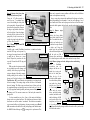
from pump body
Using
the
1/2"
wrench, remove the
remaining four hex
nuts and their flat
washers from the
threaded rods protruding from the drive
end of the pump body.
When they have been
removed, slide the
rectangular
metal
gland
plate
off
the
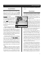
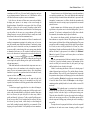
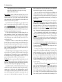
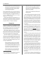
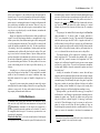
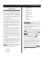
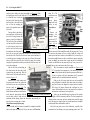
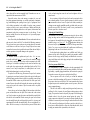
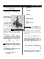
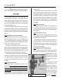
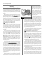
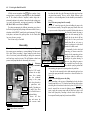
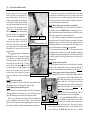
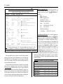
Figure A-8: Collar, Gland Plate and Pump Body
threaded rods.
Unless there is significant corrosion around the threaded rods and
gland plate, the latter should be relatively easy to remove. If necessary,
use a flat-bladed screwdriver to gently pry the gland plate up and get it
started. Be careful not to exert too much pressure with the screwdriver on
the plastic pump back.
When doing this, be aware that the gland plate will only slide off the
threaded rods easily if it remains perpendicular to them. If you pry up on
only one side of the gland plate, it will cause it to bind against the rods
and become difficult to remove. Therefore, if a little prying is necessary,
work your way around the gland plate, using the screwdriver to lift it just
a short distance on each of its four sides in turn.
After removing the hex nuts, washers and gland plate, pull the pump
collar away from the pump body. It should be easy to remove. The pump
back and front should remain together at this point. Remove any corrosion on the gland plate and threaded rods with the wire brush, wipe the
plastic collar clean with a rag, and set them aside. See Figure A-8.
Step 10: Separate the pump front and pump back
At this stage of the disassembly process, the pump front and back are
held together only by the compression of the o-rings on each end of the
cylinder. One end of the cylinder is seated in a circular cavity in the
pump front and the other end is seated in a similar cavity in the pump
back.
The
instructions direct the
user to use a flat-bladed screwdriver
to pry the two pump halves apart.
Before resorting to such a heavyhanded technique, try separating
them by grasping the pump front in
one hand, the pump back in the
other, and pulling them apart with
firm pressure. While trying to pull
them apart, exert a little back-andforth sideways force on the pump
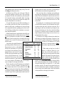
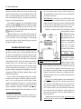
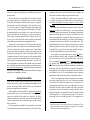
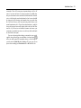
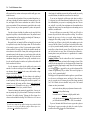
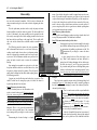
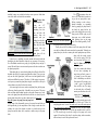
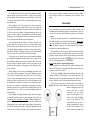
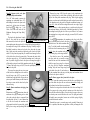
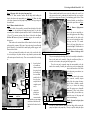
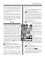
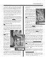
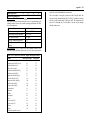
Figure A-9: Pump Front and Back Separated
front. This should gradually “walk”
the cylinder and its o-rings out of the cavity.
Usually the end of the cylinder seated in the pump front will come
out, and the cylinder will remain seated in the pump back. When the two
pump halves part, the valve retainer plate in the pump front may fall out,
along with the intake poppet
valve and its spring. Take care
not to lose them. See Figure A-9.
Step 11: Remove check valves
from pump front
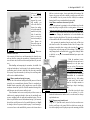
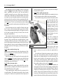
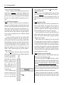
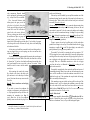
If the valve retainer plate did not
fall out when separating the
pump front and back, remove it
by “pouring” it out of the pump
front. It should drop out with no
effort required. If necessary, grip
it with a pair of needle-nosed
pliers and lift it out. The spring
for the intake valve will usually
remain press-fitted into the valve
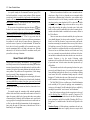
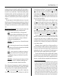
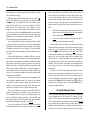
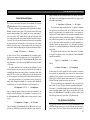
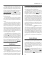
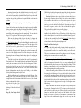
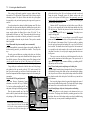
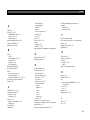
retainer plate. See Figure A-10.
With the valve retainer plate
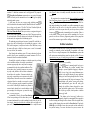
Figure A-10: Intake & Discharge Valve Assemblies
removed, the intake poppet valve
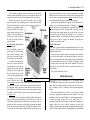
can be lifted out if it hasn’t already dropped out of its seat. The intake valve seat will remain pressed
into its cavity in the pump front. Examine the valve seat with a magnifying glass. Note that there is a beveled edge around the hole in its center. This beveled edge is what the o-ring on the poppet valve seats
against. If the surface of the bevel is in perfect shape, with no scratches,
nicks or dents, it can be left in place and reused.