1
Vídeňská 172, Vestec
252 42 Jesenice u Prahy
Česká republika
Tel: +420-234 144 746, 790
Fax: +420-234 144 710, 777
Rotary Arm
Product Specification
Service Instructions
Maintenance
Pragometal s.r.o.
WRA TS
Rotation wrapping machine can only be operated by an employee who has
been assign to it and has been acquainted with these instructions and
safety rules herein stated in a demonstrable way.
TABLE OF CONTENT
1.
GENERAL .................................................................................4
2.
SAFETY INSTRUCTIONS.......................................................10
3.
ACTIVATION AND HANDLING ..............................................14
4.
TECHNICAL PARAMETERS ..................................................17
5.
EQUIPMENT ...........................................................................19
6.
OPERATING STAFF ...............................................................29
7.
FAULTS AND THEIR REMOVALS.........................................75
8.
MACHINE MAINTENANCE AND CLEANING ........................86
9.
WARRANTY.............. CHYBA! ZÁLOŽKA NENÍ DEFINOVÁNA.
10.
SERVICING ........................................................................104
3
Pragometal s.r.o.
WRA TS
1. GENERAL
These instructions are the original instructions for use according to Directive EU
no. 2006/42/ES and they are authorized by the manufacturer.
1.1. Utilization
Rotary Arm WRA is a fully automated machine to be included in transportation
lines, eventually for a freestanding use. The machine is designed for plants with
higher capacity of wrapping and high wrapping demands; it ensures a perfect
fixation of wares on the pallet while using a minimum amount of film. It is also
designed for wrapping of lighter wares where a dynamic momentum working
upon the pallet as in the case of conventional method of rotating pallet would
otherwise result in moving or spilling the wares.
High productivity of the machine is provided for by a wrapping technology
whereby a pallet is not being rotated as in case of standard machines but is
being wrapped by a spool-film rotating on an arm around the wares.
Stretching mechanism moves vertically on a rotary-arm track, which is fixated by
a solid tenon to a stator part of the machine. Propulsion of the rotary arm is
ensured by a spiral gear drive and chain gear.
Due to simple construction is this machine noted for its high proportion between
utility value and price.
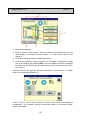
1.2. Description, Accessories
1
Mainframe. Rotary arm with stretching mechanism is hung on it.
2
Arm rotates around the wares and stretching mechanism moves vertically
on it.
3
Stretching mechanism. It carries a film-spool and ensures both correct
wrapping of wares including tightening to ensure better firmness of
wrapped pallet, and film stretching in order to reduce its usage.
4
Top platen mechanism for unstable wares is not part of the standard
package. It is suitable for light or unstable wares. It is a pneumatic
mechanism, which is ejected from the main tenon, and its correct position is
during the whole course of action secured by shear mechanism.
5
Ending mechanism. The machine is equipped with ending mechanism by
default. As per order, one of following two mechanism can be delivered:
• smoothing ending mechanism
• sealing ending mechanism
4
Pragometal s.r.o.
WRA TS
6
Film gripper. It is placed on a conveyor and works in co-operation with
ending arm. During the ending it grips the end of the film from the stretching
mechanism and at the beginning of the following wrapping it secures the
film on the pallet.
7
Overlap mechanism. Not part of standard package, it can be fitted per
order onto model PROFI only. It lays overlap film on top of the wrapping
pallet.
8
Conveyor. It serves to carry pallets with wares into the workplace of the
machine and to carry wrapped wares further on the line.
9
Switch-board with control panel.
10
Protection fencing. (not displayed). It is mounted as per project (see
Chap. 3.1) and ensures safety of manipulation staff as well as other people
in the vicinity of the machine.
Detail description of individual parts of the machine incl. its manipulation in
Chapter 5.
5
Pragometal s.r.o.
WRA TS
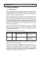
1.3. Wrapping Material
1.3.1. Wrapping Foil
The machine is designed for wrapping the wares on pallets with linear lowdensity polyethylene stretch film (LLDPE) with thickness of 20 ÷ 40 µm. The film
must have dilatability of 150%, be in spools of 500±10 mm in width and diameter
of maximum of 250 mm. The tube onto which the film is wound must have inside
diameter of 76±3 mm and length of 510±5 mm.
Both one-sidedly adhesive and non-adhesive film can be used. Adhesion of one
side means that individual layers wrapped around the wares will very well stick
together, yet they do not tend to damage the wares on the pallet in any way. The
main purpose of utilizing this film is to better set the wares on pallet, better
firmness of the wrapping and its bigger resistance against climatic effects and
mechanic straining during transportation. After wrapping a pallet with the wares, it
is recommended that the wound film be oriented with its adhesive side onto the
wares so that the pallets will not stick together with each other during
manipulation and transportation.
The film is normally resistant against UV radiation for 6 months, i.e. the wrapped
wares can be stored during this time outdoors and be exposed to the solar
radiation while keeping all original characteristics of the wrapping. If required to
be stored outdoors for longer time, some films can be supplied with better
resistance against UV radiation.
Stretch films meet above-mentioned requirements:
Model
POWERFLEX
HPQ
Dilatability
250%
Use
Possible variations
Various thickness
Automatic machines with
mechanical, single- or twin-engine Non-adhesive and onestretching mechanism.
sidedly adhesive
High UV radiation resistance
POWERFLEX
SPQ
300%
Use – similar as POWERFLEX
HPQ.
Various thickness
Non-adhesive and onesidedly adhesive
High UV radiation resistance
At wrapping machine setting in operation we recommend you to contact the
supplier or the manufacturer, which will recommend you optimum stretch film for
wrapping the wares from their experience.
We do not recommend using of packaging material other than stated here, e.g.
perforated films, reticular films, laminated films, printed films etc., without prior
consultation with and without permission of the manufacturer as a proper
functioning of the wrapping machine cannot be guaranteed. If, during guarantee
period, the machine wraps imperfectly, or if the machine or the wrapped wares
get crippled then usage of uncertified films or packaging material by the
manufacturer may be a reason for the claim rejection.
6
Pragometal s.r.o.
WRA TS
1.3.2. Overlapping film
The overlapping device (provided that it is fitted to the machine) should be
operated with a smooth non-stretching film of polyethylene (PE), thickness 50 to
80 µm, supplied in rolls. Without a consent of the manufacturer, an atypical film
may not be used (e.g. network-like, perforated, layered, with bubbles, made of
other material than PE, etc.). Concerning the machine design, no requirements
are defined for other properties of the overlapping film than those specified in this
chapter. Specific width of the film is given by dimensions of the wrapped goods
on the pallet and the wrapping method. The overlapping film on the roll of width
max. 1700 mm can be inserted into the machine ROTARY ARM 1700.
Diameter of the overlapping film roll is max. 250 mm. The film must be would up
on a tube the inner diameter of which should fall within 55 to 85 mm; the tube
must go beyond the roll face at both ends or must match with it. Concerning the
machine design, no requirements are defined for stretching ability or other
properties of the overlapping film than those specified in this chapter.
1.3.3. Environmentalism
The film can be included into assorted waste (polyethylene PE, to be precise).
The material is well recyclable. It can be easily burned and while keeping correct
combustion conditions, no harmful fouling originates. It is not biologically
decomposable and the decomposition in the dumping ground is very slow. No
harmful by-products to elude to the air or to pollute water or soil are known.
1.4. Machine Design
On condition of installation and running the machine according to the project
done under Chap. 3.1, the machine design conforms to relevant technical
regulations and standards and meets requirements of relevant safety and fire
regulations.
Standard and regulation requirements are included in the production
documentation. Precautions on the part of the user are described in this
accompanying technical documentation - service manual.
The expected machine lifetime is 10 year or 50,000 service hours, what happens
first, providing the machine is used in conformity with this accompanying
technical documentation and the specified maintenance and periodical checks of
the machine are kept.
1.5. Machine Operating Conditions
The wrapping machine is designed for operation in the ambience, which has to
meet following conditions:
Common ambience in terms of a Czech standard ČSN 33 2000-3 (IEC 364-3)
under the terms as set out further in this chapter and on condition of installation
and running in conformity with this accompanying technical documentation.
7
Pragometal s.r.o.
WRA TS
The machine must be fitted up and operated in sheltered operation premises
protected from atmospheric factors.
The floor must be level and braced, the maximum variation from the flatness of
the floor is ± 3 mm / 2m. Before fitting the machine in place, it is necessary to
remove dirt, chips etc. from the surface.
The temperature range for operating the machine should be between
+5ºC and +40ºC, the rate of change of the temperature be max. of 10°C / 30 min.
The relative humidity should be 30% ÷ 95%, without moisture condensation.
The machine can only be operated in the premises, which meet requirements of
governmental working condition regulations - regulation No. 178/2001 of the
Statute Book, "Government Regulation, which establishes conditions for health
protection at work" and Ministerial Regulation No. 48/1982 of the Statute Book,
"Regulation of the Czech Occupational Safety Authority, which establishes basic
requirements for ensuring occupational and machine safety".
It is not allowed to fit up the machine so that the access paths to the electric
installation would be reduced under the minimum values as set out in
governmental regulations, i.e. ČSN 33 3210 Distribution Equipment - Common
Provisions.
No obstacles, which could cause injuries of manipulators, may be placed in the
vicinity of the machine (e.g. stairs, platforms, drop ceilings, others machines etc.).
The product must not be used in the explosive atmosphere or where the
explosive atmosphere could arise even for a span.
The machine, and especially its electric installation, must be fitted up and
operated according to instructions of the manufacturer as mentioned in this
accompanying technical documentation.
1.6. Warranty
General warranty conditions are defined in the Warranty Sheet which is an
integral part of documentation accompanying the machine. The warranty sheet
must be duly and fully filled in and confirmed by the manufacturer.
Prerequisite for warranty is regular check and maintenance of the machine and
exclusive usage of original spare parts.
• Warranty does not apply to defects caused by:
• mishandling
• non-respecting the operating instructions of the product
• intervention into the product by unauthorized person or organization, and
• overloading.
Warranty also does not apply to:
8
Pragometal s.r.o.
WRA TS
• Tear-and wear parts specified in Chapter 8.2.1.
• Damage to machine or goods caused by using wrong consumable material,
other than approved by the manufacturer (see chapter 1.3).
1.7. Manipulation
The machine is designed for manipulation by one person. Working station at the
control panel in combination with specified protecting device ensure that the
manipulator will work beyond reach of the working space of the machine.
1.8. Electrical Installation of Machine
Electrical installation of the machine has been executed pursuant to EN 60204-1.
Electrical installation of the machine comprises of a switch-board and an electric
distribution on the machine. There are bipolar supply terminal and machine on-off
switch in the switch-board. Machine supply must be protected by fuses or circuit
breaker. The mains, to which the machine will be connected, must comply with
both international and national regulations and standards.
9
Pragometal s.r.o.
WRA TS
2. SAFETY INSTRUCTIONS
2.1. Revisions and Tests of Electric Installation
The machine is subject to regular revisions and tests of electrical installation. It is
necessary to meet requirements as set out in EN 60204-1 during those
operations.
The revision of electrical installation must be executed prior to initiation of the
machine - see Chap. 3.3.
2.2. Safety Recommendation
Since every unprofessional interference with electrical installation could cause
major damage to the machine or an injury to the personnel, any intervention can
only be carried out by person competent in accordance with national regulations
for electrical work..
Machine manipulators must be demonstrably familiarized with this service
manual and the manual must be made available to them at all times.
The main machine switch on the switch-board is lockable and it enables to lock
the switch in the off position. We recommend the machine user to sort out
handling of the key on the floor where the machine has been fitted up and thus
prevent the machine from running by unauthorized person.
2.3. Occupational Safety
2.3.1. Protective Devices for Occupational Safety
Dangerous places, which could endanger the manipulator during operation, are
secured by protective fencing, which is connected with the control system of the
machine; eventually, the project executed according to Chap. 3.1 must apply
safety measures, which provide equal health protection of machine manipulators
as well as other people in the vicinity of the workplace. If both, the specified
operation for wrapping and instructions as stated in this documentation, are met
the work with the wrapping machine is safe.
Dangerous places outside the working space of the machine result from
principles of individual activities of the machine:
1) Roller or chain conveyors enable independent movement of pallets with
wrapped wares.
To ensure safety of personnel, the following are used:
1) EMERGENCY STOP button for quick switch-off of the machine. The button is
mechanically blocked in on position and is placed within reach of the
manipulator on the control panel.
10
Pragometal s.r.o.
WRA TS
2) CONTROL VOLTAGE button. On power supply outage or upon touch of
EMERGENCY STOP button, the supply of control system is switched off and
the machine stops performing any activity, even if the supply is recovered
or the EMERGENCY STOP button is prematurely unblocked as a result of
accidental or inadequate action of the manipulator or service. Only the
touch of CONTROL VOLTAGE button enables further activity of the machine.
3) Machine control is executed from the control panel, which is placed on the
side of the machine, or independently as per the project. The control panel
is out of reach of working space of the machine.
4) There is a protective fencing around the whole machine, eventually
equivalent safety measures are used as per project as designed in Chap.
3.1
5) Ending mechanism. Control element (reverser) for opening and closing
film fixture is placed in a way that during its operating the mechanism of
film fixture is out of reach for the manipulator.
2.3.2. Duties of Manipulator and Machine User
For personal safety, the manipulator is obliged to follow these instructions:
6) The crew of the machine is made up of one person only. No other person
than the manipulator is allowed to be in the vicinity of the machine during
run.
7) Only a worker older than 18 years, who has been authorised for it and has
been familiarized with this manual and safety rules demonstrably, is
allowed to manipulate with the wrapping machine.
8) The manipulator must not be under influence of alcohol, addictive drugs or
drugs, which may influence safety at work.
9) During the operation, the manipulator must be beyond reach of the
working space, i.e. by the control panel.
10) The manipulator must operate and maintain the machine in accordance
with this manual. Material damage and injuries can be avoided, if the
machine is properly used.
11) The manipulator must check the whole machine a correct functioning of
its individual parts, mainly integrity of electric cables before work initiation.
12) During operation of the machine or the conveyor is prohibited to
manipulate with wrapped wares on roller or chain conveyor or with the
conveyor itself differently than specified in this manual.
13) To remove, dismount or lift off covers is only allowed after the machine
has been brought to a complete stop and the off position has been
secured.
14) Safety marking, symbols and signs on the machine must be kept in
legible condition. On their damaging or at their illegibility, the user must
restore the state in accordance with the original design.
11
Pragometal s.r.o.
WRA TS
It is prohibited:
1)
2)
3)
4)
5)
6)
7)
To use the machine for other purposes or otherwise than
specified in this service manual.
To start up and to use the machine, if protective equipment
(cover, keyboard sheet) is dismounted or damaged.
To touch moving palette.
To operate the machine, if working space of the machine
and workplace are not well illuminated.
To carry out maintenance, cleaning and repairs, if the
machine is not switched off with the main switch and
secured against accidental start-up.
To carry out checks or repairs of electrical installation by a
person without necessary qualification.
To put out of operation safety, protective and security
equipment or otherwise interfere with the installation and
electrical elements of the machine.
2.4. Health and Occupational Hygiene
Weight of the wrapping film is approx. 17 kg. To handle loads over 15 kg is
prohibited to all women and juveniles.
Working ambient, in which the machine is operated, is influenced by the nature of
manufactured and packed goods. The user is obliged to guarantee occupational
safety and hygiene of workers in conformity with national regulations for
occupational hygiene.
To reduce the physical effort, the manipulator must during manipulation with
packed pallets use hoist means of mechanisation, which have been assigned to
him by the employer.
If the nature of the packed product could lead in hand or any other injury of the
manipulator during operation, or if packed goods does not meet hygiene limits
(chemical and biological materials, dustiness, din etc.), the operating staff must
use personal means of protection that the machine user has given them for that
purpose.
2.5. Fire Protection
To ensure the fire protection during operating the wrapping machine, the user
must equip the workplace of the wrapping machine with relevant fire-fighting
means. Their purpose and placement must be consulted with and approved by
experts in fire protection and inspection, mainly in relation to nature of processed
material and to the fact that the wrapping machine is an electrical device.
The placement of fire extinguishers and their selection is done by fire-prevention
officer of the user according to local conditions.
12
Pragometal s.r.o.
WRA TS
2.5.1. Instructions for Machine Staff
In case of fire accident, the manipulator must in the first instance turn off power
supply by switching off the main switch.
To subsequently put out the emerged fire, the manipulator must only use the fire
extinguishers designed for it.
Neither water nor foam fire extinguishers are allowed during fire extinguishing!
13
Pragometal s.r.o.
WRA TS
3. ACTIVATION AND HANDLING
A supplying company normally executes machine assembly and activation. There
must be a three-phase supply and compressed air at disposal on side. For
parameters of power supply and compressed air see Chap. 4. After the assembly
and connecting to power supply it is necessary to carry out revision of electrical
installation before activation - see Chap. 3.3.
3.1. Project
Before the machine assembly, a project tackling the following must be drawn up:
• meeting machine ambient requirements (see Chap. 1.5),
• occupational safety of the personnel and other persons in the vicinity of the
workplace. Access to the working space of the machine must be barred during
the wrapping process by e.g. using protective fencing, light barriers, electronic
locks and other protective measures as needed,
• location and orientation of the machine within the wrapping line in term of
functionality of both, the machine and the line, and according to needs of the
packed goods,
• if the machine is fitted with the overlapping device it is necessary to minimize
airflow in the machine vicinity (the cut-off overlapping film is carried by the
airflow away from its optimum position and the overlap can be of poor quality),
• location of the switch-board and the personnel (in case the machine is
delivered without the switch-board, or with detached one),
• access to places of manipulation and places essential to maintenance and
repair works,
• mechanical, electric and software co-operation with other machines on the
line,
• supply of electricity and compressed air and cable guide so that neither the
supply and the cables could not be damaged, nor the manipulator or other
persons in the vicinity of the workplace be injured,
• positioning of more Emergency stop buttons if need be so that they would be
easily accessible for both, the manipulator and other persons in the vicinity of
the workplace.
• These times of emergency stop of the machine apply to calculating safe
distances according to ČSN EN 999 :
Machine version
1700
2300
Standard
1s
1,2 s
Profi
1s
1,2 s
The project may be drawn up by a company or a person knowing the rules of
occupational and machine safety as established by applicable international and
national law and standards. Safety of the whole workplace must be analyzed by
the supplier who is responsible for the solution and, if need be, prepares
14
Pragometal s.r.o.
WRA TS
guidelines for occupational safety. By default, the manufacturer or the supplier of
the machine drawn up the project.
3.2. Storage
If the machine is not put into service immediately after delivery it needs to be
stored in original protective wrapping in sheltered place protecting from
atmospherical factors (rain, snow). The range of storage temperature is between
0ºC and +55ºC, with humidity between 5% and 95% without moisture
condensation. Corroding agents or materials releasing vapours that may damage
cable insulation, or materials that may create combustible or explosive
atmosphere must not be stored on the same place as the machine.
3.3. Connection To Supply System
Electrical package of the machine comprises of a switch-board and distribution
through the machine. The main switch and five-pole supply terminal with U-, V-,
W-, N- and Pe-connectors are placed in the switch-board. The machine supply
must be secured with fuses and circuit breaker.
First check service voltage and machine frequence as shown on electrical
installation label with voltage and frequence of the mains, to which the machine
should be connected. Even voltage variation by maximum of 5% of face-value
ensures proper functionality of the machine. The mains, to which the machine will
be connected, must comply with all international and national standards and
regulations.
Outer protective terminals on the machine and contactor switch-board must be
connected to protection system of the user and be properly cured.
Before the machine is put into service, a proper functionality of the protection
against dangerous contact voltage as per IEC 60364-4-41 must be checked and
a revision of the machine supply cable as per IEC 60364-6 be carried out. The
revision must be executed by revision worker who meets national regulation
requirements.
The machine may be connected to the mains with the main switch after a
thorough examination of the supply and specified revision.
3.4. Machine Disassembly
On machine disposal after finishing its lifetime put all mechanism in such position
that no danger could arise from falling detached parts and that all dismounted
parts could be safely taken away. Remove supply connection by pulling the plug
out of the socket and compressed air by disconnecting from the supply. A person
competent under Chap. 2.2 checks remnant voltage in the electric circuit, if any,
before start of dismount; potential remnant voltage must be discharged.
Dismantle engines with gear boxes, drain the oil, which is to be stored in solid,
break-resistant and impermeable vessel.
15
Pragometal s.r.o.
WRA TS
Dismantle all parts of the machine.
Sort all parts according to waste classes (steel, non-ferrous metal, plastics,
cables, electrical elements etc.). Hand over the separated waste including oils to
specialized companies for its competent disposal.
16
Pragometal s.r.o.
WRA TS
4. TECHNICAL PARAMETERS
n
Max. pallet diagonal
Weight
1700
1330 kg
(per type, min.)
Proportions
Arm
(see type label)
Height
as ordered
Width
3000
rotary arm diameter
3000
Motor
2.2 kW / 50Hz 400 V
Revolution
30 rpm + 20%
Revolution direction
left
Film container motor
Air pressure
el. motor 550 W / 50Hz 400 V
Input
max. 1.5 MPa
Operational
0.6 MPa
Wrapping film spool weight
approx. 17 kg
Overlapping film spool weight
Conveyor
approx. 50 – 100 kg
Width
900
Height
as ordered
Length
3000 mm
Speed
0.2 m/s
Propulsion
Circuitry
roller conveyor:: el. motor 550W/50Hz
400V
Working voltage
3 × 400 V / 50Hz
Motor input
9.2 kVA (see type label)
Supply protection
40 A (see type label)
Control circuit voltage
24 V
Electric installation
protection rate
IP 54
17
Pragometal s.r.o.
WRA TS
4.1. Label
4.1.1. Type Label
Type label is placed on a bottom part of pillar and its identical copy is in the
switch-board to be protected from any damage. It includes following:
Name and address of manufacturer (supplier)
Product type designation
Machine serial number
Production year
Electrical scheme number
Machine weight (kg)
Supply voltage (V)
Supply voltage frequence (Hz)
Voltage protection (A)
Machine input (kVA)
Control circuit voltage (V)
Data on type label take precedence over any data about technical parameters or
other data in this documentation.
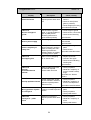
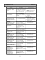
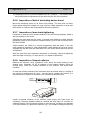
4.1.2. Other Labels and Tags
Labels and tags serving as source of information and warning of danger for
manipulators are shown in the tab. In case of them being damaged or lost,
restoration must happen.
The list shows all labels and tags that may appear on fully equipped machine.
Potential use restriction is shown in Use column.
Label
Manufacturer label
Vídeňská 1 72
Vestec
252 4 2 Jesenice u Prahy
Česká republika
TYP STROJE
VÝROBNÍ ČÍSLO
ROK
SCHEMA
HMOT.
Position
bottom part of pillar
copy inside switch-board
kg
V
Hz
A
kVA
V
lightning - warning of electric
shock in case of removed
cover
switch-board door
Scheme of loading film into
machine
arm, near film spool
18
Pragometal s.r.o.
WRA TS
5. EQUIPMENT
5.1. Stretching Mechanism
The film, for which the stretching mechanism is designed, is specified in Chap.
1.3.
Primary stretching happens between stretching mechanism rollers as a result of
their different rotation speed. The main outcome is film saving. Secondary
stretching happens between the stretching mechanism and pallet directly by
pulling the pallet against retarded rollers of the mechanism and it determines the
tightness of the wrapping (tightening of the film around the goods).
The entire stretching mechanism is mounted on a trolley, which moves along the
full length of rotation arm pillar.
The operation is controlled from a control panel of the wrapping machine.
!
!! WARNING !!
Any part of wrapping machine must not be in motion during any
work near stretching mechanism rollers.
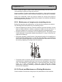
5.1.1. Single-engine Stretching Device
Working principle of the single-engine
stretching device is primary film stretching
between two main rollers, which are interlocked
via gear transmission. Gear ratio is typically
160% and can be adjusted by changing gear
wheels on rollers. Secondary film stretching
happens between the pallet and the main
roller, whose stopping power is determined by
a difference between motor speed and arm
rotation. Secondary stretching can be
controlled from a control panel, its range is
between 70% and 400%, with 100% meaning
that the film leaves the stretching mechanism
in such a speed that neither stretching, nor
shortening happens after wrapping on goods. Single-engine stretching device is
designed for plants with middle or higher capacity or packaging, demanding good
quality of wrapping and film saving and with no or less frequent request for
primary stretching value change.
The stretching mechanism is constructed from bearing structure, onto which main
rollers, their propulsion and gearing are mounted. Here are also mounted
secondary rollers ensuring proper and even application of the film on the goods.
19
Pragometal s.r.o.
WRA TS
Instructions for film initialization: Change empty
spool for a new one. Unwind approx. 1 meter of
the film from the spool, intertwine its end as
much as needed for loading into the stretching
mechanism and lead it between rollers
according to the scheme as stuck on the
device. The film will later straighten up again between the rollers during
operation. Act similarly on re-initialization after breaking the film.
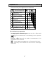
If not specified otherwise in the order, the primary film stretching is set to 160%,
which suits commonly used films and wrapping procedures. If you need to
change the primary stretching, you have a set of belt gear for different stretching
size from 80% to 290% at your disposal. Pinion and primary gear remain identical
for all values of primary stretching, only belt-gear wheel and secondary gear belt
need to be changed. Remove top cover of the stretching mechanism, unscrew
shaft axis bolts in belt wheels and pull down both wheels as well as the belt.
Conversely, mount new belt and new belt wheel together with the original pinion
(the pinion must always be on output shaft of the roller closet to electromotor).
Stretching
Wheel
Belt
No. of cogs
Order No.
Manufacturer No.
Order No.
80%
36
RTA-3.0-01-22
HTD-405-5M-15
1K-RE-0301
120%
44
RTA-3.0-01-23
HTD-425-5M-15
1K-RE-0302
160%
53
RTA-3.0-01-24
HTD-450-5M-15
1K-RE-0303
210%
62
RTA-3.0-01-25
HTD-475-5M-15
1K-RE-0304
250%
69
RTA-3.0-01-34
HTD-500-5M-15
1K-RE-0351
290%
79
RTA-3.0-01-27
HTD-525-5M-15
1K-RE-0305
Correct belt tension and procedure for setting are described in Chap. 8.2.9.
Maintenance of this device includes occasional check of belt tension and its
condition - see Chap. 8.2.9.
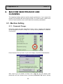
5.1.2. Measuring Height of Goods on Pallet
The wrapping machine is equipped with optical system for measuring the height
of goods on the pallet. This device is designed for automatic halt of the stretching
machine after wrapping top of the pallet. Optical sensor placed on the stretching
mechanism scans current height of the pallet as it travels with the mechanism.
From a moment when the sensor does not note any reflection (i.e. is above the
level of goods on pallet), the mechanism carries on with travelling upwards until a
moment as set up in the machine parameters and then stops.
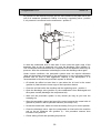
5.2. Ending Mechanism
The mechanism is controlled with operating system of the machine. It is designed
to stick the film to packed goods at the beginning and the end of wrapping; both
activities are fully automatic with no crew intervention. It is placed on the
conveyor or in its close distance in wrapping space of the machine.
20
Pragometal s.r.o.
WRA TS
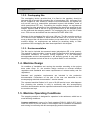
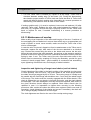
5.2.1. Ending by Sealing
Ending mechanism consists of three bars; while inactive, they are tilted under the
level of conveyor. For better illustration, the figure depicts all bars in upright
position.
1
2
3
1 – ending arm – device for film sealing and its cutting is mounted here
2 – back plate fixing wrapping film during the complete ending of the film
3 – film fixture. Its function is to hold the film between two consecutive wrappings.
The entire ending process can be described as follows:
• Back plate is ejected before the end of ending.
• Back plate is wrapped with the wares to the pallet.
• Film fixture fixates the film between the stretching mechanism and the pallet at
the end of wrapping. Ejected back plate ensures quality sealing.
• Ending arm and back plate tilt back and conveyor carries away the wrapped
pallet.
Sealing arms and film fixture are powered by compressed air.
!
!! WARNING !!
Risk of scorch! Overburning wire and sealing device are red hot for
a short time during cutting and sealing the film.
21
Pragometal s.r.o.
WRA TS
5.3. Top platen Mechanism
The mechanism serves for fixing unstable, light goods during wrapping. It is not
part of standard package and has to be ordered extra.
Shearlegs top platen device attached to rotary arm can be used. Adherence
pressure of approx 300N (30kg) is developed by self weight of part of the
mechanism.
5.4. Overlap Mechanism
The mechanism is not part of standard package and has to be ordered extra. If
the mechanism is not requested with the initial delivery of the wrapping machine,
it cannot be supplied later - machine frame with the mechanism is not identical
with the one without it.
The mechanism serves for protection of upper area of packed goods against
atmospherical factors. Edges of protection film are fixated to pallet with stretching
film.
Overlap film can be laid automatically - command to overlap the pallet is sent in
the program of the wrapping machine so that the entire overlap process is done
without any intervention of the manipulator. Adjustment of the process is possible
only by setting optical sensors and changes in program and operation
parameters.
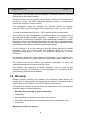
5.4.1. Description of Overlap Mechanism
1
Container with overlap film
2
Static tongs hold end of overlap film from spool.
3
Chain blade. Resistance cutting wire is mounted on it. Overlap film is cut by
red hot wire.
22
Pragometal s.r.o.
4
WRA TS
Mobile tongs pull loose end of the film so that it could be cut properly, and
then lay cut film on top of the goods on pallet (mobile tongs are not drawn in
the figure. For illustration, the figure shows a moment, when the tongs are
off their starting position).
5.4.2. Operation Description
Operation of the overlap mechanism can be divided into following phases:
1
Starting position: The overlapping film is inserted into the machine and
fastened in the fixed tongs. The moving tongs are in their starting position.
2
Film cutting. The moving tongs catch the film end, the fixed tongs open and
release the film. The moving tongs stretch the film to required length in the
vertical direction and then stop. The fixed tongs close again and catch the
film. The cutting bar cuts the film.
3
Moving of overlap to the goods. The moving tongs with the cut-off film move
in horizontal direction to the goods and find the upper edge of the goods in
the vertical direction.
4a Standard overlap (laying of the film by horizontal movement): The moving
tongs lay the film by horizontal movement to the top of the goods on the
pallet.
4b Combined overlap (laying of the film by horizontal and vertical movement at
the same time): The moving tongs move vertically to the preset height for
the combined overlap and start laying the film by horizontal movement; after
they have run the preset horizontal distance, they start moving down. This
procedure reduces the risk of damaging the overlapping film by the sharp
upper edge of the goods on the pallet.
5
Return. All mechanisms move back to their starting positions. The
mechanism is prepared for laying the overlap on the next pallet.
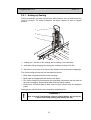
5.5. Lifting Mechanism
Lifting mechanism is optional (delivered per order) and is located under the
conveyor in wrapping machine axis. Before start of the wrapping, it lifts packed
pallet by 10 to 15 cm and thus enables to wrap the wares including the pallet (so
called under-wrapping), which fixates the goods to the pallet. It is mostly used
with light or unstable goods. The lifting mechanism is controlled automatically by
control system of the machine without any intervention by manipulator. Inclusion
23
Pragometal s.r.o.
WRA TS
of the operation of the lifting mechanism in the program is set in relevant
parameter of the machine system (see Chap. 6.6.2).
5.6. Protection Fencing
Protection fencing guarantees manipulator’s safety. It makes it impossible to
activate the machine, if there is a man in front of the fencing, i.e. it does not allow
anybody to stand in front of the fencing during operation. Electric lock and its
manual manipulation are controlled by machine control system. Control elements
of the fencing (electric lock buttons) are located outside the main panel of the
switch-board, just beside doors to the fencing.
Protection fencing is perfected with light barriers, see Chap. 5.7.
5.7. Light barriers
Light barriers support the protection fencing by guarding roller conveyor at
entrance and egress to the working space of the machine. In case of an attempt
to enter the working space of the machine using conveyor, the machine is
immediately switched off.
Category 3 safety elements as per ČSN EN 13849-1 are used. Operation of light
barriers is fully automatic and does not depend on the personnel. Light barriers
status is indicated as text on display and with bollard.
Light barriers protection function is moderated for essential period during passing
the pallet into the working space of the machine (function muting). light barriers
stop working during this period and unauthorized access is enabled. There, the
access on the conveyor must be physically disabled by light barriers, by
protection fencing reaching the light barriers and by mounting the light barriers
just beside conveyors to disable the access between pallet and light barriers.
Activity of light barriers is indicated with bollard.
Line Status
Standard status (machine is on and light barriers work as
normally)
Mute status (muting - pallet with goods is just passing the light
barrier)
Emergency status (attempt to enter the space, accident or fallen
goods in the light barrier)
Bollard Status
lit
not lit
blinking
Barrier protection function can be muted manually from serious reasons. More
information – see Chap. 7.4.
24
Pragometal s.r.o.
WRA TS
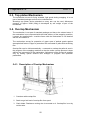
5.8. Control Panel
5.8.1. Switch-board Panel
Contains all controllers needed for machine manipulation, with exception of
protection fencing door operating.
ZAPNUTO
START
PORUCHA
STOP
AUT
1)
2)
+
3)
4)
25
Operator panel
TOTAL STOP button (machine
emergency switch-off)
CONTROL VOLTAGE button
MAIN SWITCH
Pragometal s.r.o.
WRA TS
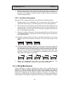
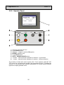
5.8.2. Operator Panel
1)
2)
3)
4)
5)
6)
7)
8)
MACHINE ON
START
FAULT
STOP
AUT
+
-
Operator panel MT 057 TST
Cycle START button
Indicator – voltage in machine ON (green)
DEFECT indicator (red)
Cycle STOP button
AUTO – MANUAL MODE switch
+ button – manual function operation of machine – one direction
– button – manual function operation of machine – different direction
The machine is fitted with control system LGA. Touch operator panel MT 057
TST serves for connecting the operator with programmed robot. It enabled the
operator to edit program and operation parameters, to choose manual function
type and to display possible errors.
26
Pragometal s.r.o.
WRA TS
Graphic LED display is used on the panel. Displayed buttons serve for data input,
changing displays and panel operating. Their location and purpose are adapted
to usefulness and comfort of the personnel to the maximum extent.
Durable mechanic buttons "+" and "–" on the switch-board serve for direct
manipulation of manual functions.
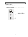
5.8.3. Special Buttons
The rest of the buttons and controllers are only used in some machines to help
with particular needs. They are not necessarily placed on the control panel or in
its vicinity, yet there, where it is more practical in terms of functionality and safety
(e.g. near controlled element). If your machine does not feature these buttons or
controllers, please ignore their description.
Two-phase controller FILM FIXTURE. Default position during
operation is Closed (controller left). Film fixture is mounted on
the conveyor; it grabs loose end of the film from stretching
mechanism at the end of wrapping and holds it till the next
wrapping.
Two-phase controller OVERLAP STATIC TONGS. Default position
during operation is Closed (controller left).
5.9. Safety Equipment
The machine is fitted with several safety elements for manipulator’s health
protection or minimizing damage after accidents.
27
Pragometal s.r.o.
WRA TS
5.9.1. Emergency Stop Button
EMERGENCY STOP button is placed near control panel and serves for immediate
machine halt in case of emergency (machine failure, fallen goods from pallet,
crash, injury). By pressing it, the button is automatically locked in on position, to
re-start the machine, the button must be unblocked. Pressed EMERGENCY STOP
button is indicated by an indicator on panel. To re-start the machine, follow these
steps:
Remove cause of emergency stop
Check condition of the machine:
Film must be correctly loaded in the stretching mechanism
Unblock EMERGENCY STOP button by turning it right (indicated by arrow on
button) until the button return into initial position
Finally, control voltage of the system must be switch on before starting the
machine (CONTROL VOLTAGE button) – see Chap. 5.9.2.
5.9.2.
Control Voltage Button
This button and its function as a stopper in case of unexpected or unwilling
behaviour of the machine after its start, breakdown, power outage or presence of
EMERGENCY STOP button signal meet requirements of Czech and European
safety standards. On power outage or after pressing EMERGENCY STOP button,
power supply of the system will be disconnected and the machine will not carry
out any activity, even if the supply would be restored or the EMERGENCY STOP
button would be unblocked by mistake or any other unauthorized intervention.
Only pressing the CONTROL VOLTAGE button enables further activity of the
machine. This button must also be pressed on machine start-up. Power supply is
indicated with button illumination, which is turned off after disconnection of the
supply.
28
Pragometal s.r.o.
WRA TS
6. OPERATING STAFF
This service manual has been drawn up for maximum machine configuration. If
your machine does not include some of the described parts, please ignore
respective chapter.
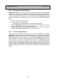
6.1. Machine Start-up and Shutdown
To ensure proper machine operation, this procedure on how to active the
machine must be followed:
• Press MAIN SWITCH
• Visually check situation on the line (pallets are correctly loaded with goods not
colliding with the machine, the line or each other. There are no strange objects
on the line or in the working space of the machine. There is nobody in the
working space of the machine. Safety equipment is OK and in correct position)
and switch on the control voltage by pressing CONTROL VOLTAGE button
• Displaying of machine initialization display (this display is displayed after each
make of power circuits - after closing doors etc.)
• When the conveyor line is controlled by wrap machine system, the START
button is displayed visually check situation on the line (pallets are correctly
loaded with goods not colliding with the machine, the line or each other. There
are no strange objects on the line or in the working space of the machine.
There is nobody in the working space of the machine. Safety equipment is OK
and in correct position) and if everything is OK, by pressing START button you
initialize the machine and line. If not, all problems must be rectified - see
Chap. 7.
Next procedure depends on mode of machine – automatic (see chap. 6.5) or
manual (chap. 6.7).
Only the main switch needs to be turned off on machine shutdown.
29
Pragometal s.r.o.
WRA TS
6.2. Touch Display Control
6.2.1. Basic Terms
For comprehensibility, following terms are defined for purpose of this manual:
Panel (display panel) – technical device mounted on switch-board and designed
for communication between manipulator and machine system.
Display – what is displayed on the display panel.
Button – control button visualized on the display. It is visualized protrudently, as if
being real button.
Keyboard – mean of touch panel system for inputting number or character
values.
6.2.2. Common Rules
Buttons of basic functions are placed on the right edge of the panel. Only those
buttons, which are of some concern for given display are displayed. See the text
below for detail description of functions of individual buttons.
One level up.
Saving parameters or programs into memory. A dialog box is
displayed that enables saving and also protects the system from
undesirable interventions.
Help.
ACK button – error message confirmation; it is only displayed in case
of error or failure. See Chap. 7
Move up (go to previous page)
Move down (go to next page)
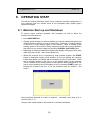
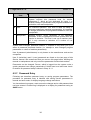
6.2.3. Number Values Input
Examples of editing program parameters are shown in following chapters. The
same procedure applies for editing operating parameters. Parameter values in
examples are illustrative and may vary from your machine.
We are going to set speed of 100% for arm rotation in following example.
30
Pragometal s.r.o.
WRA TS
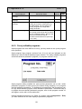
After pressing button with number value of Arm Rotation Speed parameter
number keyboard is displayed.
A
Help row (marked as A) shows range of possible values. Type in requested value
of "100" on the keyboard. Press Ent to confirm. The keyboard disappears and a
new parameter value is displayed on the main display.
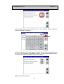
Del button deletes last digit.
31
Pragometal s.r.o.
WRA TS
Clr button deletes contents of the whole line.
By pressing Esc button, you cancel the option and return on the main display of
the automatic mode without any change of program set-up. In this case, the Arm
Rotation Speed parameter stays with original values of 70%.
When granted by a parameter, the keyboard displays a button with decimal point.
Similarly, when negative values are enabled, the keyboard displays a button with
minus sign ("-").
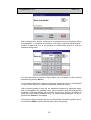
6.2.4. Value Change YES-NO
Some parameters can only bear YES or NO value. In following example, we want
to use pallet lift.
Values are switched when you press relevant button. After pressing Use Pallet
Lift button, the parameter value changes (in this example to YES).
32
Pragometal s.r.o.
WRA TS
6.2.5. Text Value Input
Display with alphanumeric keyboard is displayed on insertion of text values.
Alt button switches between data input of characters A-W and X,Y,Z, numbers,
and space and symbols.
By touching Ent button you save the inserted text into memory and return on
initial display.
Del button deletes last inserted characters one by one.
Clr button deletes entire string.
Esc button cancels data insertion and closes the panel. Edited text remains
unchanged, as before editing.
6.2.6. Password Protection
All programs and parameters can be viewed without restriction, password
protection works when an attempt is made to change and save parameters or
program. Exception is made for password editing (Chap. 8.1.1) and language
change (Chap. 8.1.2). The machine and parameters are protected on various
levels according to their purpose and importance:
User
8
Administrator
Only for manufacturers and service companies. It is
required for service parameters 2, which are not desirable
to be changed without good knowledge of the machine
and the system. It allows a change of all machine
parameters and programs, which are available for
administrator, technician, user and manipulator.
33
Pragometal s.r.o.
WRA TS
User
5
Technician
For company maintenance and machine administration
System requires this password level for service
parameters 1, which are not dedicated for users 1. It
enables change of parameters and programs available for
technician, user and manipulator.
2
User
For machine operation. This level is used for setup of
program parameters (machine programming). It is possible
to change parameters and programs available for user and
manipulator.
Manipulator
General access. Given parameter is not password
protected, it can be changed at will and system does not
require its insertion. This level is set up at machine startup. It only concerns a selection of a number of run
program.
System itself manages password insertion, it requests it only when you try to
select a password protected function (i.e. attempt to save changed program
parameters or values of machine parameters).
User 8 password (administrator) is only known to the manufacturer and service
companies.
User 5 (technician) and 2 (user) passwords are listed on the last page of this
Service manual. We recommend that you remove this page before handing the
manual to manipulators and only reveal the passwords to authorized workers.
Passwords can be changed. Person, which is logged into the system under a
certain password can change passwords of his/her own level and lower levels.
Procedure for password setup is shown in Chap. 8.1.1.
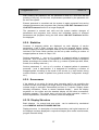
6.2.7. Password Entry
Following text describes password entry on saving program parameters. The
procedure for password entry is identical with saving service parameters in
manual and auto mode, for display language change and others.
You have altered a program, want to save the changes and a valid password has
not been entered. Crossed ring is displayed on a display for parameter saving on
SAVE button.
34
Pragometal s.r.o.
WRA TS
After pressing Save button, a dialog box for password entry is displayed. Entry
the password - it comprises of maximum of 8 digits. Keyboard display shows *
instead of digits and so it is not possible for unauthorized person to read the
password during entry.
****
Four-digit password is entered on figure above as an example. Confirm entered
password by pressing Ent key.
If the password has been entered correctly the crossed-ring icon is not displayed
on any of Save buttons, for which the password authorizes saving.
With incorrect password entry will the password keyboard be displayed again.
After pressing Esc, the password entry will be cancelled and the keyboard will
disappear. Preceding display will be shown and there is always a possibility to
leave this mode without password entry, i.e. without saving changes - to do so,
press button Cancel on the display.
Only buttons without crossed-ring icon are functionally. Required operation (here,
the command SAVE) will be executed after button re-pressing.
35
Pragometal s.r.o.
WRA TS
Entered password remains valid, LOG OUT Password button is displayed on
main panel of auto mode during this time:
The same button is displayed on the display during manual mode, if you switch
on it or if you edit service parameters.
36
Pragometal s.r.o.
WRA TS
After entering the password, the set password is valid for 5 min from the last
pressing of any key; for this time, all parameters permitted by the password can
be set in the system.
Entered password is cancelled and the system is again protected from saving
changed parameters and programs after pressing LOG OUT Password button.
LOG OUT Password button is no longer displayed.
The password is entered and valid and the system enables changes of
parameters and programs, their saving and immediate testing of changed
parameters and programs during the time when LOG OUT Password buttons
are displayed.
6.2.8. Statistics
Counters of wrapped pallets are displayed on main displays of service
parameters 1 and 2. Both counters only count fully wrapped pallets; pallets,
whose wrapping has been interrupted either by user or following a failure, are not
included in the count. Both counters can be set up after touching a number of
wrapped pallets as shown in Chap. 6.2.3.
Service parameters 1 - set up of a number of wrapped pallets is password
protected - level 5 technician. It is designed for monitoring a number of wrapped
pallets according to the needs of the user (e.g. number of pallets per shift, week,
month, for a delivery order etc.)
Service parameters 2 - set up of a number of wrapped pallets is password
protected - level 8 administrator. It is designed for monitoring a number of
wrapped pallets according to the needs of the service (e.g. total number during
machine lifetime, number of pallets from general revision, configuration change
etc.).
6.2.9. Screensaver
If the display is not active for longer time (operating staff is not controlling the
machine via the touch display for longer time) a screensaver with dark and noncontrast image is activated. Automatically set time is 7 minutes. Display shows
following information: "Press to restore standard display" - touch the display
anywhere on its surface and the standard display as left before screensaver
activation appears. This switch does not bring any other operation, neither it
actives a parameter, command or function, which are displayed.
6.2.10. Display Structure
Basic displays - for manual and auto mode - can be switched by mechanical
switch MANUAL AND AUTO MODE SWITCH.
Display structure, i.e. description of mutual dependency and logical sequence of
the displays is always displayed in respective chapter (auto mode, manual mode,
program free edit mode).
37
Pragometal s.r.o.
WRA TS
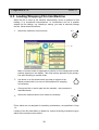
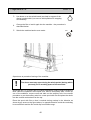
6.3. Loading Wrapping Film Into Machine
When the film is used up the machine automatically moves to position for film
loading. If, in exceptional circumstances, i.e. mechanisms are not in position
suitable for film change, e.g. following a tearing, you need to manually change
the film, follow these instructions:
1
Switch the machine to manual mode
AUT
A
Menu of manual mode for approach to position for film change and to initial
position appears on the display. This menu always appears as the primary
one after switching to manual mode.
3
Use button + on the switch-board (see help in top part of the
display marked with A) to move to initial position for wrapping
as necessary.
4
Change the film or load it again into the machine - the procedure is
described below.
5
Switch the machine back to auto mode as necessary.
AUT
Films, which are not designed for stretching mechanisms, are specified in Chap.
1.3.
Loading of the film itself differs in details for various stretching mechanism types,
which are mounted on the machine:
38
Pragometal s.r.o.
WRA TS
1
Put the machine in initial position, if needed, using + button in
manual mode (on the main display of manual mode).
2
Place film spool on spike and load it into the stretching
mechanism using procedure suitable for your stretching device
type as per Chap. 5.1.
3
Open film fixture using controller on back side of the switchboard.
4
Load film end into the open film fixture. Close the film fixture
using auxiliary controller.
The film is loaded and the machine is ready for further
operation.
Reload torn film using similar way of loading.
6.4. Loading Overlap Film Into Machine
We advise that spool with overlap film weights approx 60 to 80 kg.
Wait until all machine mechanisms have come to halt.
Overlap mechanism is in initial position by default, i.e. mobile tongs are in upper
position. If it is not so from any reasons follow these instructions:
1
Switch the machine to manual mode
AUT
A
Main display of manual mode appears on the display.
39
Pragometal s.r.o.
3
WRA TS
Use button + on the switch-board (see help in top part of the
display marked with A) to move to initial position for wrapping
as necessary.
4
Change the film or load it again into the machine - the procedure is
described below.
5
Switch the machine back to auto mode.
AUT
Open doors to protection fencing of the machine.
!
The doors must stay open during the whole period, during which
person(s) are in working space of the machine!
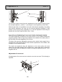
Spool with film (1) is loosely laid in unwind mechanism under overlap mechanism
itself. Remove it upwards. In the spool core, there is an auxiliary axis - loosen up
one of the wobblers, remove cone and take out the auxiliary axis. Use reverse
procedure to put the auxiliary axis into a new spool with film and place the whole
into the unwind mechanism from the top.
Place the spool with film so that it unwinds during overlap in the direction as
shown by an arrow on the figure above. In opposite direction could the unwinding
be more difficult and the film could slip from mobile tongs.
40
Pragometal s.r.o.
WRA TS
To open the tongs, switch OVERLAP STATIS TONGS (2) button to
position right.
Unwind required amount of overlap film from the spool and load it in between
jaws of static overlap tongs (3). To ease manipulation, unwind approx. 10 to 15
cm more of the film and fold it over static part of the tongs.
To close the tongs, switch controller (2) to left (initial) position. The film is loaded.
Leave working space of the machine and close doors to protection fencing.
The machine is ready for further operation.
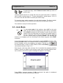
6.5. Auto Mode
To enter auto mode of the machine, select AUT on the main
panel. As the machine is designed for work mainly in automatic
lines START command for the machine is given by the control
system of the line depending on movement of packed goods on
the line. Automatic cycle of the machine can also be switched
on from control panel by pressing START. The machine will
execute one wrapping cycle as according to the entered program after START
command.
AUT
Auto mode of the machine can be suspended by pressing STOP at anytime. After
pressing START button, the machine moves to initial position, if
not on it already, and a new wrapping cycle begins. The film can
be finalized before re-start by using manual function Full Ending
(see manual functions, Chap. 6.7)
Next step be valid only when conveyor line is controlled by wrapping machine
system: If there is a pallet on the conveyor under rotary arm after machine startup or switch to auto mode, system message will appear on the display:
Press YES to execute wrapping. If NO is selected, the pallet is considered
wrapped and is carried away from the machine.
41
Pragometal s.r.o.
!
WRA TS
WARNING !
Only manipulating person can be in the vicinity of the machine.
The machines support up to 20 wrapping programs with numbers 0 to 19.
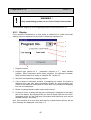
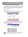
6.5.1. Display
If the machine is switched on in auto mode or switched in it, initial auto-mode
display screen is displayed for the mode, in which the machine runs.
1
2
3
4
5
6
1
Program number.
2
Program type (shown as P - parametric program or F - freely editable
program. More information about these programs, the difference between
them and their features is shown in Chapters 6.6.1 and 6.6.3.
3
Short info text describing wrapping program.
4
If the machine is delivered inclusive of wrapping line control line status is
displayed here and also other information needed for entire wrapping line
control. If the machine is delivered solo and does not command the wrapping
line row is not displayed.
5
Button for edit parameters option and machine set-up.
6
In case of errors, a rolling text with error messages is displayed in the upper
part of the display. By pressing ERR you enter a display with the list of error
messages where you can find more information about particular error and its
possible solution. See Chap. 7
Also, if the machine is in error state after start-up a yellow button ACK as well as
error message are displayed - see Chap. 7.2.
42
Pragometal s.r.o.
WRA TS
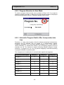
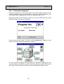
6.5.2. Program Selection In Auto Mode
To select a program, follow similar rules as shown in Chap. 6.2.3. If you want to
change a wrapping program, a dialog box for new program selection is displayed
after touching program number on standard display of auto mode.
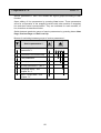
6.5.3. Automatic Program Switch After Incorporation Into
Line
Remotely, i.e. using control system of the line without manipulator’s intervention,
programs can be switched over by means of 3 communication signals.
Parametric programs 0 to 3 and freely editable programs 10 to 13 are used for
remote switching. To activate this function, one of following programs must be
manually set up. The function is inactive following different program number
selection, i.e. program 4 to 9 or 14 to 19) and the wrapping is executed according
to program selected on operator panel.
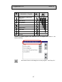
Tab. Assignment of combination of communication signals and programs
Communication signal
Category 1
Category 2
Category 3
Program 0
0
0
0
Program 1
1
0
0
Program 2
0
1
0
Program 3
1
1
0
Program 10
0
0
1
Program 11
1
0
1
Program 12
0
1
1
Program 13
1
1
1
43
Pragometal s.r.o.
WRA TS
6.6. Programming of Operation of Machine
Program number or program parameter can be changed at any time, even during
program execution. If wrapping cycle is being executed during program or
parameter change, parameters valid at the time of start of wrapping are used.
Changes in program or program parameter as changed during program
execution will take effect during following program start after the changed
parameters have been saved.
Entering program mode
Enter the program mode in auto mode by touching Configuration button. It is not
important whether the program you want to edit is set up or not; you will do it in
the next step.
If you wish to edit program, which is offered on following display (No. 3, in this
case), press Edit to enter edit mode of the parameters of the selected programs.
If you wish to edit different program, select its number as shown in Chap. 6.2.3
and confirm by pressing Edit button.
Should you have entered this display in error, you can return on the main
display by pressing Back or One Level Up button - both buttons are
44
Pragometal s.r.o.
WRA TS
equivalent.
Note: other displayed button do not relate to programming (buttons Service 1,
Service 2 and Line relate to service parameters of the machine in Chap. 6.8,
ERR button serves for displaying and processing error messages - see Chap. 7).
Program Mode Termination
You can leave service parameters editing display upon pressing Save
button, or Save, back) to get to dialog box display for saving changed
parameters.
1
2
3
5
4
1. Input field displays number of a program being currently edited. If you wish to
save the program under different number, a keyboard will pop up after
pressing program number (see Chap. 6.2.3) and you can enter a number,
under which you want to save the program.
2. Short description line. It serves for better orientation of the personnel,
maximum of 20 characters can be inserted here to describe the program.
Upon touching this line, a dialog box for entering text string pops up - see
Chap. 6.2.5
3. SAVE button. If a crossed ring is displayed on this button (as shown on the
picture), parameters saving is password protected; upon pressing this button a
dialog box for password entry is displayed (see Chap. 6.2.7) and after repressing of SAVE button is the program saved. If no crossed ring is displayed,
valid password has been entered and program can be saved directly and main
display of auto mode will pop up.
4. Edit Back button. If you forget to change any parameter, you can use this
button to return to parameter editing.
5. Cancel button. Changed program is not saved and main display of auto mode
is displayed. This button can also be used if saving is password protected and
you don’t know it.
45
Pragometal s.r.o.
WRA TS
6.6.1. Parametric programs
Parametric programs can be relatively easily set up and enable reliable and costeffective wrapping under normal conditions. Use freely editable programs if you
have bigger call for wrapping and the way of wrapping (Chap. 6.6.3).
Parametric programs have program number 0 to 9 and are indicated with a letter
P beside program number on the display.
Using process as per Chap. 6.6 (button order Configuration - Edit) you have
switch to the main display for parametric programs.
You can access the display with parameters for respective wrapping part from
the main display of parametric programs. Switching between pages using buttons
Next Page, Previous Page and One Level Up is transparently shown in tab.
46
Pragometal s.r.o.
WRA TS
Parameters - Program
Main display of parametric
programs
Basic set-up
Low position
Upward
High position
Downward
At the end
Overlap
Number of edited program and displayed part of program are shown in the
display heading.
Use button Save to call dialog box to save program - see Chap. 6.6
47
Pragometal s.r.o.
WRA TS
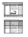
6.6.2. Automated Wrapping Cycle Parameters
Text Displayed
Parameter Name
Values
Unit
Basic set-up. Activities to be performed by the machine are defined here (what
mechanisms are to be used during wrapping)
YES/NO
Wrap
Wrap Yes: Full wrapping sequence will
be executed after start-up.
Wrap No: Pallet will only pass through
the machine
Use top platen
If YES, top platen is used during
wrapping
YES/NO
Use overlapping
If YES, Overlap is used during wrapping
YES/NO
Use wrap.with
ejected fixture
Use wrapping with ejected fixture
YES/NO
Use pallet lift
If YES, wrapping starts with erected film
fixture, if NO, the fixture is down.
Erected spike is important if ground
plan of packed goods is smaller than
that of pallet. If it’s the case, initial
tapered part of film is laid on pallet.
If YES, pallet lift is used during wrapping
(i.e. the wares is wrapped with the
pallet - under-wrapping)
YES/NO
Low position - wrapping parameters in low position as used at start of wrapping when
the stretching mechanism is down. Main purpose of this phase of wrapping is to firmly
and reliably fixate start of the film to the goods and part of the goods to pallet.
No. of Arm Turns
Number of turns at start of wrapping in
1-9
turns
low position. Only after completing
these turns the stretching mechanism
starts to go up. The turns fixate the film
to pallet.
Spinning speed of
Spinning speed of arm during turns in
0-100
%
arm
low position
Secondary stretch
Secondary film stretch during turns in
60-150
%
low position
Upward. Used when stretching mechanism moves up along the pallet. Ordinary
wrapping phase.
Spinning speed of
Spinning speed of arm during stretching
0-100
arm
mechanism travel upwards.
Stretch.mech.travel Stretching mechanism travel speed
speed
Speed of the stretching mechanism on
the arm during travel upwards
Secondary stretch
Secondary film stretch during stretching 60-150
mechanism travel upwards
%
%
%
High position - wrapping parameters in upper position. During the period when the
stretching mechanism is in upper position above goods and eventual activity of Overlap
mechanism is happening. The main task is to fix upper part of goods to pallet.
48
Pragometal s.r.o.
Text Displayed
No of Arm Turns
WRA TS
Parameter Name
Number of turns in upper position after
start. These turns fixate upper part of
packed goods to pallet and if overlap
film is used they fixate it as well. Film
end is also fixated during simple
wrapping.
F.overlap ab.edge of Film overlap above edge of goods
goods
Distance, which is used for overlapping
of upper part of film above edge of
goods on pallet. Edge of goods is overwrapped. Film protects edges of
packed goods and eventually fixates
overlap film, if used.
Spinning speed of
Spinning speed of arm during turns in
arm
upper position.
Secondary stretch
Secondary film stretch during turns in
upper position.
Values
Unit
0-9
turns
cm
0-100
%
60-150
%
Downward – wrapping parameters downwards. Used when machine moves
downwards along the goods on pallet.
Spinning speed of
Spinning speed of arm during stretching
0-100
arm
mechanism travel downwards
Stretch.mech.travel Stretching mechanism travel speed
0-200
speed
Speed of the stretching mechanism on
the arm during travel downwards
Secondary stretch
Secondary film stretch during stretching 60-150
mechanism travel downwards. Only
used for double (cross) wrapping.
%
%
%
At the end – wrapping parameters at the end of wrapping. Used for end of wrapping.
These parameters need to be set up so that wrapping is optimally finished and
stretching mechanism film is properly fixed in film fixture.
No of Arm Turns
Number of turns in low position before
1-9
turns
wrapping end in case of double (cross)
wrapping. These turns fixate film end.
These turns do not include turns
needed to finalize the film.
Spinning speed of
Spinning speed of arm during final turns
0-100
%
arm
Secondary stretch
Secondary film stretch during final turns
60-150
%
Overlap – overlap wrapping parameters. Set up these parameters so that overlap film
has optimum length, is evenly laid on top of goods on pallet and is properly fixed by
stretching film.
Overlap film length Overlap film length. Overlap film is cut
80-200
cm
to this length from spool.
Overlap film shift
Distance from rotary arm centre, by
0-80
cm
which cut overlap film shifts in
horizontal move over the goods on
pallet. The parameter is used to centre
the film on goods and to align it.
49
Pragometal s.r.o.
Text Displayed
WRA TS
Parameter Name
Values
Unit
No of turns after
overlap
Number of turns after overlap
0-100
turns
Sec.stretch after
overlap
Secondary film stretch after overlap
60-150
%
0-300
cm
YES-NO
–
Height of pallet for Height to which the moving tongs of
overlap
overlap drive before measurement of
the pallet height. For the value 0 the
moving tongs drive to height after
cutting off the film
Combined overlap
When Yes is chosen for this parameter,
the overlap will be laid by the procedure
for the combined overlap – laying of the
film by horizontal and vertical
movement at the same time (see chap.
5.4.2, 6.8.2)
6.6.3. Freely editable programs
Open programs are more difficult to set up, yet they enable to set up the program
more precisely.
Open program bear program numbers from 10 to 19 and are indicated on the
display by a letter F placed beside program number. The treely editable programs
cannot be saved as parametric program (i.e. program number 0 to 9).
Open program editing enables the most precise parameter set up and, unlike
parametric programs, to alter most of the values during wrapping, or to program
special wrapping procedures. To facilitate the programming, we recommend you
to copy similar suitable program, either editable or parametric. The easiest way is
to prepare the most similar parametric program, save it with program number 10
and higher, and to edit it in free edit mode.
Having followed procedure as in Chap. 6.6 (button order Configuration - Edit)
you have switched to the main display of parametric programs.
50
Pragometal s.r.o.
WRA TS
Left part contains list of six lines of the program. Line marked in yellow is the
active line and serves for direct editing (line number 7 on the picture). Press
command on the active line to display list of commands.
3
1
2
1
Use Up/Down arrow (1) to move in the parameter list. Press-and-drag scroll bar
(2) enables quick shift in command list. If you press selected command combo
list will be closed and the command is displayed in the active line. Existing
command will be overwritten.
Touch the parameter and activate parameter value editing - see Chap.6.2.3.
Some commands have no parameters so touching them will cause no action.
Tab below shows functions of individual program buttons. For simplicity, the
examples are generic and simply illustrate displayed commands.
Active line is in bold.
51
Pragometal s.r.o.
WRA TS
PAGE UP button. List will display commands on previous page.
Command
Command
Command
Command
Command
Command
8
9
10
11
12
13
Press PAGE UP
Commands will move one page up; current first line will show on the
last line of the new display (line with command No. 8 in following
example).
Command
Command
Command
Command
Command
Command
3
4
5
6
7
8
Button UP. Browsing in the list one line up.
Command
Command
Command
Command
Command
Command
3
4
5
6
7
8
Press UP
Commands will be moved by one line up.
Command
Command
Command
Command
Command
Command
2
3
4
5
6
7
Button MOV, move command to another place in the program.
Command in the active line will not be changed if MOV is pressed and
other lines will be moved upon pressing UP or DOWN. Press MOV
again and unblock the active line.
Please note that buttons PAGE UP and PAGE DOWN cannot be used!
Example of functionality of button MOV:
Press MOV. Command 5 on the active line will get blocked.
Command
Command
Command
Command
Command
Command
3
4
5
6
7
8
Press 2x UP
Command
Command
Command
Command
Command
1
2
5
3
4
52
Pragometal s.r.o.
WRA TS
Command 6
Press 1x DOWN
Command
Command
Command
Command
Command
Command
2
3
5
4
6
7
Press MOV, thus unblocking the active line, which is now placed on a
new place in the program. Press 1x DOWN
Command
Command
Command
Command
Command
Command
3
5
4
6
7
8
Button DOWN. Browsing in the list one line down.
Command
Command
Command
Command
Command
Command
4
5
6
7
8
9
Press 2x DOWN
Commands will be moved by two lines up
Command
Command
Command
Command
Command
Command
5
6
7
8
9
10
Button PAGE DOWN. The list displays commands on next page.
Command
Command
Command
Command
Command
Command
4
5
6
7
8
9
Press PAGE DOWN
Commands will be moved by one page down; current last line will then
be shown on the first line of new display (line with command 9 in
following example).
Command
Command
Command
Command
Command
Command
9
10
11
12
13
14
53
Pragometal s.r.o.
WRA TS
Button INS, insert command. Command on the active line before
pressing INS and next commands will be moved by one line further.
Command
Command
Command
Command
Command
Command
1
2
3
4
5
6
Press INS:
Command 1
Command 2
________
Command 3
Command 4
Command 5
and choose command as needed:
Command 1
Command 2
New command
Command 3
Command 4
Command 5
Button DEL, deleting command on the active line. Commands on next
lines will be moved by one line up. After pressing this button, a
confirmation box will be displayed to prevent from unwanted deletion.
Command
Command
Command
Command
Command
Command
1
2
3
4
5
6
Press DEL and acknowledge:
Command
Command
Command
Command
Command
Command
1
2
4
5
6
7
Deletion of all program commands. After pressing this button, a
confirmation box will be displayed to prevent from unwanted deletion.
Program save. Program save display is shown – see chapter 6.6.1. If a
program is created as open, it cannot be saved as parametric (system
will only enable to save the program under numbers 10 to 19).
Help. Help to the active line is displayed after pressing this button.
54
Pragometal s.r.o.
WRA TS
First line displays range and min.unit of parameters (in example above, range is
0 to 25.5, min.unit is 0.1 turn. Min. value is set as the difference between the 2
lowest values).
After pressing Confirm is the help window closed and the display again
shows the standard window of freely editable program.
After pressing List, a display with drop down menu of all commands is
shown.
Using a procedure similar to command selection of standard display, you choose
a command, whose help you want to read.
55
Pragometal s.r.o.
WRA TS
Help to selected command is displayed after pressing Help button.
Help displayed in this way, i.e. through command list has to be
closed by confirm button in order to display window with command
list. Window with command list is only opened once and you can get to it by
moving window with help (drag-and-drop style of working with windows). Display
then becomes messy and we do not recommend doing this.
56
Pragometal s.r.o.
WRA TS
6.6.4. List of Commands of Freely Editable Program
Command
Description
Range
Unit
(empty line)
1 Program End
End program command.
–
2 Turn
Arm speed turn as set up in parameter
Arm Speed. Function Arm Speed
must be set up before this parameter.
–
3 No Turn
Immediate stop of the arm.
–
4 Oriented Stop
Position of oriented arm stop is
determined by parameter value:
0, 1
0 (figure)- standard oriented stop
1 – oriented stop for overlap
5 Eject Fixture
Fixture ejection at wrapping start.
–
Fixture mechanism movements are
controlled by values as set up in
service parameters.
6 Arm Speed
Arm turn speed set up as a % of
maximum speed.
20, 30, .... 100
%
7 Turn Delay
Turn delay in turn decimal. Program
0, 0.1, ..., 25.5
waits for reaching this position and then
it start next function.
turn
8 Sec.Prestretching
Secondary pre-stretching set-up.
60, 62, ..., 400
%
9 Stretch.Mech.
Ab.Pal.
Stretching Mechanism Above Pallet.
0, 1, ..., 100
cm
10 Stretch.Mech.
Down
Command for descending stretching
mechanism to low position with speed
as set in parameter Stretch.M.Down
Speed (Stretching Mechanism Down
Speed). Speed parameter must be set
up prior to this one.
–
–
11 Stretch.Mech.To
Pos.
Position of the stretching mechanism - 0, 1, ..., 255
counted from bottom with speed as set
up in parameter Stretch.M.Down
Speed (Stretching Mechanism Down
Speed) or Stretch.M.Up Speed
(Stretching Mechanism Up Speed).
Speed parameters must be set up prior
to this one.
cm
12 Stretch.M. Down
By
Command for descending the
mechanism by given distance with
speed as set up in parameter
Stretch.M.Down Speed (Stretching
Mechanism Down Speed). The speed
parameter must be set up prior to this
one.
cm
Passing the stretching mechanism over
pallet by distance and with speed as
set by parameter Arm Speed. Function
Arm Speed must be set up before this
parameter.
57
0, 1, ..., 255
Pragometal s.r.o.
Command
WRA TS
Description
Range
Unit
13 Stretch.M.
Position
Reaching position of stretching
mechanism above upper outside
position. Next commands will be
executed only after reaching this
position or after a halt of stretching
mechanism travel.
0, 1, ..., 255
cm
14 Pos.of
Str.M.Ab.Pal.
Reaching position of stretching
mechanism above pallet. Next
commands will be executed only after
reaching this position or after a halt of
stretching mechanism travel.
0, 1, ..., 99
cm
0, 1, ..., 255
cm
15 Pos.of Str.M.Dwn Monitoring a moment when stretching
mechanism slides down by set-up
By
distance, next command is executed
only after reaching this position or after
a halt of stretching mechanism travel.
16 Stretch.M.Up
Speed
Setting of travel speed of stretching
mechanism upwards. Speed of 100%
corresponds with rising of approx. 300
mm per 1 arm turn with arm speed
100%.
10, 11, ..., 200
%
17 Str.M.Down
Speed
Setting of travel speed of stretching
mechanism downwards. Speed of
100% corresponds with rising of
approx. 300 mm per 1 arm turn with
arm speed 100%.
10, 11, ..., 200
%
18 Time Delay
Time delay after which will next
commands be executed.
0, 0.1, ..., 60.0
s
19 Top Platen Up
Top platen mechanism moves to upper
outside position.
–
–
20 Top Platen Down Top platen mechanism moves down to
touch the wares, eventually to lower
outside position.
–
–
21 Wait Ready
Waiting for a moment when moves
–
reach end position, next commands will
be executed only when moves have
finished. It concerns top platen
mechanism moves, stretching
mechanism travel, oriented arm stop or
arm stop on position for overlap.
–
22 Return Up
If stretching mechanism is above pallet –
and travel downwards is then executed,
this command returns the mechanism
above pallet at the same place.
Important for overlap.
–
23 Ending
Entire ending sequence, including arm
turns.
–
–
24 Overlap
Extension
Overlap film is pulled out as defined by
parameter. If the parameter is not set
up, implicit value of 120 cm is used.
80, 81, ..., 200
cm
58
Pragometal s.r.o.
Command
WRA TS
Description
Range
Unit
25 Overlap
Entire overlap is executed, including
0, 1, ..., 80
prospect necessary moves of other
mechanisms. Parameter determines
overlap of overlap behind centre of arm
rotation. If Overlap Extension
parameter is not set up its implicit value
of 120 cm is used.
cm
26 Height of pallet
Height to which the moving tongs of
overlap drive before measurement of
the pallet height. For the value 0, the
moving tongs drive to height after
cutting off the film. The command is
only functional before the command 25
Overlap.
cm
27 Pallet Lift Up
It lifts the pallet up if the machine is
equipped with pallet lift mechanism.
–
–
28 Pallet Lift Down
It lowers down the pallet on conveyor if
the machine is equipped with pallet lift
mechanism.
–
–
29 Combined
overlap
When this parameter is added, the
–
overlap will be laid by the procedure for
the combined overlap by horizontal and
vertical movement (see chap. 5.4.2,
6.8.2). The command is only functional
before the command 25 Overlap
–
6.7. Manual Functions of Machine
AUT
Machine control system enables manual controlling of its
individual mechanism. This controlling is not designed for
normal wrapping, it is used for machine manipulation
during service work or emergency situations.
Enter the manual mode through switch on the control
panel.
6.7.1. Display
If the machine is switch on or to manual mode display of manual mode, which is
currently selected for the machine, is shown:
59
Pragometal s.r.o.
WRA TS
2
1
4
3
1
Mechanism switches
2
Help for travel to initial position. This move can be directed directly from this
main display by pressing mechanic button "+" on the control panel of the
machine.
3
Parameter edit and machine configuration button
4
If errors are detected, rolling text with error messages is displayed in upper
part of the display. By pressing ERR, you enter display with error messages
list where you will find more information about an error and ways how to fix it.
See Chap. 7
Individual moves are logically grouped according to mechanisms. To switch
them, use mechanism switches (1).
Icons "+" and "-", next to those symbols, serve as a help for direct controlling of
mechanisms. This happens through mechanism buttons on machine switchboard near display.
60
Pragometal s.r.o.
WRA TS
To return from any manual function group to the main display of manual
mode, use button ONE LEVEL UP.
Use buttons NEXT PAGE and PREVIOUS PAGE to switch individual
manual function groups in following order:
Manual function group
Basic (basic moves)
Ending
Top platen
Overlap
Other (other moves)
6.7.2. List of Manual Functions
Following tab shows a list of manual functions, their description and controlling. If
a particular mechanism as described on the list is not mounted on your machine,
please ignore it.
Display
Controlling
Main display of manual mode
Starting position
+ Wrapping machine shifts to starting
position
Manual function group Basic moves
Starting position
+ Wrapping machine shifts to starting
position
Arm forward
+ Swivel arm forward
Stretching mechanism
up/down
+ Stretching mechanism moves up the
pillar
– Stretching mechanism moves down the
pillar
Top platen mechanism
up/down
+ Lift top platen mechanism
– Lower top platen mechanism (on goods)
Manual function group Ending
Complete ending
+ full ending sequence happens, including
moving the stretching mechanism to low
position
61
Pragometal s.r.o.
WRA TS
Display
Controlling
Slide in/eject fixture
+ Eject film fixture (erection from low
position)
– Slide in film fixture (move down to low
position)
Open/close fixture
+ Open fixture (release film)
– Close fixture (grab film)
Seal back plate
+ Eject seal back plate
– Slide in seal back plate
Eject/slide in ending
arm
+ Eject ending arm
Cutting arm eject
+ Arm with cutting wire is ejected and the
wire heated until the button is released.
- Slide in ending arm
Eject/slide in smoothing + Eject smoothing arm
arm
- Slide in smoothing arm
Sealing
+ Sealing impulse (voltage in sealing
stripe).
Blowing
+ Directed air flow blows on film end
Manual function group Top platen
Top platen mechanism
up/down
+ Lift top platen mechanism
– Lower top platen mechanism (on goods)
Manual function group Overlapping
Arm to overlap
+ Arm turns 180° to be in position for
overlap
Full overlapping
+ Full overlap sequence
Overlap up/down
+ Overlap static tongs bracket up
– Overlap static tongs bracket down
Overlap
forward/backward
+ Overlap bracket forward (towards goods
on pallet). After reaching centre sensor it
stops. To continue, press +
– Overlap bracket backward (towards
spool with overlap film)
Up/down overlap cutting + Cutting is initiated, cutting bracket drops
and comes back
bracket
Overlap cutting
+ Overlap film cutting. Overlap film is being
while the button is pressed.
62
Pragometal s.r.o.
WRA TS
Display
Controlling
Open/close static tongs
+ Open static overlap tongs
– Close static overlap tongs
Open/close mobile
tongs
+ Open tongs on overlap bracket
– Close tongs on overlap bracket
Manual function group Other – mechanisms co-operating with wrapping machine.
These functions may be implemented in control system of your machine or be skipped
otherwise. Installation of your particular machine and line determines utilization of
manual functions for conveyor control.
Pallet lift
+ Lifting jack with pallet up
– Lifting jack with pallet down
Conveyor
+ Conveyor forward
– Conveyor backward
Turn
+ Turn forward
– Turn backward
6.8. Machine Service Parameters
These parameters serve for adjusting machine functions during its mounting or
repairing. They adjust machine functions to particular plant, ambient and packed
goods. They are important for correct functioning of the machine and their
incorrect set up may lead to machine breakdown or health hazard and that’s why
they are not commonly available for machine manipulators and are password
protected from unauthorized access. Password system enables some
parameters to be only changed by manufacturer or service workers, some
parameters may be changed by user - see more details about password system
in Chap. 6.2.6. Values of all parameters are pre-set from manufacturer to
accommodate vast majority of common wrapping methods.
6.8.1. Editing of Service Parameters
Entering mode for editing of service parameters
Service parameters can be operated and edited both, in manual and auto mode
of the machine.
Press Configuration button to switch from main display of auto mode to menu
for programming and configuration of the machine:
63
Pragometal s.r.o.
WRA TS
Similarly, you can get to from main display of manual mode to editing of service
parameters by pressing Configuration:
64
Pragometal s.r.o.
WRA TS
Open the main display of service parameters 1 by pressing Service 1 (in any
mode). It is a guide-post for an access to individual groups of service parameters
1.
Similarly, by pressing Service 2 in any mode you will open the main display of
service parameters 2:
65
Pragometal s.r.o.
WRA TS
Service parameters 1 and 2 are divided into logical groups according to their
function.
Open editing of line parameters by pressing Line button. These parameters
serve for co-operation of the wrapping machine with other machine in wrapping
line and their mutual communication. They are individual for each machine, or
line, therefore not described further.
Switch between particular groups of service parameters by pressing button Next
Page, Previous Page and One Level Up.
Buttons for switching between groups of service parameters 1:
Service parameters 1
Main display of service
parameters 1
Parameters for oriented stop
Film parameters
Overlap parameters – part 1
Overlap parameters – part 2
Language Setup – see
chapter 8.1.2
Input – Output state – see
chapter 7.3
66
Pragometal s.r.o.
WRA TS
Buttons for switching between groups of service parameters 2:
Service parameters 2
Main display of service
parameters 2
Machine configuration
Rotary arm parameters
Stretching mechanism
parameters
Ending parameters
Top platen parameters
Overlap parameters – part 1
Overlap parameters – part 2
Parameters for blowing
End of editing of service parameters
You can end mode for editing of service parameters, be it with or without saving
the changes, by one of the following ways:
Choose function One Level Up on the main display of service parameters
1 or 2.
Press Save and Back button on the main display of service parameters 1 or 2 to
finish editing of service parameters.
From any display of service parameters 1 or 2 by pressing Save button.
All three ways are equivalent and with the same function. Finish display
will be shown.
67
Pragometal s.r.o.
WRA TS
Save service parameters by pressing Save button. Saving of changed service
parameters is password protected - see Chap. 6.2.6 For description of password
protection, see Chap. 6.2.7 for how to enter password.
Press Cancel to cancel all changes. Mode for editing service parameters is
finished without saving changed values and the main display of manual or auto
mode is displayed - depends on a position of Manual/Auto Mode switch. This
button is also used in cases when you don’t know the right password.
Press Back Edit button to return to the main display of service parameters 1 or 2
- depends on where you enter the display from. If you forgot to change a
parameter you can add it this way.
6.8.2. List of Service Parameters
Service parameters 1 – designed for users
Display
Parameter name
Range
Unit
5-350
°
0-5
turn
Service parameters 1 – Oriented stop
01
Finish distance
Distance when arm starts to slow down
to the minimum speed before finishing.
02
Film pre-stretching
delay
Moment when setup pre-stretching is
activated
03
Slow motion at start
Slow arm motion at start of wrapping.
During this time the arm rotates with arm
speed at start so that the film does not
get ripped out from the fixture.
0-360
°
Arm speed at start of wrapping
20-100
%
60-150
%
04
Arm speed at start
Service parameters 1 – Film parameters
10
Film stretch at
ending
Value of secondary stretch during ending
11
Film cutting time
Resistive wire in cutting mechanism of
wrapping film is being heated during this
time.
0-10
sec
Resistive band in sealing mechanism is
being heated during this time.
0-10
sec
12
Film sealing time
68
Pragometal s.r.o.
Display
13
14
15
WRA TS
Parameter name
Range
Unit
Film cooling down
time
Time between film sealing and departure
of ending bracket. The film becomes cold
during this time so that the sealed joint is
rigid enough.
0-10
sec
Minimum stretch of
film
The minimum value of secondary stretch
which can be set up for the stretching
mechanism during wrapping in manual
mode and at wrapping start.
60-150
%
Film stretch at start
Secondary pre-stretch during turns
before activating set-up pre-stretch.
60-150
%
0-200
cm
Service parameters 1 - Overlap parameters 1
Height of mobile tongs above the goods
20
Overlap height
21
Drop for overlapping Distance, by which pre-stretching
mechanism slides down before laying
overlap film
0-60
cm
22
Overlap cutting time Time for tilt of overlap cutting lever
0-7
sec
23
Length for release
Movement of mobile tongs in horizontal
direction after releasing overlap film
0-50
cm
24
Slow turns after
overlap
Number of turns in low speed after
overlap
0-3
turn
25
Speed after overlap
Arm rotation speed after overlap
0-100
%
26
Overlap dragging
speed
Speed of overlap travel during laying film
on pallet
0-100
%
0-200
%
Service parameters 1 - Overlap parameters 2
27
28
29
30
Stretch.m.speed
after t.s.
Stretch mechanism speed after overlap.
Rotation after
overlap
If YES, arm rotates during trolley
movement upwards, if NOT, arm starts
YES/NO
rotation at the moment when film trolley
is in goods-high according to overlap film
Lowering of overlap
arrival
Difference between the set height of the
goods and the height to which the
moving tongs drive before measurement
of the pallet height
Combined overlap
Before laying of the overlapping film is
started, the overlap moves to higher
position and, during laying, it moves
down. The risk of the film being caught
by sharp edges of the goods on the pallet
is thus reduced – see chap. 5.4.2.
Moving for
combined overlap
Before the combined overlap, the
overlapping mechanism moves up above
the goods to the height given by the sum
of the parameters 20 and 30
Speed of film trolley movement upwards
after overlap
69
-
0-200
cm
0-300
cm
Pragometal s.r.o.
31
WRA TS
Display
Parameter name
Delay in overlap
moving down
After the overlap runs this distance in the
horizontal travel, the overlapping
mechanism starts moving down.
The figure shows the track of the moving
tongs at combined overlap (thick line)
and numbers of parameters influencing
this track. (beginning of the horizontal
movement from the intermediate position
of the overlap when the upper edge of
the goods is detected).
31
Range
Unit
0-300
cm
30
20
Service parameters 1 - Language
Button group for switching languages. Access to buttons is password protected on level
User 5 - Technician. See procedure of setting language in Chap. 6.2
Service parameters 2 – designed for manufacturer or service
Display
Parameter name
Range
Service parameters 2 – Machine configuration
01
Top platen
Top platen mechanism mounted on
machine
YES/NO
02
Overlap
Overlap mechanism mounted on
machine
YES/NO
03
Pallet lift
Pallet lift included (for goods wrapping
including pallet itself)
YES/NO
04
Conveyor
Conveyor included in the line
YES/NO
05
Disable film error
Disables function for checking spent
wrapping or overlap film (spent film will or YES/NO
will not cause error message)
06
Current pallet
change
If YES is set up, then, in case that a
wrapped pallet departs from the
wrapping machine, another pallet will
again be driven into the machine for
wrapping.
If NO is set up, then, the wrapped pallet
will first be driven away from the
wrapping machine, and, only then,
another pallet will be driven into the
machine for wrapping.
70
YES/NO
Unit
Pragometal s.r.o.
Display
07
Delay in pallet
change
WRA TS
Parameter name
If parameter 06 Current pallet change is
set on YES, then, the pallet for wrapping
will be driven into the machine with this
retarding, after the moment, when the
wrapped pallet will have got started, in
order to leave the machine wrapping
area.
Range
Unit
0-9
s
1-40
turn
If parameter 06 Current pallet change is
set on NO, this parameter will become
irrelevant
Password set-up
Dialog box for password display and setup. More information in Chap. 8.1.1.
Program version
Displays version of control system
program
Service parameters 2 – Rotary arm – rotary arm parameters
10
Max.number of arm
turns
Maximum possible rotation speed of arm.
Parameter is used for calculations only,
its change has no impact on change of
maximum speed!
11
Minimum arm speed Minimum arm speed, which is set for its
finish
5-100
12
Arm acceleration
Time, during which swivel accelerates
from zero to maximum speed and back
0.1-5
sec
13
Arm deceleration
Time, during which swivel accelerates
from zero to maximum speed and back
0.1-5
sec
14
Max.frequency of
freq.conv.
Maximum frequency of a frequency
converter that controls arm turns. Value
should be equal to parameter HSP as set
up on converter.
10 - 500
Hz
%
Service parameters 2 – Stretching mechanism – stretching mechanism parameters
Max. speed of
stretch.m.
Maximum possible speed of stretching
mechanism. Parameter serves for
calculations, to change it has no impact
on change of maximum speed!
1005000
cm/
min
Convert of pulse
encoder
Conversion of gauge drum encoder constant for calculation of precise
gauging. Only for manufacturer.
1001000
1
Film conversion
constant
Value for calculation - film amount (mm)
released from pre-stretching mechanism
at HSP within 50ms
0 – 500
1
23
Stretch.m.timeout
Timeout of stretching mechanism travel
on pillar
5-60
sec
24
Distance between
goods sensor and
film edge
Distance between goods sensor and
upper edge of film. Used for calculation
of film crossing over upped edge of
goods on pallet.
0-50
cm
20
21
22
Maximum frequency
converter frequency
71
Pragometal s.r.o.
Display
25
26
WRA TS
Range
Unit
Stretch.m.regulation Maximum frequency of frequency
converter controlling stretching
mechanism. Value should be equal to
parameter HSP as set up on frequency
converter.
10 - 500
Hz
Maximum frequency of frequency
converter controlling travel of stretching
mechanism on arm. Value should be
equal to parameter HSP as set up on
frequency converter.
10 - 500
Hz
Stretch.m.travel on
arm
Parameter name
Service parameters 2 – Ending – ending parameters
30
Ending arm slowdown
Time delay needed for further activity of
ending
0-10
sec
31
Ejection fixture
angle
Angle for tilt of film fixture lever at
wrapping start
0-720
°
32
Fixture delay – open Number of turns after wrapping start to
open film fixture
0.5-5
turn
33
Fixture delay – close Time needed to close fixture
0-5
sec
34
Fixture delay –
ejection
Number of turns after wrapping start to
open film fixture
0-5
sec
35
Ending arm timeout
Timeout needed to eject/slide in ending
arm.
3-10
sec
5-60
sec
10 - 500
Hz
Service parameters 2 - top platen – top platen mechanism parameters
40
Top plat.dev.travel
timeout
Top platen device travel timeout
41
Max.freq.conv.
frequency
Maximum frequency of frequency
converter controlling arm turns. Value
should be equal to parameter HSP as set
up on frequency converter.
Service parameters 2 – Overlap – due to big number of parameters is the parameter
list divided into 2 pages - overlap 1
50
51
52
53
54
Overlap tongs delay
Delay between closing overlap mobile
tongs and opening overlap static tongs
after film pulling - delay between opening
mobile tongs and their travel
Delay for overl.tongs Delay for overlap tongs return.
return
Delay before return of mobile tongs to
starting position
Overlap cutting
heat-up
Time, during which overlap cutting wire is
being heat-up on temperature needed for
cutting overlap film.
Overl.timeout
forw./backw.
Overlap timeout forward/backward.
Overlap timeout
up/down
Timeout of vertical overlap travel
Timeout of horizontal overlap travel
72
0-5
sec
0-5
sec
1-10
sec
5-60
sec
5-60
sec
Pragometal s.r.o.
WRA TS
Display
Parameter name
Range
Unit
Max. speed of
extending
Max. speed of movement of mobile tongs
in horizontal direction. Parameter serves
for calculations, to change it has no
impact on change of maximum speed!
0-100
cm/
sec
56
Min. speed of
extending
Minimum speed of movement of mobile
tongs in horizontal direction.
0-100
%
57
Max. travel speed
Max. speed of movement of mobile tongs
in horizontal direction. Parameter serves
for calculations, to change it has no
impact on change of maximum speed!
0-100
cm/s
ec
55
Service Parameters 2 – Overlap 2
58
Min. travel speed
Min. speed of movement of mobile tongs
in horizontal direction.
0-100
%
59
Film unroll speed
Mobile tongs speed in vertical direction
during unrolling film from spool
0-100
%
60
Overlap sensor
distance
Distance between goods sensor and the
lowest point of mobile tongs
0-50
cm
61
Middle travel
distance
Distance between mobile tongs and
rotation axis during stop at middle travel
sensor of overlap forward-wise
0-200
cm
Maximum frequency of frequency
converter controlling unrolling overlap
film above goods .Value should be equal
to parameter HSP as set up on frequency
converter.
10-500
Hz
Maximum frequency of frequency
converter controlling unrolling overlap
film upwards from spool .Value should be
equal to parameter HSP as set up on
frequency converter.
10-500
Hz
Maximum frequency
converter frequency
62
63
Travel (horizontal)
Lift (vertical)
Service Parameters 2 – Overlap 3
64
Cut.start before
overlapping
Angle of overlap foil cutting before
position for overlap.
0-720
°
65
Lift acceleration
Time, during which overlap foil
accelerates from zero to maximum speed
and back.
0 - 1.5
s
0-200
cm
0-5
s
0.5-3
turn
66
67
Height of conveyor - Vertical distance of the lowest point of
the moving tongs in lower position and
overlap
upper edge of the conveyor
Top sheet
pneumatic timeout
Timeout of top sheet pneumatic
mechanisms (mobile and fixed tongs,
cutting arm)
Service parameters 2 – Blowing – blowing parameters
Moment from wrapping start when
70 Blowing start
blowing is initiated
73
Pragometal s.r.o.
Display
71
Blowing time
WRA TS
Parameter name
Period during which is blowing active
Range
Unit
0-20
sec
Line Service Parameters
These service parameters are individual for each wrapping line and depend on its
configuration and control method; they needn´t be used at all. If used in your
wrapping line, they are included in a separate appendix at the end of this manual.
74
Pragometal s.r.o.
WRA TS
7. FAULTS AND THEIR REMOVALS
LGA control system program contains system for reporting machine locks and
errors. This system enables the user to easily find a cause of machine stoppage.
7.1. Locks
Control systems watches machine state. In case that manual manipulation or any
machine activity after START led into collision or error state, system would block
relevant function and shows an error message on display as to why the function
cannot be executed. This message is shown during forced inactivity of machine
after program start or when button + or - are pressed.
Lock is announced via running line in upper part of display and a help window
with lock description, its causes and remedies pops up at the same time.
Press confirm button to confirm lock message and close the window.
If lock cause persists, the lock message is also displayed on error
message list (see Chap. 7.2)
75
Pragometal s.r.o.
WRA TS
7.1.1. List of Lock Messages
The table below shows inputs to the control system of the machine that detect
necessity of blocking – the machine and its electric wiring can be checked
according to the wiring diagram. For more details, see chapter 7.3.
Display
Lock 2 ending
Rotary arm is not in initial
position
Lock 3 ending
Ending arm lock from
smoothing desk
Description
Ending arm move is blocked, impeding danger of its
collision with rotary arm. Move arm to starting position.
Input DI1/007
Ending arm move is blocked, impeding danger of its
collision with smoothing desk.
Move smoothing desk to initial position.
Inputs DI0.3/003 DI0.0/003 DI0.1/003
Lock 4 ending
Ending arm lock from
cutting
Ending arm move is blocked, impeding danger of its
collision with film cutting lever. Move cutting lever to initial
position.
Inputs DI0.2/003 DI0.0/003 DI0.1/003
You can move smoothing desk only if sealing arm is in
Smoothing desk lock from upper position.
Input DI0.1/003
sealing arm
Lock 5 ending
Lock 6 ending
Cutting lever lock from
sealing arm
Lock 7 arm
Ending is not in starting
position
You can move cutting lever only if sealing arm is in upper
position.
Input DI0.1/003
Arm move is blocked, impeding danger of its collision
with ending arm.
Tilt ending arm into lower position.
Input DI0.0/003
Lock 8 arm
Overlap travel is not in
starting position
Ending arm move is blocked, impeding danger of its
collision with overlap construction. Move overlap travel to
starting position.
Input DI0/011
Arm move is blocked, top platen mechanism is not in
Top platen device is not in upper position, or not on the goods.
Inputs DI0/008 DI1/008 DI2/008
defined position
Lock 9 arm
Lock 10 top platen
Overlap device is not in
defined position
Top platen mechanism move is blocked, impeding
danger of its collision with overlap mechanism.
Move overlap mechanism to starting position.
Inputs DI0/011 DI2/011 DI0.4/009
Lock 11 overlap down
Mobile tongs lock from
cutting lever
You can move overlap frame down only if cutting lever is
lifted off.
Input DI1/010
76
Pragometal s.r.o.
WRA TS
Display
Lock 12 overlap
Mobile tongs lock from
travel position
Description
You can move mobile overlap tongs only if vertical
overlap travel is at one of the end controllers (on initial or
middle position).
Use manual function Overlap Up/Down to move it to one
of the extreme positions.
Inputs DI0/011 DI2/011
Lock 13 overlap
Rotary arm is not in
proper position
Overlap move is blocked, impeding danger of its collision
with rotary arm.
Move arm to the position for overlap.
Input DI3/007
Lock 14 overlap
Ending arm is not in
starting position
Overlap move is blocked, impeding danger of its collision
with ending arm.
Tilt ending arm to low position.
Inputs DI0/003 DI0.3/009
Lock 15 overlap
Top platen mechanism is
not in upper position
Overlap move is blocked, impeding danger of its collision
with top platen mechanism.
Move top platen mechanism to upper position.
Input DI2/008
Lock 16 overlap
Frame not exceeding
goods height
Lock 17 overlap
Cutting levers
Overlap move is blocked, impeding danger of its collision
with goods.
Input DI6/009
Cutting levers move is blocked, impeding danger of their
collision with mobile tongs.
Move mobile tongs higher.
Input 0.2/009
Lock 18 conveyor
Machine is not in starting
position
Lock 20 wrapping
Line blocks wrapping
Conveyor move (bringing goods in/away) is possible only
if machine is in starting position.
Inputs DI2/008 DI0/011 DI1/007
External signal "Wrapping Granted" is not active, superior
line system has not granted wrapping machine operation.
Input 0.0/002
7.2. Faults
If a fault happens from any reasons, the machine stops and an indicator ERROR
is displayed on the display as well as a running text with list of error messages
and ACK button. The machine is stopped in auto mode whereas in manual
mode, the error is only announced.
77
Pragometal s.r.o.
WRA TS
If the cause of error message is known, remove it and then press ACK to confirm
error message. After pressing ACK, the indicator will be switched off in case that
fault has been resolved. If not, it keeps blinking. To remove the fault source, use
manual functions of the machine. If the fault has been removed, the indicator
stops blinking and by pressing ACK you will remove all error messages.
ACK button is available on the main display of both auto and manual mode, and
also on all displays of machine manual function control.
Should you need more information on occurred faults, press ERR button and
open list of error messages.
Fields for entering fault or lock number, on which you need more information, are
at the bottom. You can have listed information on any fault, no matter if it is
displayed in valid error messages list or not. If non-existing fault or lock number is
entered system shows warning message.
Example: you need more info on fault 08 - Film error. Enter fault No. 08 as shown
in Chap. 6.2.3 and confirm:
78
Pragometal s.r.o.
WRA TS
Close window with fault, or lock description by pressing confirm button.
Close list of error messages and return to display for displaying manual
or auto mode (depends on AUTO MODE - MANUAL MODE switch) by
pressing One Level Up button.
In case that control voltage has been switched off because of the fault (indicator
is off), it needs to be switched on after removing fault source.
7.2.1. List of Reported Faults
The table below shows inputs to the control system of the machine that detect
errors – the machine and its electric wiring can be checked according to the
wiring diagram. For more details, see chapter 7.3.
Display
FAULT 01
Saving of the data is not
possible
FAULT 02
Data of the system
cannot be read
FAULT 04
Fequency converter or
arm motor
Description
Cause, remedy
Error or intern conflict
between saving of the
program or parameters.
• Repeat the saving
Error in reading data
(parameters) from the backup memory during the
system start.
• Switch the machine off
and on.
• If saving of the data
repeatly not happen,
please call the Service system error
• If the error appears again
call the service – the
system failure
Fault of frequency converter • Check arm propulsion
or arm motor.
• Check sensors of oriented
stop
Inputs DI0/006 DI1/006
DI2/006
79
Pragometal s.r.o.
Display
FAULT 05
Motor of stretching
mechanism travel
WRA TS
Description
Within given time, the
required position was not
attained or the position was
incorrectly indicated.
Cause, remedy
• Check stretching
mechanism travel
• Check propulsion
• Check sensors
• Check setting of the
parameters
Inputs DI0/006 DI1/006
DI2/006
FAULT 06
Cutting timeout
Timeout time for cutting
bracket exceeded
• Check sensors of cutting
bracket position
• Check air inlet (condition,
pressure)
Input DI0.2/003
FAULT 08
Spent or torn film
Film error
• Change spool with spent
film
• Load torn film into
stretching mechanism
FAULT 09
Ending arm timeout
Ending arm timeout
exceeded - arm has not
reached required position
within time limit
• Check condition of sensor
of ending arm position
• Check air inlet (condition,
pressure)
Inputs DI0.0/003 DI0.1/003
FAULT 10
Static tongs timeout
FAULT 11
Mobile tongs timeout
FAULT 12
Overlap cutting timeout
FAULT 13
Top platen timeout
Static tongs timeout
exceeded - arm has not
reached required position
within time limit
• Check condition of sensor
of static tongs position
Mobile tongs timeout
exceeded - arm has not
reached required position
within time limit
• Check condition of sensor
of mobile tongs position
Overlap cutting console
timeout exceeded - console
has not reached required
position within time limit
• Check condition of sensor
of overlap cutting console
position
Top platen mechanism has
not reached required
position within time limit
• Check top platen
propulsion
• Check air inlet (condition,
pressure)
• Check air inlet (condition,
pressure)
• Check air inlet (condition,
pressure)
• Check top platen sensors
Inputs DI0/008 DI1/008
DI2/008
80
Pragometal s.r.o.
Display
FAULT 14
Pallet lift timeout
WRA TS
Description
Pallet lift has not reached
required position within time
limit
Cause, remedy
• Check condition of
sensors
• Check air inlet (hoses,
gaiters, pressure)
• Goods weight (too heavy)
Inputs DI0/005 DI1/005
FAULT 15
Sensor of height of
goods
FAULT 16
Fault of sensor of goods
height, or goods loaded too
high on pallet (sensor
indicates goods even in
upper extreme position)
• Lower height of goods
Sensor supply fault
Check fuses and breakers in
switch-board
Sensor power supply
FAULT 17
Pallet in trajectory of
rotary arm
FAULT 18
Overlapping film
• Check sensor, connection
• Check sensor directing
Input DI0/007
Input DI04/001
Goods (in front of, or
behind) reaches in working
space of rotating arm with
stretching mechanism possible collision of rotating
arm with goods on pallet
• Wrongly placed goods on
pallet
Spent or torn overlapping
film or sensor fault
• Replace spent film
• Check sensor
Inputs DI0.4/003 DI0.5/003
• Load torn film again
• Check sensor indicating
unrolling film
Input DI2/010
FAULT 19
Overlap
forward/backward
timeout
Mobile overlap tongs have
not reached required
position within time limit
• Check propulsion
• Obstacle in trajectory of
move of mobile overlap
tongs
Inputs DI0-011 DI2/011
DI3/011
FAULT 20
Overlap mechanism chase
Overlap up/down timeout has not reached in direction
up/down required position
within time limit
FAULT 21
Wrong position of pallet
on conveyor 0
• Check propulsion
• Obstacle in trajectory of
move of overlap device
Inputs DI0.0-009 DI0.2/009
Pallet under wrapping
• Check loaded goods on
machine is outside expected
pallet
position
• Check propulsion
• Check pallet sensor
FAULT 22
Conveyor 0 – pallet
in/out
Pallet has not reached
required position within time
limit
• Check propulsion
• Obstacle in trajectory of
move
• Check pallet sensor
81
Pragometal s.r.o.
Display
FAULT xx
Conveyor xx – pallet
in/out
FAULT 29
Sealing timeout
failure 31
Communication CAN
cannot be established
WRA TS
Description
Pallet has not reached
required position within time
limit. Number of conveyor:
see the plan of your line.
Cause, remedy
• Check propulsion
• Obstacle in trajectory of
move
• Check pallet sensor
Time of sliding sealing blade • Check sensor
of ending mechanism to
• Check air inlet (condition,
starting position has been
pressure)
exceeded
Input DI0.3/003
Communication of the CAN
bus cannot be established
• Check connection of the
device to the CAN bus
• If the error appears again
call the service
FAULT 33
CAN address 12 - LGC
counter - conveyors
FAULT 34
Light barriers
FAULT 35
Door
FAULT 36
Emergency stop
FAULT 37
CAN address 9 - LGC
counter - overlap
FAULT 38
CAN address 4 - LGC
counter - encoders
FAULT 39
CAN address 3 - LGC
counter - ending
Mechanism at CAN address • Check power supply of
12 cannot be initiated
given mechanism
(counter LGC - conveyors)
Machine stop - error signal
from light barriers or
attempted entry on roller
conveyor)
Input DI0.2/001
Machine stop - door to
protection fencing is open
Input DI0.1/001
Machine stop - button of
emergency stop pressed
(NOT-STOP)
Input DI0.0/001
Mechanism at CAN address • Check power supply of
given mechanism
9 cannot be initiated
(counter LGC – overlap)
Mechanism at CAN address • Check power supply of
4 cannot be initiated
given mechanism
(counter LGC – encoders)
Mechanism at CAN address • Check power supply of
3 cannot be initiated
given mechanism
(counter LGC – ending)
Mechanism at CAN address • Check power supply of
2 cannot be initiated
given mechanism
CAN address 2 - LGC
(counter
LGC
–
counter - communication
communication)
FAULT 40
FAULT 41
CAN address 10 overlap frequency
converter - lift
FAULT 42
CAN address 11 overlap frequency
converter - travel
Mechanism at CAN address • Check power supply of
10 cannot be initiated
given mechanism
(overlap frequency converter
- lift)
Mechanism at CAN address • Check power supply of
2 cannot be initiated
given mechanism
(overlap travel frequency
converter)
82
Pragometal s.r.o.
Display
FAULT 43
CAN address 8 - top
platen frequency
converter
FAULT 44
CAN address 7 - stretch
mechanism frequency
converter
WRA TS
Description
Cause, remedy
Mechanism at CAN address • Check power supply of
8 cannot be initiated
given mechanism
(frequency converter for top
platen control)
Mechanism at CAN address • Check power supply of
7 cannot be initiated
given mechanism
(frequency converter for
stretch mechanism control)
Mechanism at CAN address • Check power supply of
given mechanism
CAN address 6 - stretch 6 cannot be initiated
(frequency
converter
for
mechanism lift frequency
stretch mechansm lift
converter
control)
FAULT 45
FAULT 46
CAN address 5 - rotary
arm frequency converter
Mechanism at CAN address • Check power supply of
5 cannot be initiated
given mechanism
(frequency converter for
rotary arm control)
7.3. Monitoring state of sensors
The tables of blockings and errors show sensors and inputs to the control
system; their state is evaluated and, in case of an incorrect state, particular
blocking or error is activated.
The system of the wrapping machine enables the state of these sensors to be
monitored. Set the display to Service parameters 1 (chapter 6.8.1), push-button
Display of inputs/outputs. For a number of inputs and outputs two displays are at
disposal; changing-over between them is made using push-buttons Transition
upwards and Transition downwards.
Inputs DI0.x/yyy are inputs to the system (group CPU on the display, yyy is CAN
address of the system).
Inputs DIx/yyy are inputs to frequency converters (group GF on the display, yyy
is the CAN address of the freqyency converter).
On the Display of inputs/outputs, x is number of input (column) and yyy is row of
the display.
Service parameters 1 – state of inputs and outputs
83
Pragometal s.r.o.
WRA TS
Example: DI0.5/002 is input to the system (CPU) with Can address 2 - row no. 2,
input 5 (column of inputs IN no. 5). In the figure, this input has value 1.
The display provides also for monitoring outputs (DO0.x/yyy, DOx/yyy).
7.4. Light barriers
Light barriers may be placed on access of conveyor to machine, i.e. to working
space of machine and egress from it. Connected light barriers enable fluent
supply of pallets with goods into working space of machine and stop the machine
in case of collision, fallen goods from pallet or attempted entry of people on
conveyor. Their usage depends on project.
Following procedures show how to unblock machine, which has been stopped by
protection circuit of light barriers in emergency. This unblocking enables to
remove the object, which has cause the emergency stop.
The machine can also be unblocked this way in case that some of the light
barriers is blocked out at machine start.
At least two people must work with the machine, if light barriers need to be
unblocked, one unblocking the barriers and another working with machine. If
control voltage is switched off as a result of an error, CONTROL VOLTAGE
button must be pressed to switch it on (button shines).
!
Unblocking function switches safety equipment temporarily
off. Only persons authorised to rectify the fault may be for
necessary time in vicinity of the machine during this time.
They are asked to pay maximum attention during their
work at all times.
Only the person who knows machine functions and who
must monitor carefully risk area and immediately block
machine activity by releasing button(s) in case of
emergency, may use unblock function according to
following description.
This chapter is relevant only if your machine is equipped with light barriers
LEUZE and safety module LEUZE.
Button SAFETY BLOCKINGS-RESET on display is shining during normal activity
of the machine. If the machine has been blocked, indicator is off, and light
barriers block the machine.
If light barriers is activated following unauthorized entry of a person on
conveyor, or if obstacle was immediately removed, light barriers rays were not
blocked out on operator intervention any more, no objects are in the machine,
and SAFETY BLOCKINGS -RESET button is off:
• press SAFETY BLOCKINGS -RESET button to reset light barriers. The button
starts shining. Wrapping machine is again operational
84
Pragometal s.r.o.
WRA TS
If light barriers is activated by erected or shattered pallet, there are objects in
the wrapping machine, manipulation with machine or line is necessary to remove
the fault and SAFETY BLOCKINGS -RESET button is off:
• Press and release SAFETY BLOCKINGS -RESET button. If any of light
barriers rays is blocked out, SAFETY BLOCKINGS -RESET button is blinking
and it is possible to unblock light barriers according to following paragraph. If
there is a pallet with goods inside machine and no light barrier ray is blocked
out wrapping machine starts moving pallet on conveyor towards light barriers.
Wait until SAFETY BLOCKINGS -RESET button starts blinking and then
unblock light barriers according to following paragraph.
Unblocking light barriers: Press SAFETY BLOCKINGS -RESET button twice
within 4sec. Light barriers will be unblocked after second press while the button is
being pressed, no more than 10 minutes, though. Unblocking will be stopped
immediately after releasing the button, or after unblocking time has lapsed. The
machine is operational in both manual and auto mode during unblocking light
barriers. After the button has been released, the system evaluates status of light
barriers and will either reset them (SAFETY BLOCKINGS -RESET button shines
and machine is ready for wrapping) or re-activate them (light barriers will block
the machine again and SAFETY BLOCKINGS -RESET button is off).
85
Pragometal s.r.o.
WRA TS
8. MACHINE MAINTENANCE AND
CLEANING
The wrapping winding machine requires regular maintenance. If you respect this
request, your machine will show longer life-time. For correct check, a pallet must
not be on swivel and film must not be loaded into stretching mechanism.
8.1. Machine Setting
8.1.1. Password Change
Password system has been described in Chap. 6.2.6. If needed, the password
can be changed as shown in Chap. 6.8.1 set up service parameters 2, Machine
Configuration.
Press Password Set-up button to open main display of password administration.
After usual log in as shown in Chap. 6.2.7 (Log In) you can display valid
passwords and also change them by pressing Password Tab button (having
86
Pragometal s.r.o.
WRA TS
touched password value). Passwords of level, in which you are logged in plus
lower levels, are always displayed; you can change these passwords.
You can log out after finishing password edit (Log out button). Also, you can do
so on the main display of manual or auto mode.
8.1.2. Language Setup
Dialog boxes in more languages can be implemented in the machine. If this
option is supported you can set up language as follows:
Go to service parameters 1 setup as shown in Chap. 6.8
Press button with globe symbol and display list of available languages (only an
example shown on figure!)
:
Touch a symbol of a flag for a country whose language you want to set up, enter
password. After re-pressing of flag button is the language setted. Save service
parameters as shown in Chap. 6.8.1. Level 5 password - technician - is required,
i.e. the same one as for service parameters.
87
Pragometal s.r.o.
WRA TS
8.2. Machine maintenance
Daily
Monthly
Small
Medium
Large
The machine maintenance is described for the machine with maximum outfit. In
case your machine does not include some outfit item, ignore its description.
Daily inspection
8.2.4
■
■
■
■
■
Visual inspection of belt of stretching device travel
8.2.6
■
■
■
■
■
Visual inspection of belt of down-pressure travel
8.2.12
■
■
■
■
Inspection of friction insert of spool holder
8.2.9
■
■
■
■
Cleaning and inspection of looped collector
8.2.8
■
■
■
■
Check of function of safety devices
8.2.15
■
■
■
Check of tightening and lubrication of arm drive chain
8.2.7
■
■
■
Inspection of electric installation, sensors
8.2.13
8.2.14
■
■
Inspection of pneumatic system
8.2.5
■
■
Inspection of stretching device
8.2.9
■
■
Inspection of ending device
8.2.10
■
■
Inspection and adjustment of overlapping mechanism
8.2.8
Maintenance operation
kap.
■
Monthly maintenance – every 500 operating hours, at least once per month.
Small maintenance – every 1000 operating hours, at least once per 3 months.
Medium maintenance – every 5000 operating hours, at least 1x annually.
Large maintenance – every 10 000 operating hours, at least once per 3 years.
Recommended cycles of operations – according to what comes sooner.
8.2.1. Warranty
Warranty as defined in the Warranty Sheet an in chap. 1.6 does not apply to tearand-wear parts which are as follows:
part
location
Carbon
collector
Ring
collector
Burning wire
ending
Burning wire
top sheet
Resistor stripe
ending
88
Pragometal s.r.o.
WRA TS
8.2.2. Cleaning
In short intervals adapted to character of a workplace, it is necessary to remove
dust and dirt.
The machine surface can be washed with water and common detergents. During
cleaning, the machine must be disconnected from electric power supply.
Clean regularly also windows and mirrors of optical sensors. In doing this, do not
use sharp tools, aids or chemicals that could scratch optical elements or
windows, and/or cause their non-transparency.
8.2.3. Lubrication
The numbers in the diagram of inspection points correspond to the numbers of
lubricating points in the table.
The lubricating diagrams apply to the machine with the highest configuration. In
case some component is not fitted to your machine, ignore particular point.
89
Pragometal s.r.o.
5
WRA TS
5
1
3
5
3
5
90
2
Pragometal s.r.o.
WRA TS
Table 1 – List of lubricating points
Point
Lubrican
t
period
Note
Inspection
Maintenance
1
small
maintenance
small
maintenance
–
small
maintenance
1
small
maintenance
small
maintenance
1 (2)
small
maintenance
medium
maintenance
–
small
maintenance
B
1
Chain of arm rotation
2
Radial bearings of arm rotation
2
Axial bearing of arm rotation
3
Overlap chains
4
Other bearings
5
Drives of arm rotation,
stretching device travel, and
overlap
3
large
maintenance
A
6
Bearings of electric motor of
stretching device
–
medium
maintenance
B
7
Pneumatic system
4
small
maintenance
B
small
maintenance
C
Notes:
A
Just in case of escape - lubricant filling is for whole service life
B
Check for possible grease escape – if so replace the bearing for new one of
identical type and version (grease escape causes damage to sealing rings)
V
See Chap. 8.2.5
Tab. 2 – List of lubricants
Lubricant
1
Recommended type
Mogul LV 2-3
or usual lithium soaps intended for general use under normal
conditions (temperature, speed, environment)
2
Oils: WS40
or usual oils intended for lubricating chains under normal conditions
(temperature, speed, environment)
3
From the producer, the filling of gearboxes is for the whole service
life. In case of oil escape, contact the manufacturer of the wrapping
machine or your nearest technical agency of the firm Bonfiglioli.
4
Festo OFSW-32
Aral Vitam GF 32
Mobil DTE 24
BP Energol HLP-HM 32
91
Pragometal s.r.o.
WRA TS
8.2.4. Daily inspection
Before each starting of the machine or always once a day, carry out daily check
of the machine. This check is accomplished by inspection, requires no tools, and
is short; its objective is to discover small defect and thus prevent costly repairs
and outages of the machine. Such inspection should always be done in case of
suspicion of a damage to the machine (e.g. after a bump with manipulation
technique, fall of goods, etc.), after service interventions, maintenance or repair.
Because, in the daily inspection, actual state of the machine is compared with the
usual state during normal faultless run, the daily inspection must be carried out
by a technician acquainted with the machine and its function.
The inspection concerns:
•
Condition of all chains; no link may be yawed (such state
means that the chain pin is seized up and the chain
damages the chain wheels). Replace the chain damaged
in this way.
• Anchorage of the machine and the conveyors to the floor.
• Position and orientation of optical sensors.
Condition of the over-firing wire of the ending device and overlap; if necessary,
clean the wire (see Chap. 8.2.10 and 8.2.11)
• Overall appearance of the machine – no signs of collision with manipulation
technique or of possible fall of goods from the pallet (deformation, damaged
varnish, loosened or damaged joints, parts of the machine off their usual
position) may be visible on the machine, protection fencing, safety barriers or
conveyors. If so, it is necessary to check mechanical condition of the
workplace, i.e. to check integrity of mechanical units and electric installation,
integrity and tightening of screw joints, anchors, etc.). The line can only be
started in case that the inspection discovers no damage to the machine.
• Condition of safety and information plates. In case of a damage or loss, they
should be restored in the original state.
8.2.5. Pneumatic system
Make a visual inspection of the state of pneumatic cylinders – piston rods must
not be bent or otherwise deformed, mechanically damaged or corroded. The pins
in clevises and hinges of pneumatic cylinders must be properly secured with
cotters.
Check function of pneumatic mechanisms in the manual mode and watch them
carefully during the wrapping process. The mechanisms should move smoothly
and uniformly in the whole movement range.
Check conditions of the pneumatic distribution, in particular the state of hoses for
possible breaking or other damage; also check whether they are correctly fixed in
screw joints and other pneumatic elements.
Inlet air pressure should be within the range 0.6 to 1.5 MPa – its checking and
regulation depends on the pneumatic distribution of the machine user.
92
Pragometal s.r.o.
WRA TS
Air pressure in the machine must be set to a value stated on the plate next to the
unit of air treatment (standard 0.5 MPa). It is set by a regulating valve - position
2; air pressure is monitored on the manometer - position 3.
1
2
3
4
5
In case the condensate level is less than 10 mm under the upper edge of the
separator filter on the air treatment unit, open the discharge valve (position 5).
The condensate with sedimented dirt is expelled from the separator vessel by air
pressure. After the condensate is discharged, close the discharge valve again.
Under normal conditions, the pneumatic system does not require lubrication
(slow and intermittent movements of the mechanisms). In an environment heavily
polluted with air dust or with aggressive vapours in the atmosphere, it is
recommended to lubricate the pneumatic system as follows:
• Oil should be refilled no later than in case when the oil level in the vessel
(position 4) falls below the lower edge of the inspection window.
• Close the air inlet before the machine and the regulating valve - position 1.
• Open the discharge valve (position 5); the condensate is thus discharged and
the system vented (discharge the compressed air).
• Wait until the pneumatic system is fully vented (as long as you hear the
escaping air).
• After the pneumatic system has been fully vented, unscrew the vessel with oil
(position 4) and fill it with a specified lubricant (see Chap.8.2.2).
• Screw the vessel back; make sure that the sealing O-ring is in correct position.
• Close the discharge valve, open the compressed air inlet before the machine
and on the air treatment unit (position 2) – this procedure ensures slow
increase of air pressure.
• Check setting of inlet and operating air pressure.
93
Pragometal s.r.o.
WRA TS
The adjusting screw of oil amount added to the air - position 1 - has already been
set and requires no adjustment for the whole service life of the machine.
8.2.6. Inspection of belt of stretching device travel
Move the stretching device to its lower limit position. The belt must not have
frayed edges along all its length nor may it be torn. Make inspection of eyes and
their seams. In case the belt is damaged it should be replaced.
8.2.7. Inspection of arm chain tightening
Loosened or slacked chain causes vibration of the arm during stopping, which is
also perceptible on the chain.
Unscrew the plate with the arm motor (4 screws) and tighten the chain with the
tightening screw so that minimum clearance about 15 to 20 mm would be left in
the chain middle.
Check whether the chain is in correct engagement with the gears. If not, the
chain should be replaced. If, after replacement, chain wheels do not have correct
engagement with the chain the fault (wear) is in the chain wheels and they should
be replaced.
After the chain has been replaced, check and, if necessary, adjust its tightening
after the chain running-in (i.e. after about 1 to 2 weeks of operation).
8.2.8. Inspection of looped collector
Remove the collector cover (cylindrical cover above the main bearing of the
rotating arm). Gradually, lift off all contacts of the looped collector (along its
vertical axis), clean the contact surfaces of the collector and check their
condition.
>0.5
In case the contact surfaces of the collectors show an excess wear (i.e. height of
any contact is smaller than 0.5 mm – see the figure), replace the contact. It is
recommended to replace all contacts in the collector at the same time.
Inspect functional surfaces of the collector rings (loops) and clean them as
necessary. Remove possible baked-on residual dirt and signs of corrosion or
oxidized surface. If the functional surface is worn through, its edges are distorted
or its parts broken off, replace the collector ring – the contact is being excessively
94
Pragometal s.r.o.
WRA TS
worn. In case all rings or most of them show approximately the same wear, it is
recommended to replace all rings as prevention.
Inspect condition of cables connected to the collectors – they must be properly
fixed, must not be broken or their insulation damaged (mechanically or thermally).
During the re-assembly, make sure that the cables are correctly laid (same as
before the inspection; the risk of cables being caught in the collector mechanism
and damaged is thus prevented.
8.2.9. Maintenance of single-motor stretching device
During the inspection and maintenance, no film should be inserted in the device.
The following should be checked on the stretching device:
• State and tightening of the belt: The belt condition should be checked; if its top
layer is frayed, the belt is broken or pieces of rubber are torn off from it, it
should be replaced for a new one of identical dimension and specification.
• Smooth and even run of all pulleys on the stretching device. The pulleys must
not be deformed. If necessary, replace the pulleys or, in case of incorrect run,
replace their bearings.
• During the operation, watch function of the balancing pulley (it is installed on a
spring-mounted swinging lever). In case the spring is weak, i.e. the balancing
lever cannot maintain tightness of the film that becomes slackened for a short
time during wrapping, the spring should be replaced.
• The friction insert on the film roll holder; if the insert is excessively worn (this is
manifested by an apparent thinning of the insert, its deformation, non-uniform
wear, local waviness or visible approach to a worn-through insert), replace the
insert. In a dusty environment, check the insert within the monthly
maintenance, and later, according to practical experience, adjust the actual
interval of the inspection.
8.2.10.Check and Maintenance of Ending Mechanism
Check condition of the device during day-to-day maintenance of the machine:
95
Pragometal s.r.o.
WRA TS
• overburning wire (1): it must be reasonably tense (2 - wire suspension must
not be sitting in any of the extreme positions, wire tension must be delimitated
by spring). If film residues are on the wire, remove them;
• sealing body (3 - configuration): Teflon-fabric coating must not be frayed or
torn. Sealing resistance strip (11, placed under Teflon fabric) must be
unfailingly fixated on both sides to sealing body;
• film fixture (beside conveyor): make sure that no film residues have remained
in the fixture. If yes, open the fixture with FILM FIXTURE controller, take out
loaded film and remove film residues. Then, reload the film into the
mechanism and close the fixture with FILM FIXTURE controller;
If you are dismantling sealing body while replacing damaged Teflon coating or
sealing resistance strip, follow this procedure:
8
11
3
9
13
12
10
1
2
6
7
4
5
• take out bolts (4) and remove cover (5);
• disconnect cables (nuts and washers - 5) and unscrew bolts (7). Take down
sealing body;
96
Pragometal s.r.o.
WRA TS
• If a new Teflon cloth is needed (8), replace it at this stage. Teflon cloth is
clenched between sealing strip (9) and insert (10). During the dismounting,
take heed to proper tension of Teflon cloth and check that slots in Teflon cloth
match with slots for bolts in sealing strip. Assembling is a reverse procedure to
dismounting. Self-adhesive cloth is used in some cases.
If sealing resistive strip (11) must be replaced, loose nuts and washers (12) after
removing Teflon cloth. Replace the strip, slide ends between big washers (13)
and nuts (12), re-tighten so that the strip is properly fixated. Put the Teflon cloth
back, or replace for new, if needed. Assembling is a reverse procedure to
dismounting.
8.2.11.Maintenance of overlap
Make a daily visual inspection of the state and integrity of the wire. If residues of
the overlapping film are baked on it remove them with a rag or an appropriate tool
made of plastic or wood, never metallic; make sure that the Teflon coat of the
wire is not damaged.
In case the wire is ruptured, slipped out from its attachments or the Teflon coat is
damaged, replace the wire; both ends of the wire are attached in an identical
way. Loosen the screws fixing the wire to the holder and remove the old wire.
Mount the new wire so that, after assembly, the springs on the stretcher would be
pressed to the limit or almost to the limit; it should be possible to further press the
spring by max. 3 mm. The Teflon coat of the wire eyes laid under rests on the
holder must be removed by scraping off. During the assembly, provide for good
contact of electric supply leads – good condition of conductors and assembling
eyes, tightening of bolts and nuts, and integrity of cable insulation.
Inspection and tightening of tongs travel chains (vertical chains)
Check tightening of the chain in the basic position of the machine (moving tongs
in lower position). With the force 1 kp in the middle of the chain longer branch,
the chain should get sagged by 60 to 85 mm. The moving tongs of overlap must
be parallel with the fixed tongs with deviation max. 5 mm along the whole length
of the tongs. The chains must be correctly engaged with the chain wheels; if the
chain is slacked the run on wheels is irregular and noisy, and the chain wheels
are damaged. The chain damaged in this way should be replaced; both chains in
the given direction should always be replaced. Both chains should also be
replaced in case it is impossible to tighten them correctly by the following
procedure. After certain time when the chains were replaced (about one week of
operation), check tightening of the chains and correct if necessary; the chain will
run in and get slightly extended to its final length.
The chain tighteners are fitted on the cart of the overlap moving tongs.
97
Pragometal s.r.o.
WRA TS
1
2
3
The left chain (when viewed from the switchboard to the machine working space)
has a simple tightener - position 1 - providing for correct tightening of the chain.
With the right chain, it is possible to set each chain branch separately. By setting
each branch separately, the chain can be correctly tightened (tightener 2) and
position of the moving tongs (adjusting nut 3) can be adjusted so that they are
parallel with the fixed tongs (deviation max. 5 mm).
Inspection and tightening of arm travel chains (horizontal chains)
The chain tightening is checked on the upper branch, in the middle between the
supporting pulleys. With a slight force exerted in the middle of the chain (about 1
kp) the chain should be sagged by 50 to 80 mm.
The data of the previous paragraph concerning the vertical chains apply fully to
engagement of the chains with the chain wheels, replacement of the chains, and
running-in of the replaced chains.
The chains are tightened using the tighteners on the return pulley (the most
distant from the initial position of the overlap arm) - each chain extra. Loosen the
nut in the pulley axis and tighten the chain by turning the tightening screw. Then,
retighten the nut.
Adjustment of arm travel
All adjustments of the arm travel are carried out on the arm carts. The following is
adjusted:
1
2
3
98
Pragometal s.r.o.
WRA TS
• Parallel orientation of the moving and fixed tongs. By the adjusting nut position 1 - the adjustment is made so that the moving tongs in the lower
position are parallel with the fixed tongs (deviation max. 5 mm).
• Longitudinal allowance (in the arm travel direction). If the allowance is large,
the arm is considerably swinging during stopping and starting, and a bump of
the travel rollers - position 2 – on guiding profiles is heard. Hold the roller pin
on the bearing side with a flat spanner and, using a box spanner, loosen the
nut on the other side of the cart weld. Move the roller to stop at the guiding
profile and retighten the nut. After having adjusted all bearings, test the travel;
in case the overlap arm runs heavily set the clearance between the bearing
and the guiding profile to max. 0.5 mm following the same procedure.
• Transversal clearance is adjusted with the bearing 3. Adjust both bearings (on
both carts): the carts in the overlap frame must be symmetrical; set clearance
0.5 to 1.5 mm between the guiding profile and the bearing.
8.2.12.Tongs down-pressure
In the manual mode, move the down-pressure to the lower limit position. The
lifting belt is well visible along all its working length.
The lifting belt must not be defective (ruptured) or frayed at its edges. Otherwise,
it should be replaced.
Make a visual inspection of the down-pressure plate as well; permitted degree of
its wear depends on the goods to be wrapped and on the danger of its damage
by the down-pressure plate.
Belt replacement
Both ends of the belt are fixed in identical manner.
Remove the securing ring from the pin and take the pin out from the lugs of the
down-pressure plate or from faces of the spooling drum. Using a reverse
procedure, mount the new belt and secure the pin with a securing cotter.
Dimensions of the new belt must be identical with the original; it is provided as a
spare part including stitched-on loops on both ends. In case the belt is made in
your factory ask the manufacturer for documentation; a right belt must be used,
the eyes must have correct dimension, and strength of seams must be observed.
Down-pressure moves in reverse sense
If the down-pressure moves in a reverse sense (i.e. the down-pressure plate
moves upward when the downward movement of the down-pressure is required
and vice versa), or the down-pressure does not move down onto the wrapped
goods although application of the down-pressure has been chosen, the belt is
spooled on the drum in a reverse sense as a result of the previous error. This
state can be detected visually (in correct way, the belt must be spooled on the
pulley from the top).
99
Pragometal s.r.o.
WRA TS
Remedy: If there is a pallet with goods on the machine conveyor remove it.
Switch the machine over to the manual mode and move the down-pressure to its
lower limit position using the manual function Down-pressure up/down for lifting
the down-pressure (using push-button +, i.e. the push-button with logically
reverse function than required). Hold the push-button, the belt will be spooled
again on the drum, this time in correct sense. After the down-pressure reaches its
upper limit position, it stops automatically. Switch the machine back to the
automatic mode.
8.2.13. Electrical System Maintenance
Provision of Chap. 2.2 on qualification of worker doing maintenance must be
complied with during maintenance of electrical system.
MAIN SWITCH must be off and locked, with removed key from lock, before
manipulation with contactor switch-board and other electric installation may
commence.
Disconnect power supply by unplugging supply cable from socket during bigger
repairs!
Scheduled and regular maintenance is needed for electric installation. By
respecting this request, you can substantially extend life-time of the installation.
Use shorter intervals for removing dust and dirt from electric installation as well
as from other mechanisms. Use longer intervals for tightening screws and
contactors, especially after grave short-circuits. Also check functioning of thermal
protectors, insulation resistance, or earthing. Main switch must be off before any
work on engine may begin!
If the engine is not in operation for longer period, its condition must be checked
as follows:
1) any visible damage to any of its parts
2) winding insulation resistance
3) condition of motor mounting (grease filling must be replaced after longer
time)
8.2.14.End limit switches and sensors
Continuously check correct function of switches and sensors (the machine stops
or performs required operation in correct places and at right time). During
mechanical inspection of the switched-off machine, check mechanical state of the
switches – non-damaged cables, the switch fix-fitted to the machine; nondamaged levers and pulleys of mechanical switches; correct closing ("clunking")
of contacts during movement. For the optical and induction sensors, their state
with the machine running is indicated by an LED. Clean the windows and mirrors
of optical sensors in regular intervals.
Sensitivity of optical sensors, if not given by choice of the sensor type, is factoryset so that they can reliably scan the goods on the pallet and that the sensor
would not react to remote objects or movement outside the machine. Adjustment
of an insufficiently or excessively sensitive sensor, if possible, is carried out using
the adjusting screw on the optical sensor.
100
Pragometal s.r.o.
WRA TS
Sensitivity of induction sensors is given by the type chosen by the designer for
given purpose. Wrong function of the induction sensor is either caused by
incorrect position of the sensor with respect to the indicated part (the gap should
range between 2 and 5 mm and, after adjustment, it should be tested) or the
sensor is defective. Adjustment (except gap adjustment) or repair of a defective
sensor is impossible and it should be replaced for a sensor of identical type and
specification. Potential replacements must be approved by the manufacturer.
In some cases, the sensor can be mechanically secured in correct position with a
drop of glue or varnish. If necessary (changed orientation of the sensor), the glue
or varnish can be removed using a nitro-thinner.
8.2.15.Inspection of function of safety devices
This chapter relates to safety elements used as standard by the manufacturer of
the wrapping machine. If the designer of your wrapping line used different safety
devices he/she should revise this chapter and amend it, as necessary. These
changes and amendments must become an integral part of this accompanying
documentation.
The safety devices undergo regular inspection and
check of their functionality.
The manufacturer and exact type specification of the safety devices referred to in
this chapter can be found in the electric wiring diagram and/or you can obtain this
information from your dealer or designer of the electric installation. This chapter
relates to safety elements used as standard by the manufacturer of the wrapping
machine. If the designer of your wrapping line used different safety devices
he/she should revise this chapter and amend it, as necessary. These changes
and amendments must become an integral part of this accompanying
documentation.
Light barriers, module of light barriers
Once in three month, check functionality of the safety barriers by the following
procedure:
• During the standard wrapping run, watch whether the pallets pass smoothly
through the barriers. By watching the beacon, check whether the barriers are
dampened for a necessary period only.
• Check whether skew beams of the damping sensors (on the horizontal arm of
the safety barriers) are oriented to corresponding reflection plates on the
opposite stand.
• Make sure that there is no person in the protected space.
• Start the wrapping process by pressing the push-button Start or wait for
automatic start of the wrapping.
Simulate non-permitted passage on the entry track by interrupting one of the
beams of the safety barriers. The beams of the light barriers are oriented
101
Pragometal s.r.o.
WRA TS
perpendicularly to the conveyor axis – see the figure with example. The
wrapping machine should stop immediately; the run-out time of the machine
should correspond to the maximum value valid for your machine given in table
in Chap. 3.1.
• ave the beam of the light barriers shielded; using the procedure referred to in
Chap. 7.4, unblock the machine and test the machine control in the manual
mode. On releasing the unblocking push-button, the machine should stop
immediately.
• emove the shield of the light barrier and, following the procedure referred to in
Chap. 7.4 point 1, unblock the machine. After unblocking, the machine should
be prepared to normal operation.
In case of any deviation in behaviour of the machine or in
function of the safety barriers from this description, put
the machine out of operation and provide for its service!
For the light barriers and safety modules of the firm
LEUZE, the manufacturer orders that an inspection of the
device should be done once a year by a service
technician authorized by the firm LEUZE. Contact your
nearest trading or technical agency of the firm LEUZE or
your supplier of the machine Rotary Arm
102
Pragometal s.r.o.
WRA TS
Emergency stop
The module is installed in the switchboard. Stop the machine by pressing the
push-button EMERGENCY STOP. Keep the push-button depressed and press
the push-button CONTROL VOLTAGE; the push-button must not light up and the
machine must not start working or moving in any way. Then, put the machine into
operation according to Chap. 5.9.1. Successively test all push-buttons
EMERGENCY STOP used on the machine and connected to its switchboard.
Following this procedure, test function of the push-buttons EMERGENCY STOP
and of the safety module controlling operation of the machine.
Electro-magnetic lock of protective fencing
The module is installed in the switchboard. Test its functionality; with no
exception, it must perform all functions as referred to in Chap. 5.6. Test
mechanical reliability of the lock (it must not permit the door to open by applying
usual force). In this way, test the lock and the safety module in the switchboard
that co-operates with the control system and with the machine power supply.
8.3. Notes
Check and maintenance intervals as implied in this manual may be adjusted on
the basis of experience from operation and both manufacturer’s and user’s tests
of the machine.
103
Pragometal s.r.o.
WRA TS
9. SERVICING
Reparations within and after warranty period are done by the manufacturer. The
manufacturer also supplies individual spare parts as per orders of consumer.
Manufacturer’s address:
PRAGOMETAL spol. s r.o.
Vídeňská 172
252 42 Jesenice u Prahy
Telephone:
+420 - 234 144 746, 790
Fax
+420 - 234 144 710, 777
:
email:
[email protected]
Document
KLB_LGA_TS_4_GB.doc
Date
12/2010
104
Pragometal s.r.o.
WRA TS
Program parameter setup
PROGRAM NUMBER:
0
1
2
Basic set-up
Wrap
Use top platen
Use overlapping
Use wrap.with
ejected fixture
Use pallet lift
Low position
No. of Arm Turns
Spinning speed of
arm
Secondary stretch
Upward
Spinning speed of
arm
Stretch.mech.travel
speed
Secondary stretch
High position
No of Arm Turns
F.overlap ab.edge of
goods
Spinning speed of
arm
Secondary stretch
Downward
Spinning speed of
arm
Stretch.mech.travel
speed
Secondary stretch
At the end
No of Arm Turns
1
3
4
5
6
7
8
9
Pragometal s.r.o.
PROGRAM NUMBER:
WRA TS
0
1
2
Spinning speed of
arm
Secondary stretch
Overlap
Overlap film length
Overlap film shift
No of turns after
overlap
Sec.stretch after
overlap
Height of pallet for
overlap
Combined overlap
2
3
4
5
6
7
8
9
Pragometal s.r.o.
WRA TS
FACTORY PASSWORD
for level "2 - user"
(for program access)
111
FACTORY PASSWORD
for level "5 – technician"
(for service parameter setup)
222
WARNING
Store these password in safe place so that unauthorized
person would not get hold of them.
3