1
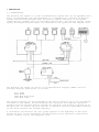
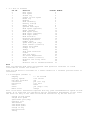
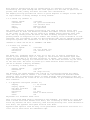
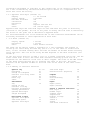
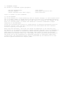
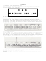
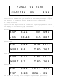
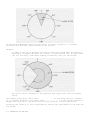
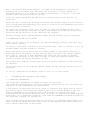
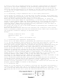
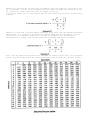
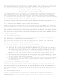
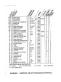
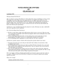
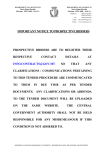
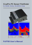
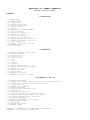
HERCULES 390 OWNERS HANDBOOK
Volume 1 Primary System
CONTENTS
1 DESCRIPTION
1.1 INTRODUCTION
1.2 PRIMARY SYSTEM
1.2.1 Computer Unit
1.2.2 Master Display Unit
1.2.3 Multifunction display
1.2.4 Analogue meters
1.2.5 Sensors
1.3 DESCRIPTION OF PRIMARY CHANNELS
1.3.1 List of Channels
1.3.2 Boatspeed (channel 1)
1.3.3 Stored log (channel 2)
1.3.4 Reset log (channel 4)
1.3.5 Battery voltage (channel 7)
1.3.6 Apparent wind speed (channel 10)
1.3.7 Apparent wind angle (channel 13)
1.3.8 Timer (channel 30)
1.3.9 Summary of available functions
1.4 EXPANDED SYSTEM
1.5 20/20 DISPLAY
2 OPERATION
2.1 OPERATION AT MASTER DISPLAY UNIT
2.1.1 Channel selection
2.1.2 Page selection
2.1.3 Trip functions
2.1.4 Trim functions
2.1.5 Reset
2.1.6 Start
2.1.7 Damping
2.1.8 Lighting
2.1.9 Use of remaining keys
2.2 OPERATING AND SElliNG THE ALARMS
2.2.1 Setting the alarms
2.2.2 Muting the alarms
2.2.3 Sector alarms
2.3 OPERATION AT THE MFD
2.4 OPERATION AT THE 20/20 DISPLAY
3 CALIBRATION & SET UP
3.1 SPEED/LOG CALIBRATION
3.1.1 Calibrating a single underwater unit or Sonic Speed installation
3.1.2 Calibrating twin underwater unit installations
3.1.3 Calibration runs
3.2 MASTHEAD UNIT CALIBRATION
3.2.1 Masthead alignment
3.2.2 Adjusting the calibration value
3.2.3 Sailing trial
3.3 MASTER DISPLAY UNIT SET-UP
3.3.1 Selecting channels for channel description
3.3.2 Adjusting PAGE display channel description
3.3.3 Adjusting CHANNEL display description
3.4 MFD CHANNEL ALLOCATION
3.5 SETTING UP A DEDICATED 20/20 DISPLAY
3.6 ANALOGUE METER SCALING
3.6.1 Boat Speed
3.6.2 Apparent wind speed
3.7 EXPANDED SYSTEM
APPENDIX 1 COMPLETE LIST OF HERCULES 390 CHANNELS
APPENDIX 2 20/20 DISPLAY CONNECTIONS
1 DESCRIPTION
1.1 INTRODUCTION
The Hercules 390 System is a yacht instrumentation system that can be expanded from a
basic log/speedometer and wind instrument to a comprehensive, accurate information
system. The following diagram shows the primary system, the heart of the system
comprising the Computer Unit and the Master Display Unit. The primary sensors (water
speed, wind speed and wind angle) are connected to the system via the Computer Unit.
The Hercules 390 system can run up to 25 multifunction displays (MEDs) and also
analogue displays (indicators) as follows:
Boat speed
Wind speed
Magnified Wind angle
3600 Wind angle
The digital displays can be programmed by the user to display any of the 32 channels
available in the system. All the displays have provision for lighting. Extensive
thought and care has been used to provide for practical and accurate calibration in
Hercules 390. To achieve the best results, calibration should be performed carefully
in the first instance and checked regularly.
A calibration record chart for your system appears at the beginning of this book
Please use this as the information recorded could be very important, particularly
should a memory loss in the equipment occur.
1.2 PRIMARY SYSTEM
1 .2.1 Computer unit
The computer unit carries out most of the data processing for the system but has no
operator controls. It accepts inputs from the underwater unit, masthead unit and
compass (if fitted) and provides outputs to the appropriate analogue indicators and
to the Master Display Unit. The supply voltage is a nominal 1 2V or 24V dc, and
ON/OFF switching is performed at the ship92s main switchboard.
1 .2.2 Master Display Unit (MDV)
This unit provides overall control of the system and uses a large vacuum fluorescent
display for data and accompanying text. A keyboard with eight keys enables the
operator to enter all the necessary information and commands to operate the system.
All the displays are in English but may subsequently be changed by the operator to
the owners requirements, to give either a different form or different language. See
para 3.3 for details.
The MDU also provides NM EA and RS232 interfacing. See Volume 4 of this manual for
details of these and the associated remote channels.
1 .2.3 Multifunction display (MFD)
Up to four separate functions can be displayed at any
consists of a moulded case with a window behind which
display (LCD). Four push button selector switches are
face of the unit to enable selection of a function to
of these units. The MFD
is a four digit liquid crystal
provided on the front
be made.
The three left hand keys are used to select the three channels which have been
allocated to the MFD. This allocation is normally made when the system is first set
up, but it may subsequently be changed if required.
The right hand key is used to select any one of the available channels at any time.
1 .2.4 Analogue meters
The primary Hercules 390 system provides for the inclusion of analogue meters for the
following functions:
APPARENT WIND SPEED 0-50 knots
APPARENT WIND ANGLE 3600
BOAT SPEED 0-12 knots (or 0-50 knots)
MAGNIFIED WIND ANGLE 40°-0-40° at bow or stern
All analogue meters used on the Hercules 390 System are of the standard B&G 4 inch
type. The readings on each are subject only to calibration and damping adjustment at
the MDU.
1.3 DESCRIPTION OF PRIMARY CHANNELS
The Hercules System 390 can provide 32 separate functions which appear in digital
code within the MDU and Computer Unit and also on the MFD databus* using time sharing
(multiplexing). Thus each function occupies a particular ‘time slot’ in the rapidly
repeated sequence. These time slots are referred to as ‘channels’ and are given
channel numbers (0-31).
The channels described in the following paragraphs are available with the primary
system. The remaining channels are described in Volumes 2 & 3 of this manual.
When RS232 and/or NMEA interfacing is employed, as described in Volume 4, an extra
set of 32 channels becomes available and these are termed ‘Remote Channels’.
*MFD databus - the cable carrying the information to the MFDs.
1 .3.1 List of channels
Vol No.
2
1
1
3
1
2
2
1
2
3
1
2
3
1
3
2
3
3
2
3
2
3
3
3
3
2
2
2
2
3
1
3
Function
Channel Number
Heel angle
0
Boat Speed
1
Stored log
2
Change of boat speed
3
Reset log
4
Heading
5
Dead reckoning
6
Battery voltage
7
Depth (feet)
8
Optimum wind angle
9
Wind speed (apparent)
10
Depth (metres)
11
Wind speed (true)
12
Wind angle (apparent)
13
Wind angle (true)
14
Wind direction
15
Reaching performance
16
Tacking performance
17
Rudder angle
18
Speed made good (Vmg)
19
Other sensors (linear 2)
20
Target boat speed
21
Change of Vmg
22
Leeway
23
True wind correction
24
Course
25
Trim tab angle
26
Sea water temperature
27
Other sensors (linear 1)
28
Distance lost along track
29
Timer
30
Distance lost to windward/leeward
31
Note
Next leg apparent wind angle and apparent wind speed are available if a Deck
Controller is fitted. See Volume 2.
Tide set and drift is available at a remote channel if a suitable position fixer is
interfaced.
1.3.2 Boatspeed (channel 1)
Damping
Display update
Raw data available
Calibration
Resolution
Units
Alarm
Meter scale
0 - 99 seconds
0.25 second
yes
yes (via log)
0.01 knot
knots
yes (high & low)
Change
Part of the basic information required from any yacht instrumentation system is Boat
Speed. It is used both for navigation and for performance measurement It also forms
the basis for many of the other calculations carried out by the 390 such as:
Change of Boat Speed
Target Boat Speed
Speed made good (Vmg)
Distance lost
Performance
True Wind Angle
True Wind Speed
Change of Vmg
Wind direction
Leeway
Boat speed is derived from the log reading which is a measure of nautical miles
travelled by the yacht through the sea. Boat Speed is not the same as speed over the
ground, when tide, leeway and drift are taken into consideration.
The damping facility provides the choice of quick response to changes in Boat Speed
in light weather or steady readings in heavy weather.
1.3.3 Stored log (channel 2)
Display update
Calibration
Resolution
Units
Damping
4 seconds
Yes (port and starboard)
0.01 nautical mile
Nautical miles
Not applicable
The output consists of distance travelled by the yacht in nautical miles. This
channel cannot be reset and therefore provides the number of miles sailed by a yacht
in the course of its life. The log reads up to 999999* before starting again from
zero. The log reading forms the basis for dead reckoning navigation and is the
primary method of navigation for all seamen. The accuracy of the calibration is most
important. The log reading is used for dead reckoning (DR) and for updating satellite
navigation systems. The calibration of the log should be checked whenever possible.
*999999 on ‘TRIP’ but 99.99 on ‘CHANNEL’ and MFDs.
1.3.4 Reset log (channel 4)
Display update
Calibration
Resolution
Reset
4 seconds
Yes (via stored log)
0.01 nautical mile
Yes
The Reset Log, sometimes known as Trip Log or Day Log, is used in preference to
stored log for measuring legs of a voyage. It can be reset and started again when
required at the MDU or at the Deck Controller if fitted. (See Volume 2). The reset
log is used when carrying out calibration runs as the timer and reset log can start
at the same time. The reset log reads up to 9999.99 miles before starting again.
(99.99 on Channel 4 display and MFDs).
1 .3.5 Battery voltage (channel 7)
Display update
4 seconds
Resolution
0.01 V
Alarm
Yes (high and low)
The Hercules 390 System measures the voltage it is receiving through the supply
cable. A simple check on Channel 7 will warn the crew whether the batteries need
charging. This is particularly useful on night passages when navigation lights can
drain the batteries. An alarm can be set on this channel to give immediate warning of
this situation.
1 .3.6 Apparent wind speed (channel 10)
Damping
0 - 99 seconds
Display update
1 second
Raw data available
Yes
Calibration
Yes
Resolution
0.1 knot
Units
Knots or metre/second
Alarm
Yes
Adjustable for different meter scale
This is the wind speed which is measured at the masthead. For example in a five knot
wind a moored boat would measure five knots, but if running at four knots downwind
would only measure one knot. Similarly, when motoring directly into afive knotwind at
four knots, the apparent wind speed would be nine knots.
Apparent wind speed is used for many of the performance calculations and relies on a
clear flow of wind across the anemometer cups.
Calibration adjustment is available on this channel but is not normally required. B&G
use a unit calibrated by the British Meteorological Centre as a comparison for all
units that leave the factory.
1.3.7 Apparent wind angle (channel 13)
Damping
Display update
Raw data available
Calibration
Resolution
Units
Alarm
0 - 99 seconds
2 seconds
Yes
Yes
0.10
Degrees from the bow
Yes (sector type)
Apparent wind angle and true wind angle are the same when the yacht is stationary
(relative to the ground). As soon as the yacht is moving the true wind is modified by
the motion of the yacht and is described as Apparent Wind.
All wind measurements are at the masthead and in some conditions measurements can be
noticeably different to those experienced at deck level.
1 .3.8 Timer (channel 30)
Display update
Resolution
Units
1 second
1 second
hours minutes seconds
The timer can be used as either a stopwatch or a race countdown. The channel is
called up for reset using the TRIP key (see 2.1.3). If the timer is started from
zero, it will continue running until 99 hours 59 minutes 59 seconds before starting
again from zero. This can be set using the MDU keyboard or the Deck Controller (see
Volume 2).
If the race start facility is used a 15,10 or 5 minute count-down can be set, and the
timer counts down to zero. The timer then continues counting up from zero as a
stopwatch for the duration of the race or until stopped. The alarm on the MDU sounds
as the timer passes through zero to indicate the start of the race. The timer
function can be repeated on MFDs so that the crew can be aware of the start countdown.
1.3.9 Summary of available functions
Speed & log
Boatspeed
Change in boatspeed
Distance lost along track
Stored log
Reset log
Timer
Performance
Vmg
Change in Vmg
Distance lost Vmg
Reaching performance
Tacking performance
Optimum Wind Angle
Target Boatspeed
Wind speed & angle
Apparent wind speed
True wind speed
Apparent wind angle
Ch. No.
01
03
29
02
04
30
19
10
12
13
True wind angle
Wind direction (magnetic)
14
15
Compass
Heading
Dead reckoning
Course
05
06
25
Depth
Depth (feet)
Depth (metres)
08
11
Sensor & computer functions
Heel angle
Rudder angle
Trimtab angle
Temperature
Battery voltage
Linear 1
Linear 2
Leeway
True wind correction
00
18
26
27
07
28
20
23
24
1.3 EXPANDED SYSTEM
For details of expanded system equipment:
Hercules Depthsounder
Halcyon Compass
Sensor Interface Unit (Heel angle)
Sonic Speed
Mast angle correction unit
Deck Controller
refer to Volume 2 of this handbook
1.4 20/20 DISPLAY
The 20/20 Display is a high visibility form of digital display. It uses figures which
are 1.5 inches (40mm) in height which can easily be read at a considerable distance.
The 20/20 display can be mounted on the sight line at a position, for example on the
mast of a sailing yacht, to enable the functions of several individual cockpit
repeaters to be performed.
20/20s are available with yellow or orange digits to identify information from the
different sources. They are fully sealed from the environment and have internal
electric lighting for night use.
When used with Hercules, the 20/20 can either be dedicated to one function (say
boatspeed) or can include an optional cockpit selector key which allows selection of
any one of the channels of information which Hercules produces. Thus, for example,
when racing it may initially show count-down, then course to steer followed by
performance and finally time to go. Any number of 20/20s may be driven by Hercules
and these can be any combination of dedicated displays or selectable types with
cockpit keys. The information being read is identified by an indicator as on the
Hercules system multifunction display (MFD).
2 OPERATION
1.5 OPERATION AT THE MASTER DISPLAY UNIT
When the Hercules 390 System is switched on at the ship’s main switchboard the
following display occurs at the MDU.
B & G
HERCULES
390
/01
At the bottom right hand is the software program version number.
When operating the MDU keyboard it should be borne in mind that the functions
indicated above the keys are selected by pressing the appropriate key. The functions
printed below the keypad, however, are SH I FT functions and therefore require
the operation of the SHIFT (left-hand) key before pressing the required key. It is
not necessary to hold down the shift key to obtain a ‘SHIFT’ function, merely press
it before the required key.
2.1 .1 Channel selection
Use the CHANNEL key to select an individual channel for display at the Master Display
Unit. Press the key and the last function obtained by this key will be displayed.
Press the key a second time and keep it pressed. The channel number for the function
will be displayed and immediately will start to count up or down depending upon which
way the indicator, at the bottom left of the display, is pointing.
To change the direction of the count in order to reach the required channel more
quickly, release the key and press it again.
The arrow will point in the other direction and the direction of the count will be
reversed.
FUNCTION NAME
CHANNEL
01
4.11
An automatic channel selection facility is available and is accessed by pressing SHI
FT followed by CHANNEL/AUTO. The channels are displayed in sequence. When the
required channel is on view operate CHANNEL! AUTO to stop the sequencing. To reverse
the direction of sequencing operate SHIFT followed by CHANNEL/AUTO.
2.1.2 Page selection
Operate the PAGE key to select one of the four pages of programmable data for
display. Each page has four channels, and successive operations of the PAGE key cause
the display to show the four pages in sequence.
Navigation
B.SP
5.21
HD
090
LOG
39.49
D.R. 087
Apparent wind
B.SP
5.21
W.SPA 8.4
AWA 123TWD
267
True wind
B.SP
5.21
W.SPT 5.2
tWA 123TWD
268
199
Performance
B.SP
5.21
PERT
T.SP
5.18
OWA - 01
The content of each page can be changed if required (see para 3.3.1).
2.1.3 Trip functions
Successive operations of the TRIP key cause the following channels to be displayed:
Timer
Stored Log
Reset Log
Dead Reckoning
(channel
(channel
(channel
(channel
00)
02)*
04)
06)
The function on display may be reset by pressing the RESET key. When Timer is being
displayed, successive operations of the RESET key cause the reset value to cycle
through:
0 minutes
5 minutes
10 minutes
15 minutes
Pressing the START/CAL key starts all the functions which have been reset provided
that the timer is not currently counting down.** Pressing the START/CAL key a second
time stops the displayed function. The display indicates whether the function is
reset (RE), frozen (FR)
or running (RU).
* Though Stored Log cannot be reset it is included under Trip so that the ‘frozen’
facility may be used.
Frozen (FR) - this means that the display is stopped but the function is still
running. The display ‘catches up’ when ‘START’ is pressed again.
** When the timer is counting down, if the Reset Log and DR functions are reset, they
will automatically start when the timer reaches zero. Under these conditions it is
not possible to start these functions using the Start key either at the MDU or Deck
Controller. If Reset Log and/or DR are not reset during the ‘count-down’, they will
be unaffected by the Timer.
These functions can also be performed using the Deck Controller if fitted. (See
Volume 2 of this manual).
2.1.4 Trim functions
Operating TRIM causes the Trim channels to be displayed.
Channel
Channel
Channel
Channel
03
22
29
31
(change of boat speed)
(change of Vmg)
(distance lost along track)
(distance lost to windward)
For details of these channels refer to Volume 3 of this manual.
2.1.5 Reset
This key is used to reset (set to zero) all functions with this facility. ‘Trim’
functions restart without any further keystrokes but other functions require the use
of ‘START’.
For further details refer to Volume 3 of this manual.
2.1.6 Start
‘Trip’ functions (as listed in para 2.1.3) which have been reset are started when
this key is operated.
2.1.7 Damping
Variable damping is provided on four channels:
Channel
Channel
Channel
Channel
01
13
10
05
Boat speed
Apparent wind angle
Apparent wind speed
Heading
Display the required channel at the MDU using the CHANNEL key. Then operate SH FT
followed by PAGE/DAMPING. The existing damping setting is now displayed. Press RESET
until the first character to be changed flashes. Release RESET and adjust the
character using the START/CAL key. When the required character appears, release
START/CAL and set the character in by pressing RESET. The next character then starts
flashing. Repeat the procedure until no characters remain flashing. Operate CHANNEL
to return to the data display. Damping adjustment is also available for Tide on a
remote channel. See Volume 2.
2.1.8. Lighting
When data is being displayed either through use of the CHANNEL key or PAGE, the right
hand key is available to control the MDU display illumination. Successive operations
of this key cause the lighting level to cycle through the available values The
illumination remainsat the selected level until next altered by means of the lighting
key. Note that MFDs and analogue indicators will be on a separate lighting control.
2.1.9 Use of remaining keys
Keys I/01 and I/02 are used in relation to interfacing with external instruments and
details are provided in Volume 4 of the manual.
Key CAL is used in relation to calibration and details are provided in Section 3 of
this handbook
2.2 OPERATING AND SETTING THE ALARMS
The MDU provides the following alarms:
Boat speed High
Boat speed Low
Apparent wind speed High
Apparent wind speed Low
Battery voltage High
Battery voltage Low
Apparent wind angle Sector
Heading Sector*
*Refer to Volume 2 of this manual.
Pressing the ALARM key steps the display through all the alarm settings starting with
the last active alarm. The display shows the channel text, alarm value and status.
There are three types of alarm: high, low and sector.
HIGH
sounds when the measured value is larger than the alarm value. The
internal alarm sounds:
LOW
sounds whenever the measured value is less than the alarm value.
The internal alarm sounds:
SECTOR
sounds when the measured value is within an alarm sector defined by
the clockwise and anti-clockwise values.
When an alarm is active it may be temporarily stopped from sounding (muted). This is
described in para 2.2.2.
All the alarms may be switched off completely by pressing SHIFT and then ALL OFF, but
they can only be switched on again by following the procedure described in para 2.2.1
for each alarm individually.
Should one of the alarms sound but then de-activate before the user can determine
which alarm has sounded, the last alarm to
have sounded is displayed by pressing the ALARM key once.
2.2.1 Setting the alarms
(a)
Display the alarm setting by pressing the ALARM key. The last alarm to have
sounded is displayed. To change to another alarm press ALARM again until the
required alarm is displayed. Note that separate displays are provided for low
and high alarms of the same function. For APPARENT WIND ANGLE the alarm sounds
within an alarm sector. The two values defining this sector appear on the same
display.
Refer to 2.2.3 for further information on sector alarms.
(b)
Change the alarm value if required by pressing the RESET key and holding it
down until an asterisk (*) appears and flashes at the first digit of the alarm
value. This should happen after around 1.5 seconds. Operate START to cycle
through the available digits and then press RESET to fix that value and move
the flashing asterisk to the next digit. When all three digits have been
adjusted press RESET to complete the setting.
(C)
Switch the alarm on or off by pressing START. Successive operations of START
cause the alarm to switch on and off alternately. The word 91ON92 or 91OFF92
appears at the bottom right hand side of the display.
2.2.2 Muting the alarms
It is sometimes necessary to stop an alarm from sounding whilst active (in an alarm
condition) without switching it off. This is termed ‘muting the alarm’. To do this
press ALARM (if the display is not already in the alarm mode) and then RESET
while the alarm is sounding.
Under these circumstances, a visual indication of the alarm is obtained. The alarm
settings will be displayed as in 2.2.1 (a) but the display at the bottom right will
read 91ACT92 indicating that the alarm is active. Additionally the function
description and ‘ACT’ flash on and off. Muting the alarm does not prevent the audible
alarm from sounding again should another alarm condition be experienced.
2.2.3 Sector alarms
There are two sector alarms in the Hercules 390 system: Apparent WIND ANGLE which is
considered here and HEADING which is discussed in Volume 2.
The alarm will sound in the sector created by the two alarm values set by the user.
The alarm sector created is between the first value and the second value moving in a
clockwise direction from the first to the second. The clockwise direction is as
imagined when looking down in plan view.
It should be noted that apparent wind angle is given in degrees either side of the
bow from 0º to 179º on the starboard side and
from 0º to -180º on the port side. The alarm settings must therefore follow this
convention.
Example
To set up the apparent wind angle alarm so that it sounds in the shaded area of
the figure below, le 200 either side of ‘head to wind’, an apparent wind angle
of -020º must be entered at the bottom left hand side of the display
(having displayed the apparent wind angle alarm setting as described in para
2.2.1 (a). Then an angle of +020º should be entered at the bottom right hand
side of the display.
It should be remembered that the alarm sector is always created in a clockwise
direction from the first angle entered to the second.
Example:
In order to set up an apparent wind angle alarm that sounds when the apparent
wind angle is either less than 40º on Port, or greater than 145º on Port, enter
-40º for the first (left hand) setting followed by -145º for the second.
The alarm will be activated if the apparent wind angle moves into the shaded
sector.
The audible alarm gives short tones . . . . . . if the alarm sector is entered
in a clockwise direction, but longer tones - - - - - - if the reverse applies. A
change over from one to the other occurs at the mid point of the alarm sector.
Switching the alarm on or off is performed in exactly the same manner as for high and
low alarms.
2.3 OPERATION AT THE MFD
Any of the three preselected channels at an MED can be displayed at any time by
pressing one of the three left hand keys. The allocation of these channels is
described in para 3.4. To display any other function refer to section 1.3 for the
channel number and then proceed as follows:
Press the right hand SELECT key and the last function used on this key will be
displayed.
Press the key a second time and keep it pressed. The channel number for the function
will be displayed and immediately will start to count up or down depending upon which
way the pointer is showing.
To change the direction of the count in order to reach the required channel more
quickly, release the key and press it again. The pointer will indicate in the other
direction and the direction of the count will be reversed.
Release the key at the required channel number and the function will be displayed.
2.4 OPERATION AT THE 20/20 DISPLAY
There are two types of 20/20 display: the dedicated display and the selectable type
with operator control.
To display a particular function on the selectable type, refer to section 1.3 for the
channel number and then proceed as follows:
Press the remote control button and the channel number of the present function is
displayed. Press the button a second time and keep it pressed. The channel numbers
will start to count up or down depending upon which way the pointer is showing.
To change the direction of the count in order to reach the required channel more
quickly, release the button and press it again.
The pointer will indicate in the other direction and the direction of the count will
be reversed.
Release the button at the required channel number and the selected function will be
displayed.
To set up a dedicated 20/20 Display refer to para 3.5 of this Volume.
3
CALIBRATION AND SETTING UP THE SYSTEM
3.1 SPEED/LOG CALIBRATION
One calibration adjustment is needed for these two functions.
The system has been designed to provide separate calibration for port and starboard
impellers of twin underwater unit installations.
A calculation is performed every half second to determine boat speed and log values.
For each of these calculations the computer unit has to decide whether to use the
PORT or STARBOARD log calibration value. The decision is based on heel angle
information from the Sensor Interface Unit, if fitted, or otherwise from the apparent
wind angle. It is important, therefore, that PORT and STARBOARD calibration values be
the same when carrying out calibration.
This is particularly significant when log calibration is performed under power, when
small variations around zero heel angle occur or the apparent wind angle varies by a
small amount either side of dead ahead.
A series of runs over a measured distance is required. Three methods are described
and a choice can be made depending on the prevailing conditions and the accuracy
required. In each case a correction factor k is calculated. This is the amount by
which the indicated reading has to be divided to give the correct reading; i.e. if k
= 1.03 the log is under-reading and so the present calibration value in Hz/knot is
divided by 1.03.
3.1.1 Calibrating a single underwater unit or Sonic Speed installation.
Select Stored Log (channel 02) at the MDU using the CHAN N EL key. Press SHIFT then
CAL to display port calibration value. Note the value (6.20 Hz/Knot factory setting).
Select starboard by pressing SHIFT again followed by CAL.
Enter the value noted from the port display if it is different. To adjust the
calibration value press RESET for approximately 1.5 seconds until the first number
starts to flash. Release RESET and operate START/CAL to cycle through the available
numbers. Press RESET to step to the next digit and repeat the procedure for the
remaining digits. RESET must be pressed following adjustment of the last digit as
this enters the new value into the program.
Now select and carry out one of the three methods of performing the calibration run
as described in para 3.1.3.
When the correction factor 91k92 has been obtained, the calibration value already
noted is divided by 91k92to give the new calibration value. Enter this in both port
and starboard calibration displays as described above.
Example:
Starting calibration value
6.20
Correction factor ‘k’
1.03
6.2
1.03 = 6.02
Value to be entered: 6.02
3.1 .2 Calibrating twin underwater installations
Select one of the three methods of performing the calibration run given in para
3.1.3. Set the changeover switch manually to select the port impeller. Carry out the
calibration runs as instructed and obtain the port correction factor k (p).
Note this factor and then repeat the calibration runs with the changeover switch set
to select the starboard impeller. Calculate the starboard correction factor k (5).
Return the changeover switch to AUTO after completion of the calibration runs.
Select Stored Log (channel 02) at the MDU using the CHANNEL key. Press SHIFT then
START/CAL to display port calibration value. Note the value (6.20 Hz/Knot factory
setting). Divide this value by the port correction factor k(p). Enter the
new calibration value by pressing RESET for approximately 1.5 seconds until the first
number starts to flash. Release RESET and operate START/CAL to cycle through the
available numbers. Press RESET to step to the next digit and repeat the
procedure for the remaining digits. RESET must be pressed following adjustment of the
last digit as this enters the new value into the program.
Select starboard by pressing SHIFT again followed by START/CAL Note the starboard
calibration value. Divide this by the starboard correction factor k(s) and enter the
new calibration value using the same method as for port. RESET must be
pressed following adjustment of the last digit as this enters the new value into the
program. Operate CHANNEL to return to data display.
3.1.3 Calibration runs
Method ‘A’ is the simplest as no timing is involved, but the vessel
constant speed for both runs, and it is assumed that the current is
out a run in both directions and note the distance indicated by the
beginning and end of each run to give the indicated distance run in
D2.
must maintain a
constant. Carry
log at the
each case: Di and
Method B is carried out as above but in addition the time taken for each run ti and
t2 is recorded. In this case the speed need not remain constant and calibration can
be carried out under conditions when the speed could vary,
e.g. whilst under sail or when engine rpm are maintained but the boat is affected by
windage.
Method C is the most accurate method requiring three runs over the measured distance.
Again there is no necessity to maintain constant speed and the calibration can be
carried out, if required, under sail. Current is assumed to be increasing or
decreasing at a steady rate. Record times and indicated distances as before.
Note: for the above calculations M is measured in nautical miles and t is in decimal
hours. (See following table for converting minutes and seconds into decimal hours).
3.2 MASTHEAD UNIT CALIBRATION
3.2.1 Masthead alignment
The masthead unit can be mounted with the spar pointing in anyconvenient direction so
that it is free from obstruction. Following installation of the masthead unit it may
be necessary to compensate for the angle of the spar from the fore-and-aft line. If
the spar is displaced from the fore-and-aft line by a substantial amount, an estimate
of the angle should be made initially. This is the angle from the bow moving anticlockwise when imagined in plan view. The estimated angle should be entered as
described below before carrying out sailing trials.
3.2.2 Adjusting the calibration value
Display Wind Angle (channel 13) at the Master Display Unit using the CHAN NEL key.
Then operate SHIFT followed by START/CAL. The existing value is now displayed. Use
the RESET and START keys to change the value as required. Operate CHANNEL to return
the display to Wind Angle.
3.2.3 Sailing trial
Error can be resolved by sailing alternately close-hauled on each tack If the reading
on the starboard tack is greater than port, the difference should be halved and, must
be subtracted from the masthead unit alignment reading.
If the reading on the port track is the greater, again the difference should be
halved and the result added to the masthead unit alignment reading. If the resultant
angle is less than zero (negative), add 360º and use this figure, e.g. for -1º use
359º
3.3 MASTER DISPLAY UNIT SET-UP
3.3.1 Selecting channels for page display
All four pages are allocated with channels at the factory, but they may be changed to
show any combination of channels as required. To re-allocate channels on a page first
displaythe relevant page by pressing the PAGE key as described in para 2.1.2. Press
SHIFT followed by START/CAL to display (for example) the following:
CHOl
CHOS
RElO
CH25
Press the RESET key and hold it down until the top left hand channel number starts
flashing (approximately 1.5 seconds).
Operate the START/CAL key (or hold it down*) to change the channel numbers through
those available, including any remote** channels that have been incorporated. When
the required channel number is obtained operate RESET to set in the
new channel number and to cause the next channel number to flash. When the required
channels have been allocated, press PAGE to exit from the adjust mode and display the
description and data for the selected channels.
* Holding down the START/CAL key causes the display to cycle through the channel
numbers including any remote channels. To change the direction of cycling release
START/CAL and press it again.
**Remote refers to a function from an external computer or NM EA position fixer on an
MFD display. Refer to volume 4 para 2.2 for details.
3.3.2 Adjusting the PAGE display channel descriptions
Display the page on which text is to be changed using the PAGE key. Press and hold
down RESET until the top left-hand character flashes (approximately 1.5 seconds).
Press START/CAL and hold it down to cause the adjustable characters to cycle through
the available numbers/letters including decimal point and blank Note that the decimal
point occurs in sequence between ‘A’ and ‘9’, and the blank between ‘Z’ and ‘0’.
Releasing START/CAL and holding it down again reverses the direction of cycling. When
the required character is on display, operate RESET to set the new text and to move
to the next adjustable character. Press PAGE to exit from the adjust mode.
A B C D E F G H I J K L M N 0 P Q R
S T U V W X Y Z
0 1 2 3 4 5 6 7 8 9
If a decimal point is to be inserted, cycle through the available characters using
the START/CAL key until the decimal point appears. Then press RESET. The decimal
point is entered but the same character will continue to flash, awaiting amendment
or confirmation with another press of RESET. (Note: a decimal point cannot be entered
alone. Another character has to be entered as well).
To remove a decimal point which has just been inserted use RESET and make the
character with the decimal point flash. Press RESET and the decimal point is removed.
3.3.3 Adjusting the CHANNEL display channel descriptions
Display the channel on which text is to be changed using the CHANNEL key. Press and
hold down RESET until the top left-hand character flashes(approximately 1.5 seconds).
Press START/CAL and hold it down to cause the adjustable characters to cycle
the available numbers/letters. Releasing START/CAL and holding it down again
the direction of cycling. When the required character is on display, operate
set the new text and to move to the next adjustable character. Press CHANNEL
from the adjust mode.
through
reverses
RESET to
to exit
3.4 MFD CHANNEL ALLOCATION
The MFD Mk2 is not opened when allocating the channels. It remains factory-sealed.
The setting up is done using the front keyboard.
The three left hand keys can be used for displaying any channel. The right hand
button can only be used for the Select function.
To allocate a channel to one of the three left hand keys:
(1) Press the key once so that the display shows channel data.
(2) Press the key a second time AND KEEP IT PRESSED for ten seconds. The display
will show the channel number for that function. A small pointer at the left of
the display will point up or down to indicate whether the numbers will count
up or down. Repressing the key will reverse the direction of count (and the
pointer) so that the quickest count to the required channel number can be
made.
(3) After the key has been pressed for ten seconds, the channel number will start
to count up or down as decided above. Release the key when the channel number
for the required function is displayed.
(4) The new function is now selected and the appropriate labels should be inserted
by springing out the label frame, removing the old label, inserting the new
one and replacing.
3.5 SETTING UP A DEDICATED 20/20 DISPLAY
Connect the display as shown in the connection diagram, but leave the violet wire
disconnected with the end bared. With the system operating, touch the bared end to
the blue terminal at the junction box to step the display through the channels. When
the required channel is reached, the 20/20 is set up and the violet wire may be cut
back.
3.6 ANALOGUE METER SCALING
Should an analogue meter be fitted with a maximum scale indication different to
standard, the following procedure should be followed in order that the meter will
read correctly.
3.6.1 Boat Speed
1
2
3
Select Boatspeed at the MDU
Operate SHIFT then CAL to present the existing meter scaling (maximum dial
reading). The factory setting is 12.5 knots to suit the 12.5 knot indicator.
Use the same technique as for other calibration changes to set and enter the
new value using the RESET and START/CAL keys.
3.6.2 Apparent Wind Speed
1
2
3
Select Apparent Windspeed at the MDU
Operate SHIFT then CAL three times to present the existing meter scaling
(factory setting is 50 knots).
Use the same technique as for other calibration changes to enter and set the
new value using the RESET and START/CAL keys.
3.7 EXPANDED SYSTEM