1
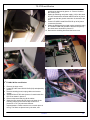
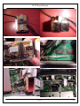
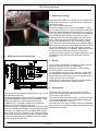
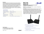
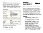
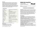
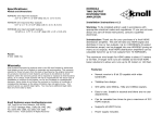
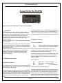
TS-870S modification A new life for the TS-870S by Andrea Weick hb9fbd and Tiziano Christen hb9blq 1. Introduction The TS-870S is still a good rig for its 6 years old lifetime. Its advanced features include dsp filtering and demodulation, antenna tuner, keyer, complete remote controlling and more. But under some circumstances intermediate stages get overloaded showing some intermodulation behaviour. These signals cannot be repaired by the processing of a dsp … Nobody is perfect ! Here the reader will learn how this annoying drawback can be really improved. To build a cut frequency of +/- 300 Hz (600 Hz bandwidth) the injected signals in the mixers have to be shifted of about +/1200 Hz. The right shift is calculated by the microprocessor and generated by the DDS. These details are described in [4]. TS-870S filter selection The concerned filters are : I remember the first time I asked Tiziano if he was interested in a new modification for the TS-870S. We were participating at the Helvetia contest and experienced overloading at the IF stage and dsp section. I already had some modification information by k3bu Yuri and UT1IA Vladimir [1], but I needed additional selectivity for intensive CW operation. The planned solution should integrate a smart way to switch between filters without external components. - XF2 CF452 3 Khz at 8.83Mhz and 600 Ohms impedance 3 Khz at 455 Khz and 2 KOhms impedance These elements behaviour quite well during normal conditions, but under strength conditions lead to stages overloading due to the inadequate selection. The proposed solution replaces the existent filters with better ones. The improved filters are produced by International Radio Corporation [3] and matched for Kenwood radio TS850 and TS-830. 2. Modification description Here some data : - TS-870S filter principle #94 #98 #96 8830.0 Khz, 8830.7 Khz, 455.0 Khz, 2.1 Khz bandwidth 400 Hz bandwidth 2.1 Khz bandwidth The TS-870S uses two filters of 3 Khz for CW as well for SSB filtering below 2.6 Khz : one for the second IF at 8.83Mhz and All the filters have symmetric behaviour. one at the third IF at 455 Khz. How can two filters of 3 Khz be used to set a CW bandwidth of 600 Hz ? Both the bandwidth and the work frequency of the filters are fixed. If we make the first filter working on the hi-cut slope tune and the second filter on the low-cut slope tune, the sum of this selection will be the same as a unique 600 Hz filter. The reader is pleased to pay attention to the frequency cut of filter #98 : 8830.7 Khz. The filter is cut for 700 Hz away from the IF frequency. This could lead the operator to assume it doesn’t work, but it does. A filter cut to 8830 Khz would not properly work, because the microprocessor shifts the received signal somewhere near the cut frequency of the 3 Khz filter (- 1/1/2012 1/6 TS-870S modification /+ 1500 Hz). Installing a filter with the exact cut frequency of the IF would filter a part of band (window) without ham signals. The overall modification was evaluated as easy also because no special equipment is required. The implementation is split in 2 parts : rd insertion of the 2.1 Khz filter in the 3 IF (455 Khz). nd insertion of the switching unit at the 2 IF (8.83 Mhz) for 2.1 Khz and 400 Hz filters. Some advices before starting : use caution when handling electronic boards and elements suffering from static charge. Be careful when dissoldering existing filters. rd Figure 2 3 IF SSB filter modification 1. Remove the upper cover. 2. Locate FINAL UNIT board X45-351x-xx (C/5) near the loudspeaker as depicted by picture 1. 3. Unplug cables and remove screws. 4. Substitute filter XF2 with 2 piece of coaxial cable like RG174 as shown in picture 2. 5. Remount the board and plug all the cables. 6. Place the new filter #96 nearby the loudspeaker as shown in picture 3 and 4. For dimension comparison the reader sees the old filter on the loudspeaker. Fix the filter to the chassis as shown in picture 5 and solder the coaxial cable to the filter as shown in figure 6. 7. Remount the upper cover. Figure 3 Figure 1 Figure 4 1/1/2012 2/6 TS-870S modification 7. 8. 9. 10. positioned as depicted by picture 11. Picture 12 shows the circuit by side. Solder the switching unit power supply (12V) to the same RF UNIT board with a shielded cable as shown in picture 13 and note that the ground connection is screwed to the print. Locate LCD ASSY board B38-0736-05 up left of picture 14 near the flat cable. Solder the DIM signal (the signal used to switch the relay) to a shielded cable and ground the shield to the print by the same screw as shown in picture 15. Remount the shielding board and the lower cover. Figure 5 Figure 7 Figure 6 nd 2 IF SSB/CW filter modification 1. Remove the lower cover. 2. Locate RF UNIT board X44-3210-00 (A/9) as depicted by picture 7. 3. Remove shielding board, unplug cables and remove screws. 4. Substitute filter CF452 with 2 pieces of coaxial cable like RG174 as shown in picture 8. 5. Remount the board and plug all the cables. 6. Solder the filter input/output of the circuit shown in the Figure 8 following chapter to the coaxial cable as shown in pictures 9 or 10. They show two different implementations. Please note there is not much place in the rig. The filters are placed one by the other, and 1/1/2012 3/6 TS-870S modification Figure 9 Figure 12 Figure 10 Figure 13 Figure 11 Figure 14 1/1/2012 4/6 TS-870S modification 4. Operation proceeding Operating mode in SSB do not change, but note that the new 2.1Khz filter is selected only if the DSP high cut frequency is lower than 2.6 Khz. CW must be handled differently. Personally I assigned menu number 50 (DIMMER – Light of the front panel) directly to one of the four programmable front panel keys. By pressing the preset key the user will select the IF filter by pushing up/low keys. The confirms of the setting is seen through the grade of light on the LCD front panel. Another solution is to insert menu number 50 into the quick menu ; details are given in the TS-870S instruction manual. Receiving CW with the 400 Hz filter is achieved by setting CW-R and will not affect transmitting mode. Selecting 400Hz filter permit to get very clean signals with DSP filter set to 400 Hz. Tuning a signal with a narrower DSP filter (for instance 200Hz) will not succeed. The installed IF 400Hz filter is cut for a frequency about 100Hz away of the IF frequency the operator is currently reading. If the operator really want to use narrower DSP filter, then the 2.1Khz SSB filter should be reselected. Figure 15 3. Switching unit and electrical schema 5. Results 1 2 3 4 5 6 7 8 9 18 17 16 15 14 13 12 11 10 8 4 1 4 1 10 1 3 5 8 10 1 3 5 3 2 3 2 As the operator switches the TS-870S on for SSB receiving, signals are clearer and gain in understanding. Setting the receiver for CW (remember – mode is CW-R) gives the operator a new dimension. To understand the meaning of this experience, set the DSP filter bandwidth to 1Khz and move around in the band. The band is almost quiet, but in the moment the operator tunes a station, will copy a very clean signal. At the time of this writing, the modification was successfully implemented in 4 transceivers, without problems. 6. Improvements The electrical schema describes how the filters on the second IF (8.83Mhz) are switched. The input signal used to switch the selectivity is taken by the signal DIM (DIMMER) located on the LCD ASSEMBLY (B380736-05) at capacitor C3. After being buffered by the ULN2803A (IC1), the signal is applied to both paralleled relays (RL1-2) and connected to Vdd (12V). Note that the buffer IC integrates the discharge diodes for the relay coils and that each darlington can provide up to 500 mA continuous. The relays used are small signal SPDT (Single Pole, Double Through) functioning at 12V. The power supply for the switching circuit is taken by a point of measure located on the same board where the 8.83Mhz IF filters are located, the RF Unit (X44-3210-00, A/9). The project could be further improved if both IF and filter frequencies could be aligned eliminating the need to receive CW in reverse mode (CW-R). This could be done in two ways at least : by having an IF filter cut to the actual shifted IF or by recalibrating the transceiver to the slightly shifted filter frequency. The reader may note I did not mention transceiver calibration. This operation could be done by experienced technicians with professional instruments. 1/1/2012 5/6 TS-870S modification 7. Conclusion This project was developed to give to TS-870S operators the ability to get cleaner signals from a rig still on the edge. The modification overall cost is not cheap, but good IF selectivity always needs good IF filters in new rigs too. I please any amateur radio who will implement this modification and have advice or tips, let me know at [2]. Finally, a heap of thanks to the people who supported me in this project: Tiziano hb9blq, George W2VJN, … 8. Annex [1] Link to a TS-870S modification site : www.mods.dk [2] Authors e-mails : [email protected], [3] International Radio Corporation, 13620 Tyee Road, Umpqua, Oregon 97486, USA. e-mail : www.inrad.net [4] HF Transceiver Kenwood TS-870S Service Manual 1/1/2012 Andrea Weick, hb9fbd Via Collina 13 6516 Cugnasco Switzerland - Europe e-mail : [email protected] 6/6