1
Internal traineeship
Automation of VW transmission 02k-DNZ
DCT Report number 21
Date: 05-04-2004
Author: A.J.Baeten
Supervisor: dr. ir. R.M. van Druten
Index
Index ................................................................................................................................................ 2
1 Introduction............................................................................................................................... 3
2 Choosing an actuation system ................................................................................................. 4
2.1 Performance ....................................................................................................................... 4
2.2 Comfort ............................................................................................................................... 5
2.3 Cost .................................................................................................................................... 5
2.4 Packaging ........................................................................................................................... 5
2.5 Conclusion .......................................................................................................................... 6
3 Opel Corsa – Easytronic .......................................................................................................... 7
3.1 Reason for automation ....................................................................................................... 7
3.2 Implemented modifications................................................................................................. 7
3.2.1
Shift and selector actuator ......................................................................................... 9
3.2.2
Actuation lay-out ...................................................................................................... 10
3.2.3
Clutch actuator......................................................................................................... 11
3.2.4
Easytronic control signal .......................................................................................... 11
4 Transmission 02k-DNZ overview ........................................................................................... 13
4.1 Transmission lay-out ........................................................................................................ 13
4.2 Properties of the synchromeshes ..................................................................................... 15
5 Required specifications .......................................................................................................... 16
5.1 Time available .................................................................................................................. 16
5.2 Finding the most critical shifts .......................................................................................... 16
6 Reduction of moments of inertia............................................................................................. 17
6.1 Calculation of the inertia’s ................................................................................................ 17
6.2 Determining the relative angular velocities....................................................................... 17
6.3 Lumping the inertia’s ........................................................................................................ 18
7 Calculating if the solution will work......................................................................................... 19
7.1 Simplifications and assumptions ...................................................................................... 19
7.2 Required synchronization force ........................................................................................ 19
7.3 Properties of the actuating system ................................................................................... 22
7.4 Synchroniser performance limits ...................................................................................... 24
8 Interpretation of the results..................................................................................................... 27
9 Conclusions and recommendations ....................................................................................... 29
9.1 Conclusions ...................................................................................................................... 29
9.2 Recommendations............................................................................................................ 29
10
Bibliography ...................................................................................................................... 30
Appendix A. ................................................................................................................................... 31
Appendix B. ................................................................................................................................... 33
Appendix C. ................................................................................................................................... 34
Appendix D. ................................................................................................................................... 37
Appendix E. ................................................................................................................................... 40
Appendix F..................................................................................................................................... 43
Appendix G. ................................................................................................................................... 44
Appendix H. ................................................................................................................................... 47
Appendix I...................................................................................................................................... 48
2
1 Introduction
This report regards my internal traineeship, the goal of the report is to look at the possibilities for
automation of a manual transmission from Volkswagen, indicated by VW02k-DNZ. In this report
will be studied if existing systems for automating a manual transmission are applicable to the
Volkswagen gearbox. These systems are implemented in, for example the Alfa Romeo 147 and
BMW M3, but also in rather small cars like the Opel Corsa and the Citroen C3. These existing
systems will be examined and then one system will be chosen based on the following criteria;
performance, cost and complexity. Because of the length of the report only the specific details of
the chosen system will be included.
Then the specifications the gearbox has to comply with are presented and in the following
chapters the shift time of the gearbox will be estimated. In the following chapters the performance
of the gearbox and actuating systems will be determined by solving the torque equilibrium on the
gearbox masses. Finally the performance of the gearbox and the actuation system will be
compared with the desired specifications and some conclusions and recommendations will be
made.
3
2 Choosing an actuation system
Now one of the before mentioned systems will be chosen, based on the following criteria:
•
•
•
•
2.1
Performance
Comfort
Cost
Packaging
Performance
The performance of a system is represented by its shift times. The faster a system can shift, the
better its performance. However manufacturers are always vague under which conditions the
given shift times are valid. This makes it difficult to predict how they will perform in a different
gearbox and different conditions, which can be less favorable. The following table with shift times
is therefore no more than a rough indication
Gearbox (car)
Min. shift time
BMW SMG II (M3 E46)
80 ms
Ferrari F1 (Maserati 4200GT)
80 ms
Ferrari F1 (360 F1)
150 ms
Ferrari F1 (Enzo)
150 ms
Bugatti Veyron (proposed)
200 ms
Ferrari F1 (575M)
220 ms
BMW SMG (M3 E36)
220 ms
Aston Martin Vanquish
250 ms
BMW SSG (3-series)
Alfa Selespeed (156 Selespeed) (old)
250ms (150ms for 1st to 2nd)
700 ms
Table 1: Shift times specified by manufacturer
In this table only hydraulically actuated systems are shown. In the following figure a comparison
concerning an unknown hydraulically operated gearbox and the electromechanically operated
gearbox “Easytronic” from Opel.
4
Figure 1: Shift time comparison hydraulic versus electromechanical
According to Figure 1, the electromechanical actuated systems are slower than the hydraulically
actuated ones. The source of this picture doesn’t mentions which hydraulic system is used in this
comparison.
It can be concluded that for performance a hydraulic system is preferred and looking at Table 1
the fastest system is the SMG II implemented in the BMW, or the one the Ferrari F1 implemented
in the Maserati 4200 GT. These systems are obviously shift the quickest.
2.2
Comfort
This is a very subjective parameter, but nevertheless it cannot be ignored. Since I have not been
able to test myself, I have based my conclusions on the available information, which was
sometimes provided by the manufacturer.
The BMW SMG II system, which had the best performance as we have seen, is also very
uncomfortable. Due to the fast gear changes, the torque is not decreased gradually, but it is
suddenly interrupted. This can be recognized by an excessive nodding movement of the heads of
the people in the car and it is not comfortable.
Looking at Figure 1 again, we can see that especially the decrease of the transmitted torque is
essential in the determination if the gear shift is experienced as comfortable. However if a
gearshift takes too long, the driver experiences it as irresponsive and annoying. All of the
automated manual gearboxes mentioned earlier have different characteristics varying from a
sportive program to a comfortable or normal shift program. From Figure 5 we can see that an
electromechanical actuated system shifts fast enough to comply with a comfortable gear change.
2.3
Cost
The used components in the automated manual gearboxes especially determine the price of such
a system. The disadvantage of a hydraulic system is that it has quite a lot of components
compared to an electromechanical one.
2.4
Packaging
5
Figure 2: Left; shift and selector actuator, Right; clutch actuator
There are only two modules that have to be added to the gearbox and they are shown in Figure
2. These modules contain all the needed sensors, actuators and even the control unit, which is
integrated with the clutch actuator as shown right in the figure above. All sensors which are not
integrated in these modules but are required for the controls are already present in a manual
gearbox. The control unit needs some of the signals from these standard sensors, so the control
unit will have to be able to receive data from them.
2.5
Conclusion
An electromechanically actuated system is preferred mainly because its low cost and its
compactness. It is also simple because it is a completely dry system, it cannot leak and
eliminates difficult sealing problems.
Another reason for choosing the Easytronic system is that it is well documented compared to the
Sensodrive solution of Citroen-Getrag, which is a comparable solution. A possible explanation
why information concerning the Sensodrive system is rather scarce is that it is introduced
recently, whereas the Easytronic system was introduced in 2000.
6
3 Opel Corsa – Easytronic
3.1
Reason for automation
Opel automated a manual transmission of the Corsa because they wanted to offer their
costumers an extra bit of comfort. The actuators are powered by two electro motors. This is done
because a system driven by two electro motors is a low cost solution compared with an hydraulic
actuated system. The following parts are superfluous when an electromechanical system is
compared with an electro-hydraulic actuation system; pump, accumulator and solenoids, this
makes it less expensive. The extra sensors required for an automated system are integrated in
the actuation modules, which makes it a very compact and simple add-on system.
3.2
Implemented modifications
Figure 3: System components
In the figure above the modifications made to the gearbox when compared to the standard
manual gearbox are graphically shown as well as the sensors that should be added when a
hydraulic system was chosen. Opel removed the clutch pedal and there is no need of a sensor
measuring the number of revolutions of the ingoing axle of the gearbox, or an extra clutch
position sensor. The latter sensor is integrated into the clutch module.
However a different clutch is mounted, a so called Self Adjusting Clutch, from now on referred to
as SAC. The advantage of such a clutch is that it compensated for wear. This results in a
constant force during its life-cycle and makes it easier to control. Another advantage of the SAC
is it requires less force to open. This can be seen in Figure 5.
7
Figure 4: Self adjusting clutch working principle
Figure 5: Clutch actuation force
8
Figure 6: Block scheme of the easytronic system
In the block scheme in Figure 6 a schematic representation of the connections between the
different components of the Easytronic system is shown.
3.2.1 Shift and selector actuator
The actuators of the system are working electromechanically as mentioned before. A
disadvantage of such a system is its lower force density compared to a hydraulic system. By
means of some innovative features this system can shift almost as fast. One of these features is
a so called build in shift-elasticity. The advantages according to LuK are;
-
Minimized free flight phases
No stop of electro motor while synchronizing
Constant shifting comfort
Protection of transmission and actuators
The free flight phase is a part of the shift action where power is only needed to move the shifting
rods. No forces other then friction and inertia have to be overcome. The electro motor does not
have to stop and wait for synchronization because of the shift elasticity; however the motor runs
at reduced speed until the gears are synchronized. An example of how the control signal could
look like can be seen in Figure 10. The shift rod cannot move further until the rotating masses
rotate at the same speed, however a force exerted on the shift rod is need to push the gear
against each other. The increase in load practiced by the electro motors as they continue to
rotate is represented in Figure 7. Because the electromotor did not have to stop it reaches its top
speed again in the final phase of the gear shift so the gears will be locked faster.
9
Figure 7: Left; effect shift elasticity, Right; implementation of shift elasticity
3.2.2 Actuation lay-out
The lay-out of the actuation part is shown in the next figure
Figure 8: Lay-out actuation part
In this figure the lay-out is orderly represented and the components are easy to recognize. The
component indicated with the numbers 1104 to 1107 are the implementation of the shift elasticity.
Part 1104 is connected to shaft 1140 by means of the springs required for the shift elasticity, a
10
detailed representation is given in Figure 7, so it is not connected rigidly to this shift. Worm
wheels are fitted at the shafts (1103 and 1120) of the electro motors. Shaft 1111 performs the
selection of the desired gear. At the top of this shaft a groove can be found, the shift finger fits
into this groove and converts a rotation into a translation of shaft 1111. Parts 1112a and 1112b
are the shift fingers, where 1112a operates the shift rods 1130 and part 1112b may operate for
example a reverse gear.
3.2.3 Clutch actuator
The clutch actuator is also operated by an electromotor. This actuator is also used in the
Mercedes A-class, however the shift and selection actuator are not applied in this model. LuK
developed these modules and Bosch supplied the electro motors. The motors are based on
motors used to actuate door windows, and are developed further to meet the requirements for
gearbox operation. The actuator consists of an electromotor, worm wheel, a gear wheel with cam
and a piston plunger. The rotation of the electromotor is translated in a translation of the plunger,
generating an oil flow and ultimately in the disengagement of the clutch. The used worm is selflocking, so no power is needed to maintain a certain position. According to publications from LuK
the clutch actuator uses less then 10 W.
Figure 9: Clutch actuator
The most important components in Figure 9 will be discussed here. Component 101 represents
the electro motor connected to the worm with number 112 by means of a shaft with number 102.
This worm rotates gearwheel 113, the bearing of this gearwheel are indicated by number 114. A
cam is mounted on gearwheel 113 and this cam translates the rotation of gearwheel 113 in a
translation of the plunger 116. The oil moved by this plunger is situated in chamber 121 which is
connected by tube 122 to a piston 123 that operates the clutch.
3.2.4 Easytronic control signal
11
From patent GB2313886 an example for a possible control signal is obtained. This control signal
is shown in Figure 10. More information concerning the control of the Easytronic actuation system
can be found in this patent.
Figure 10: Easytronic control signal
12
4 Transmission 02k-DNZ overview
4.1
Transmission lay-out
In this chapter the transmission 02k-DNZ, represented in Figure 11, will be introduced.
Figure 11: Cross-section view of gearbox 02k-DNZ
The gearbox shown above is used in the Volkswagen Golf and Bora as well as in the audi A3.
Originally it was designed as a four-speed transmission, but a fifth gear was added afterwards.
This is obvious when we take a look of the cross-section view above. The gearwheels of the fifth
gear are added onto the original casing and an extra lid was added to cover the extra gearwheels
and synchromesh.
In the following figure a schematic drawing of the gearbox is presented. Here it is more obvious
which gearwheel is belongs to which gear. However a change is made compared to Figure 11.
The third gear is replaced by a sixth gear, designed as an overdrive. So the schematic figure is
not the same as the cross-section view in Figure 11.
13
5th
4th
6th
2nd
1st
J5
J9
J7
J3
J1
J6
J10
J8
J4
J2
Figure 12: 02k-DNZ schematic
In the figure above the symbols used to indicate the inertia’s are given. The indices will be used
from now on to refer to the specified gearwheel. So gearwheel i is indicated by index i and the
inertia belonging to the gearwheel will be represented as Ji.
14
The number of teeth on each gearwheel is given in the service manual of Volkswagen and are
summarized in Table 2.
Gear wheel
J1
J2
J3
J4
J7
J8
J9
J10
J5
J6
Number of teeth
11
38
18
35
28
36
32
31
41
33
55
31
Symbol indicating number of teeth
z1
z2
z3
z4
z5
z6
z7
z8
z9
z10
z11
z12
Table 2: Gear teeth
z5 and z6 are not linked to a gearwheel in Figure 12. This is due to the already mentioned
modifications made to the transmission with respect to the third gear. This gear will not be
realized by gearwheels but in combination with a planetary gear set. However the same gear ratio
as the original third gear is used, only in a different way. It takes to far to explain this in detail.
4.2
Properties of the synchromeshes
Very important parts of the transmission are the synchromeshes. Their main objective is to match
the speeds of two rotating masses to each other. This is done by means of friction, so we can
think of synchromeshes as small clutches. The dimensions of the synchromesh determine the
performance of the gearbox, as well as the shift comfort. Especially the friction area is crucial for
the performance, the bigger the friction area, the lower the shift force. The dimensions of the
synchromeshes of this transmission are measured and its specific values can be found in
Appendix H. In Appendix A. the different stages of the synchronization process are explained as
well as the symbols used in Appendix H..
15
5 Required specifications
5.1
Time available
The required specifications of the actuation system are given in Appendix G. here a complete
overview of the shift actions will be given.
Gearshift
1 -> 2
2 -> 3
3 -> 4
4 -> 5
5 -> 6
Vehicle speed [km/h]
50
90
135
180
100
Duration [s]
0,44
0,93
0,2
0,2
0,2
Table 3: Critical upshift times at corresponding vehicle speed
Gearshift
4 -> 1
6 -> 5
6 -> 4
6 -> 3
6 -> 2
Vehicle speed [km/h]
40
140
80
60
60
Duration [s]
1,62
0,45
0,47
0,66
1,23
Table 4: Critical downshift times at corresponding vehicle speed
From Table 3 and Table 4 we can calculate the corresponding angular velocity of the engine. This
is done using the following equation:
ωmotor =
30 / 3,6
(idiff ⋅ igear )
rwheel
Equation 1
The value of the wheel radius rwheel as well as the differential ratio, idiff and the gear ratio Igear can
be found in Appendix I. In the next section it will become clear why exactly these shifts will be
discussed.
5.2
Finding the most critical shifts
First it will be shown that the gearshifts in Table 3 and Table 4 are the most critical ones. Using
ωmotor =
30 / 3,6
(idiff ⋅ igear )
rwheel
Equation 1 and
the data from Appendix I., the following two figures are made. The first figure represents the loss
in angular velocity at up shifts and the following figure the increase in rotational speed when
shifting down.
The shift-actions at which the largest change in angular velocity occurs, are the most critical
ones. In these situations a lot of power has to be dissipated. However the change in rotational
velocity alone is not the only parameter to determine which shift actions are the most critical
ones. The available time for the gearshift is important as well.
16
6 Reduction of moments of inertia
6.1
Calculation of the inertia’s
Because of the construction of a constant mesh gearbox the gearwheels are subject to different
angular accelerations. In order to be able to use only one angular velocity for all the masses
involved, they will be lumped to one axis. In this case this will be the outgoing axle.
(
)
J1 = Di4 + Do4 d
D i:
Do:
d:
ρ:
Using
πρ
Equation 2
32
Inner diameter [m]
Outer diameter [m]
Thickness [m]
Density [kg/m3]
(
)
J1 = Di4 + Do4 d
πρ
32
Equation 2 and the data in Appendix H. results in the following table.
Part
1st gear IS
1st gear OS
2nd gear IS
2nd gear OS
6th gear IS
6th gear OS
4th gear IS
4th gear OS
5th gear IS
5th gear OS
Clutch
Ingoing axle
Symbol
J1
J2
J3
J4
J5
J6
J7
J8
J9
J10
JC
JIS
Inertia [kg m2]
1,957E-5
1,551E-3
1.414E-5
9,219E-4
1,341E-4
4,878E-4
4,241E-4
1,613E-4
3,666E-4
1,927E-4
4,086E-3
1,729E-3
Table 5: Inertia's; OS means outgoing axle and IS ingoing axle
In the table above the calculated inertia’s are shown. The dimensions of the gearwheels and
axles and therefore the inertia’s are based on the information of a picture from the service
manual. This picture is shown in Figure 11. The dimensions of the gearwheels were measured in
this drawing and the information is represented in Appendix I. Because the inertia’s were
calculated and their dimensions were extracted from drawings, the obtained values contain errors
and should be considered estimates.
1st gear IS means the following: the gearwheel of 1st gear fixed to the ingoing axle. The inertia of
the clutch is quite a rough estimate, because the drawing does not represent it very clear.
6.2
Determining the relative angular velocities
In the following table a survey of the angular velocities of the inertia’s in each gear is presented.
This is necessary to lump the inertia’s with respect to one angular velocity.
17
Selected
gear
J1, J3, JIS,
JC
J2
J4
J5
J7
J9
J6, J8, J10
1
z2
z1
1
z3 z2
⋅
z 4 z1
z6
z5
z8
z7
z10
z9
1
2
z4
z3
z1 z 4
⋅
z 2 z3
1
z6
z5
z8
z7
z10
z9
1
4
z8
z7
z1 z 8
⋅
z2 z7
z 3 z8
⋅
z4 z7
z6
z5
z8
z7
z10
z9
1
5
z10
z9
z1 z10
⋅
z 2 z9
z 3 z10
⋅
z 4 z9
z6
z5
z8
z7
z10
z9
1
6
z6
z5
z1 z 6
⋅
z 2 z5
z3 z6
⋅
z 4 z5
z6
z5
z8
z7
z10
z9
1
Table 6: zi are the number of teeth on a gearwheel, indicated with its inertia
The clutch, ingoing axle and inertia’s J1 and J3 are all fixed to each other, so they always have
the same angular velocities. The rotational speeds stated in Table 6 are reduced with respect to
the outgoing axle. This means that, if multiplied with the angular velocity of the outgoing axle, the
actual angular velocity is returned.
6.3
Lumping the inertia’s
When the transmission is shifted, as in Figure 12, to first gear with inertia’s reduced with respect
to the outgoing axle of the transmission, the corresponding lumped inertia is:
2
2
⎛
⎛ z3 ⎞ ⎞⎟⎛ z 2 ⎞
⎜
J red ,1 = J 2 + J IS + J C + J1 + J 3 + J 4 ⎜⎜ ⎟⎟ ⎜⎜ ⎟⎟
⎜
⎝ z 4 ⎠ ⎟⎠⎝ z1 ⎠
⎝
Equation 3
On the assumption that the output shaft (OS) and the components connected to it are not subject
to any change of angular velocity during synchronization, their moments of inertia will be ignored.
This is a valid approximation when the road has no gradient.
18
7 Calculating if the solution will work
7.1
Simplifications and assumptions
The following simplifications are made to use this calculation method
1.
2.
3.
4.
5.
6.
Oil temperature of 80 °C
The gearshift effort F is constant
The friction coefficient μ is constant
Torque losses TV are constant
Friction torque TR is constant
Change in angular velocity is constant
The errors resulting from the simplifications are largely offset in the calculation by the acceptable
stress values in the synchromeshes. The acceptable stress values are obtained from Appendix
H., and are derived from experience.
7.2
Required synchronization force
In this section calculations will be made to estimate if the actuation system can comply with the
required specifications. The required specifications are a worst-case scenario, which means that
shifts will be made when the engine is at maximum velocities so the axes in the transmission will
have their maximum inertia.
Decelerate
Jred
J2
ω
TL=0
ωOS
TR
TR
TR
TR
TL=0
ωOS
ω
Accelerate
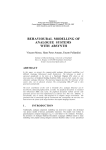
Figure 13: Synchronisation of two equivalent rotating masses
To estimate the shift times, the torque equilibrium for a synchronizer as in Figure 13 must be
solved.
TL +
dω
J red + TV + TR = 0
dt
Equation 4
When the master clutch is fully opened, the load moment TL is zero throughout the synchronizing
process. The torque losses TV are the result of bearing losses, oil churning losses, oil drag losses
and oil compression losses. These losses are specific in each individual transmission and should
be measured.
When shifting up, the gearwheel to be shifted is decelerated with the rotating masses reduced to
its axis Jred. Friction torque and torque losses act in the same direction. When shifting down, the
19
gearwheel to be shifted is accelerated with the rotating mass reduced to its axis. Friction torque
TL +
dω
J red + TV + TR = 0
dt
and torque losses act in opposite directions. With all this in mind
Equation 4 reduces to:
TR = −
dω
J red − TV
dt
For upshifts the term
Equation 5
dω
dt
becomes negative, and now it works in opposite direction of TV. With the
friction torque the friction work can be calculated using
2
W = − 12 ωt rTV − 12 J red ωmax
Equation 6.
2
W = − 12 ωt rTV − 12 J red ωmax
Equation 6
Dividing the friction work by the permissible slipping time results in the average friction power, as
in
P=
P=
W
tr
Equation 7.
W
tr
Equation 7
The permissible slipping time is defined as the time it takes to engage an idler gear. With the
friction torque and the dimensions of the synchromesh the force practiced on the synchromesh
sleeve can be obtained using the following equation:
F=
Tr 2 sin α
dμ
Using
TR = −
Equation 8
dω
J red − TV
dt
Equation 5 to
F=
Tr 2 sin α
dμ
Equation
8
several plots can be made with varying permissible slipping time. When the permissible slipping
time is known the corresponding values for Tr, W, P and F can be found. The maximum
permissible slipping time available for each gear change is stated in Table 3 and Table 4.
20
Figure 14: Upshift force
Figure 15: Critical down-shifts
21
7.3
Properties of the actuating system
Now we can calculate the maximum force the actuators can practice on the gear sleeves. The
maximum torque can be determined by
Mn =
P 60
= 0,252 Nm
n 2π
Mn =
P 60
= 0,252 Nm
n 2π
Equation 9.
Equation 9
With the maximum torque and the transmission ratio of the actuation system the maximum force
can be determined. The transmission ratio is 2500 rad/m, which is the total ratio including
everything from rotation of the electro motor till translation of the gear sleeve. The transmission
ratio is found in Appendix I..
F = M niactuation = 630 N
Equation 10
Now the maximum force the actuator can practice is known we can look at Figure 14 again, and
make the following table;
Gearshift
1 -> 2
2 -> 3
3 -> 4
4 -> 5
5 -> 6
Slip time [s]
0,65
0,22
0,09
0,045
0,04
Table 7: Upshift slip times
And for downshifts:
Gearshift
4 -> 1
6 -> 2
6 -> 3
6 -> 4
6 -> 5
Slip time [s]
4
0,95
0,22
0,1
0,07
Table 8: Slip time for downshifts
The required synchronization force is one component that determines the shift time. The other
component is the speed at which the actuation system can move from point A to point B, also
referred to as the free flight phase. When for example first gear is engaged and the system must
go to second gear, the gear sleeve must be moved twice the shift stroke. When a gear is
engaged the shift rod and gear sleeve stand completely still. So the electromotor should
accelerate then slow down, wait for synchronization (no full stop because of the shift elasticity),
move further as fast as possible and then make a stop after second gear is engaged. The
specifications of the electromotor are given in Appendix I. they determine the performance. One
parameter is not presented yet and that is the maximum angular velocity, being 5000 rev/min
which equals 524 rad/s.
The length of the shift stroke is 10 mm, from neutral position to when the gear is engaged, so
when another gear is engaged, the stroke must be covered twice, being 20 mm. With the given
22
specifications of the electromotor the resulting acceleration is plotted in Figure 16 and is
Mn = J
calculated with
Equation 11 .
dω
dt
Verdraaiing [rad]
40
30
20
10
0
0
0.01
0.02
0.03
0
0.01
0.02
0.03
0.04
0.05
0.06
0.07
0.04
0.05
0.06
0.07
600
Hoeksnelheid [rad/s]
500
400
300
200
100
0
Tijd [s]
Figure 16: Actuation speed
The displacement is calculated with the following function:
Mn = J
dω
dt
Equation 11
∂ω M n
rad
=
= 10080 2
∂t
s
J
Equation 12
ω = iactuation s
Equation 13
After t = 0,052 s the maximum velocity is reached.
23
Mn =
P 60
= 0,252 Nm
n 2π
7.4
Synchroniser performance limits
Equation
9
states it takes 25 radials to move from the engaged position to neutral. From Figure 16 can be
derived it would take 0,051 s to bridge this distance.
The time as stated above is the time required for a shift action, as in a shift from 1st to 2nd gear.
When shifting from 2nd to 3rd gear a selection movement must be made as well. However the
specifications of the selection motor are unknown. The reduction from rotation of the motor to
displacement of the selection rod is also unknown and the only information about the required
time can be derived from Figure 10. According to this figure it takes about 100 ms to complete
this action. From this figure it can also be concluded that before initiating the selection procedure
the shift-lever does not have to be in neutral. So it does not take an extra 100 ms when also a
selection action is required. For the length of the shift time, no concrete information can be
derived from the figure, because the circumstances are unknown.
In the preceding paragraphs the minimal shift time is calculated. However it is not sure the
synchromeshes can dissipate the heat that is generated at these shift speeds. If the synchronizer
has to process too much power, the tapers will become too hot, so the performance is determined
by the thermal stress. This causes the material properties to change which results in a lower
friction coefficient and thus a damaged synchronizer, which will not function properly any longer.
By calculating the specific frictional work, which is defined as the absolute work divided by the
various gross friction surface areas, the maximum permissible work can be defined.
WA =
W
Equation 14
AR
With the gross friction surface defined as:
d
AR = π N
2
(9,9 ⋅10 )
−3 2
⎛d ⎞
+⎜ N ⎟
⎝ 2 ⎠
2
Equation 15
With the data given in Appendix H., this results in an AR of 2,5E-3 m2. The synchronizer ring is
made of molybdenum. This material can deal with 0,53 J/mm2, resulting in a maximum
permissible work of 1325 W. Transient peak loads significantly higher than those given may be
tolerated. The peak value for specific frictional work WA in the synchronizer ring friction linings for
molybdenum is 1,5 J/mm2, allowing a work of 3750 W. Additional parameters are the permissible
friction speed, power and contact pressure. All these values are calculated in a Matlab script in
Appendix C..
Running this file leads to the following conclusion: the synchromeshes are too small to shift this
fast. In the worst case scenario the maximum transmitted power for an upshift is 2,03E5 where
the maximum power allowed is only 2,12 ⋅10
will be damaged.
Unity
|W|
|P|
|F|
−3
as in Table 9. In this situation the synchromeshes
Permitted value
1,34E3
2,12E3
1,52E4
Table 9: Values of check_ist.m
24
Figure 17: Left; upshift work, Right; downshift work
25
Figure 18: Left; upshift power, Right; downshift power
In Figure 17 and Figure 18 the values in the table are very obvious as well as the impact on the
permissible slipping time. At upshifts the only problem is the shift action from 1st to 2nd gear,
limiting the permissible slipping time to a minimum of0,4 seconds. When shifting down the
thermal performance of the synchronizer is a bigger limitation, especially when shifting from 4th to
1st gear.
26
8 Interpretation of the results
First we will compare the required shift times with the calculated shift times of the actuation
system. We can combine Table 3 with Table 7 and Table 4 with Table 8, however this is not a fair
comparison because Table 7 and Table 8 represent only the synchronization time. The time the
actuator needs to move from the engaged to the chosen idler gear must be added.
Gearshift
1 -> 2
2 -> 3
3 -> 4
4 -> 5
5 -> 6
Minimum achievable slip time [s]
0,701
0,371
0,141
0,196
0,091
Desired slip time [s]
0,44
0,93
0,2
0,2
0,2
Table 10: Comparison achievable and desired upshift times
Gearshift
4 -> 1
6 -> 2
6 -> 3
6 -> 4
6 -> 5
Minimum achievable slip time [s]
4,151
0,201
0,22
0,151
0,221
Desired slip time [s]
1,62
0,45
0,47
0,66
1,23
Table 11: Comparison achievable and desired downshift times
When changing to a higher gear there are not a lot of problems, only changing from first to
second gear takes too long. When shifting to a lower gear however a problem occurs when
shifting from fourth to first gear. This takes very long and this is due to the high inertia of the
gearbox, which is a result of the first gear ratio.
Now that the minima of the shift times in the worst-case scenario are calculated and the minimum
shift times looking at the thermal stress expressed by permissible work and power, these results
should be compared. The minimum slip time for the calculated gear changes were given in Table
7 and Table 8. The minimum shift times when looking at the thermal stresses are shown in Figure
18.
Gearshift
1 -> 2
2 -> 3
3 -> 4
4 -> 5
5 -> 6
Slip time [s]
0,39
0,11
0,03
Less then 0,03
Less then 0,03
Table 12: Minimum thermal slip times for upshifts
Gearshift
4 -> 1
6 -> 2
6 -> 3
6 -> 4
6 -> 5
Slip time [s]
4
0,5
0,05
Less then 0,03
Less then 0,03
Table 13: Minimum thermal slip times at downshifts
When looking at these tables we can conclude that the thermal restrictions are not exceeded yet.
When we take a look at the minimum thermal slip times for all gear changes and compare them
with the required specifications, the following remarks can be made.
27
A stronger electromotor can be used to increase performance since the synchronizers do not
carry their maximum load yet. However shifting from fourth to first gear can not be much faster
and a more powerful electromotor would cause damage to the friction material of the first gear.
The remaining gear changes meet their desired specifications. These calculations are done in
case of a worst case scenario, so when driving normal and shifting with a more likely engine
speed, like for example at maximum torque of the engine, the Easytronic system would be
applicable, with an exception for the fourth to first gear change at maximum engine speed.
28
9 Conclusions and recommendations
9.1
Conclusions
An electromechanical actuation system has some obvious advantages compared to a hydraulic
actuation system, especially in the field of cost and packaging. Its lower power density is its main
disadvantage, but we have seen from the calculations that it should perform quite well.
More over it is possible to increase performance, which is desired at upshifts. The increase in
performance can be obtained by fitting a more powerful electromotor. However thermal
restrictions have to be taken into account, since the performanceof the synchromeshes will be
met.
9.2
Recommendations
Some important parameters used in the calculations and which are stated in the specification
sheet in Appendix H. might differ from reality, and these parameters should be checked. Also the
parameters of the specific work, power and contact pressure are not from this transmission so
they could be wrong.
29
10 Bibliography
1. Antrieb und Getriebe – Aral
2. De complexe aandrijflijn – Kluwer technische boeken
3. Automatische Fahrzeuggetriebe – Springer-Verlag
4. Automotive Transmissions – Fundamentals, selection, design and application – G.
Lechner, H. Naunheimer, Springer
5. De elektronische versnellingsbak, Zelfstudieprogramma 221 – Constructie en werking
6. Technology survey on smartness added to automotive manual transmissions – J.D.W. de
Cock
7. Das tribologische Verhalten von Syncrhonisierungen unter Berücksichtigung
8. Beanspruchungskollektivs – Dipl. –Ing. Tobias Lösche 1997
9. Getriebe in Fahrzeugen 2001 – VDI-Berichte 1610
10. Patent number GB2316723
11. Patent number GB2313886
12. Patent number WO03087632
13. Patent number DE19725816
14. Patent number WO03087628
15. Patent number WO03081091
30
Appendix A.
Synchromesh dimensions
F
F
FN
α
FN
dc
d0
d
Figure 19: Schematic representation of a synchromesh
The symbols used in Figure 19 are:
d
d0
dC
F
FN
s
α
Effective diameter
Nominal diameter
Clutch diameter
Gear shift effort
Normal force
shift movement at the gearshift sleeve
Taper angle
31
The steps in the synchronization process
Figure 20: Syncrhonisation process
32
Appendix B.
Figure 21: Position 1
Figure 22: Position 2
33
Appendix C.
Synchromesh_sti.m
% Calculation of the shift force
clear all, close all, clc, format long
% Gearbox specific parameters
sti
rev_change_sti
% General and estimated
T_V = 2;
F_Hperm = 100;
t_Rperm = 0.25;
F_kies = 60;
parameters
% [Nm] Torque losses
% [N]
Permitted hand shift force
% [s]
Permitted slip time
% [N]
selection force (30-60)
% Slip time
t_begin = .02;
t_stap = .01;
t_eind = 1;
% Start time
% time step size
% End
% are the tapers self-locking?
if tan(alpha) >= mu
disp('No self-locking occurs')
else disp('Self-locking of the tapers')
end
% Calculating opening torque
%T_Z = F_a*d_C/2*((cos(beta/2)mu_D.*sin(beta/2))/(sin(beta/2)+mu_D*cos(beta/2)));
% T_Z = 1/2*F_a*d*acos(beta/2) vereenvoudiging, negeren van de frictie
coefficient mu_D
for u = 1:2 %u == 1 upshift, u == 2 downshift
% maximum difference in sliding velocity
v_max = omega_max(:,u)*d_N/2;
% also possible with omega
T_r = [];
W = [];
P = [];
Ps = [];
for t_r = t_begin:t_stap:t_eind
% Required friction torque
T_r_tmp = -J_red.*omega_max(:,u)/t_r-T_V;
T_r = [T_r,T_r_tmp];
% Friction work per shift action
W_tmp = -1/2.*omega_max(:,u)*t_r.*T_V1/2.*J_red.*omega_max(:,u).^2;
W = [W,W_tmp];
% Mean friction power
P_tmp = W_tmp/t_r;
P = [P,P_tmp];
% Power transmitted momentarily to the synchromesh
%Ps_tmp = T_r_tmp.*omega_max(:,u);
34
%Ps = [Ps,Ps_tmp];
end
% Results in the required axial force belonging to a certain slip
time
F = T_r*(2*sin(alpha))/(d*mu);
% Correct for the number of friction tapers
for l = 1:(length(ratios)-1)
F(l,:) = F(l,:)/j(l);
end
if u == 1
T_r_up = T_r; W_up = W; P_up = P; Ps_up = Ps; F_up = F;
end
if u == 2
T_r_down = T_r; W_down = W; P_down = P; Ps_down = Ps; F_down =
F;
end
clear F P W T_r Ps
end
Check_ist
% Plotten the results
t_r = t_begin:t_stap:t_eind;
% Time axis for plotting
figure
plot(F_up,t_r), title('Upshift')
xlabel('Gearshift effort at sleeve F [N]'), ylabel('Permissable slip
time t_r [s]')
axis([0 1500 0 0.7]), legend('1->2','2->3','3->4','4->5','5->6',1),
grid on
figure
subplot(122)
plot(W_down,t_r)
xlabel('Friction Work W [J]'), title('Downshifts')
axis([-5000 0 0 1]), legend('4->1','6->2','6->3','6->4','6->5',2), grid
on
subplot(121)
plot(W_up,t_r)
xlabel('Frictional Work W [J]'), ylabel('Permissable slip time t_r
[s]'), title('Upshifts'), axis([-1500 0 0 1])
legend('1->2','2->3','3->4','4->5','5->6',1), grid on
figure
subplot(121)
plot(abs(P_up)/1000,t_r)
xlabel('Power [kW]'), ylabel('Permissable slip time t_r [s]'),
title('Mean friction power at upshift')
axis([0 10 0 0.7]), legend('1->2','2->3','3->4','4->5','5->6',1), grid
on
subplot(122)
plot(abs(P_down)/1000,t_r)
xlabel('Power [kW]'), title('Mean friction power at downshift')
axis([0 10 0 1]), legend('4->1','6->2','6->3','6->4','6->5',2), grid on
35
figure
plot(F_down,t_r), title('Downshift')
xlabel('Gearshift effort at sleeve F [N]'), ylabel('Permissable slip
time t_r [s]')
axis([-3500 0 0 t_eind]), legend('4->1','6->2','6->3','6->4','6->5',2),
hold on, grid on
figure
plot(T_r_down,t_r), xlabel('Friction Torque T_r [Nm]'), axis('tight'),
hold on
plot(W_down,t_r)
xlabel('Frictional Work W [J]'), axis('tight')
% *(1) Das tribologische Verhalten von synchronisierungen unter
Berucksichtigung des Beanspruchungskollektivs KSN 97 LOE
% *(2) blz 246 Lechner & Naunheimer
36
Appendix D.
Sti.m
% Parameters voor versnellingsbak Volkswagen 02K DNZ in combinatie met
STI
scale = (65/23)*1e-3;
% [-]
schaal van de tekening
rho = 7800;
gebruikte tandwielen
% [kg/m^3]
dichtheid materiaal
% Versnellingsbak specifieke parameters
mu = .1;
% [-]
gemiddelde
wrijvingswaarde in het konusvlak *(1)
alpha = 11.42*pi/180;
% [rad]
halve kegelhoek van de
synchronisers
beta = 115*pi/180;
% [rad]
kegel hoek / opening
angle van de tanden op de synchronisers
d = 54e-3;
% [m]
effectieve diameter
(halverwege wrijvingsopp synchro)
d_C = 70e-3;
% [m]
clutch diameter (v.d.
synchromesh waar de dogs zitten)
d_N = 55e-3;
% [m]
nominal diameter
% voor definities van bovenstaande drie zie *(1) blz 234
i_actuation = 2500;
% [rad/m]
Total gear ratio of the
actuation part
h = 65e-3;
% [m]
hartafstand tussen
prise en pignont as
omega = [650 650 650 650 565 332]; % [rad/s] toerental waarbij
geschakeld wordt (worst-case maxvermogen@ 6200 rpm, maxkoppel@ 3200
rpm)
s = 10e-3;
% [m]
Weg die de gearshift
sleeve aflegt 10-13 [mm]
j = [1,1,1,1,1,1];
% [-]
Allemaal enkele
wrijvingsvlakken volgens Christian
z = [11,38,18,35,28,36,32,31,41,33,55,31]; %
3e versnelling wordt
6e, tandwielen omdraaien nog niet gedaan
ratios = [z(2)/z(1) z(4)/z(3) z(6)/z(5) z(8)/z(7) z(10)/z(9)
z(12)/z(11)];
%
Wordt gevraagd door synchromesh.m
i_diff = 68/18;
% [-]
overbrenging
differentieel
% Gemeten waarden uit tekening
% Traagheid ingaande as
L_as = [29,4,8,1,11,10,9]*scale;
% van rechts naar links op de
tekening plus synchromeshes
D_as = [7,9,9,14,28,9,28]*scale;
% idem ook inclusief de
synchromeshes
D_as_i = 4*scale;
% inwendige diameter, uitsparing
voor pen van de koppelingsbediening
J_IS = (sum((D_as.^4).*L_as)-D_as_i^4*sum(L_as))*(pi/32*rho);
%Traagheid Koppeling
D_clutch = [0.03 0.14 210e-3];
% gedeeltelijk uit easydata
D_clutch_i = [0.02 0.03 0.14];
% uit easydata
d_clutch = [0.04 0.011 0.0007];
% ook uit easydata
37
J_C = (sum((D_clutch.^4).*d_clutch)sum((D_clutch_i.^4).*d_clutch))*(pi/32*rho);
% Traagheid J1
d1 = [6,3]*scale;
D1 = [12,9]*scale;
J(1) = sum((D1.^4).*d1);
% Traagheid J2
d2 = [5,1]*scale;
D2 = [38,30]*scale;
J(2) = sum((D2.^4).*d2);
% Traagheid J3
d3 = [5]*scale;
D3 = [12]*scale;
J(3) = sum((D3.^4).*d3);
% Traagheid J4
d4 = [5]*scale;
D4 = [34]*scale;
J(4) = sum((D4.^4).*d4);
% Traagheid J5
d5 = [5]*scale;
D5 = [21]*scale;
J(5) = sum((D5.^4).*d5);
% Traagheid J6
d6 = [5]*scale;
D6 = [29]*scale;
J(6) = sum((D6.^4).*d6);
% Traagheid J7
d7 = [5]*scale;
D7 = [28]*scale;
J(7) = sum((D7.^4).*d7);
% Traagheid J8
d8 = [5]*scale;
D8 = [22]*scale;
J(8) = sum((D8.^4).*d8);
% Traagheid J9
d9 = [5]*scale;
D9 = [27]*scale;
J(9) = sum((D9.^4).*d9);
% Traagheid J10
d10 = [5]*scale;
D10 = [23]*scale;
J(10) = sum((D10.^4).*d10);
% Traagheid van J1 t/m J6 reduceren, omdat ze hol zijn
d_i =
[sum(d1),sum(d2),sum(d3),sum(d4),sum(d5),sum(d6),sum(d7),sum(d8),sum(d9
),sum(d10)];
D_i = [4,5,4,5,4,5,4,5,4,5]*scale;
%
binnendiameters J1,J2..,J10
J_i = (D_i.^4).*d_i;
J = (J-J_i)*(pi/32*rho);
%
corrigeren van traagheden en opslaan in een rij
%Berekende waarden van de diameters en hierbij behorende traagheden ter
controle
for k = 1:2:10
Db(k) = 2*(z(k)/z(k+1)*h)/(z(k)/z(k+1)+1);
Db(k+1) = 2*h/(z(k)/z(k+1)+1);
38
end
Jb = ((Db.^4).*5)*(pi/32*rho);
% Gereduceerde traagheden bepalen zodat er met 1 hoeksnelheid gerekend
kan worden
J_red(1,1) =
J(2)+(J_IS+J_C+J(1)+J(3)+J(4)*(z(3)/z(4))^2)*(z(2)/z(1))^2;
J_red(2,1) =
J(4)+(J_IS+J_C+J(1)+J(3)+J(2)*(z(1)/z(2))^2)*(z(4)/z(3))^2;
J_red(3,1) =
(J_IS+J_C+J(1)+J(3)+(J(4)*(z(3)/z(4))^2+J(2)*(z(1)/z(2))^2))*(z(6)/z(5)
)^2;
J_red(4,1) =
(J_IS+J_C+J(1)+J(3)+(J(4)*(z(3)/z(4))^2+J(2)*(z(1)/z(2))^2))*(z(8)/z(7)
)^2;
J_red(5,1) =
(J_IS+J_C+J(1)+J(3)+(J(4)*(z(3)/z(4))^2+J(2)*(z(1)/z(2))^2))*(z(10)/z(9
))^2;
J_red(6,1) =
(J_IS+J_C+J(1)+J(3)+(J(4)*(z(3)/z(4))^2+J(2)*(z(1)/z(2))^2))*(z(12)/z(1
1))^2;
39
Appendix E.
Actuatie.m
% Actuatie berekeningen
% Gegevens van de actuator
n = 5000;
m = .813;
V = 162;
omega_max = n*2*pi/60;
J_schalt = 25e-6;
P = 163*m;
tau = 7.46e-3;
phi = s*i_actuatie_totaal;
%[omw/min]
%[kg]
%[W/kg] Vermogensdichtheid
%[rad/s]
%[kgm^2]
%[W]
%[s]
%[rad] hoekverdraaing motor
M = P/omega_max;
max_accel = M/J_schalt;
t_v_max = omega_max/max_accel;
F_shift = M*i_actuation;
%[Nm]
%[rad/s^2]
%[s]
%[N]
t_tmp=0;
t = [];
omega = [];
omega_tmp = 0;
k = [];
k_tmp = 0;
while k_tmp < phi
if omega_tmp < omega_max
omega_tmp = max_accel*t_tmp;
k_tmp = omega_tmp*t_tmp;
else
k_tmp = omega_max*t_tmp;
end
omega = [omega,omega_tmp];
k = [k,k_tmp];
t_tmp=t_tmp+.001;
t = [t,t_tmp];
end
subplot(211)
plot(t,k)
ylabel('Angle [rad]')
subplot(212)
plot(t,omega)
ylabel('Angular velocity [rad/s]'),xlabel('Time [s]')
axis('tight')
40
Appendix A.
Rev_change_sti.m
% Opschakel acties, 1->2,2->3,3->4,4->5,5->6, sequentieel
%Opschakelen
for k = 1:(length(ratios)-1);
omega_up(k,1) = omega(k)*(ratios(k+1)/ratios(k))-omega(k);
end
omega_up = [0;omega_up]; % toevoegen van een nul om dat 0->1 met de
koppeling gebeurt
% Te bepalen terugschakel acties
% 2->1 3->1 4->1
% 3->2 4->2 5->2 6->2
% 4->3 5->3 6->3
% 5->4 6->4
% 6->5
v_car = [30,25,40,50,50,60,60,80,80,60,100,80,140]/3.6;
g = [2,3,4,3,4,5,6,4,5,6,5,6,6];
r_tire = .316;
%Terugschakelen
omega1 = [];
for k = 1:3;
omega_engine = v_car(k)/r_tire*(ratios(g(k))*i_diff);
omega1_tmp = omega_engine*ratios(1)/ratios(g(k))-omega_engine;
omega1 = [omega1;omega1_tmp];
end
t1 = [0.73; 0.92; 1.62];
dwdt1 = omega1./t1;
omega2 = [];
for k = 4:7;
omega_engine = v_car(k)/r_tire*(ratios(g(k))*i_diff);
omega2_tmp = omega_engine*ratios(2)/ratios(g(k))-omega_engine;
omega2 = [omega2;omega2_tmp];
end
t2 = [0.46; 0.72; 0.98; 1];
dwdt2 = omega2./t2;
omega3 = [];
for k = 8:10;
omega_engine = v_car(k)/r_tire*(ratios(g(k))*i_diff);
omega3_tmp = omega_engine*ratios(3)/ratios(g(k))-omega_engine;
omega3 = [omega3;omega3_tmp];
end
t3 = [0.35; 0.55; 0.65];
dwdt3 = omega3./t3;
omega4 = [];
for k = 11:12;
omega_engine = v_car(k)/r_tire*(ratios(g(k))*i_diff);
omega4_tmp = omega_engine*ratios(4)/ratios(g(k))-omega_engine;
omega4 = [omega4;omega4_tmp];
end
t4 = [0.25; 0.47];
dwdt4 = omega4./t4;
omega5 = [];
for k = 13;
41
omega_engine = v_car(k)/r_tire*(ratios(g(k))*i_diff);
omega5_tmp = omega_engine*ratios(5)/ratios(g(k))-omega_engine;
omega5 = [omega5;omega5_tmp];
end
t5 = 0.45;
dwdt5 = omega5/t5;
% Determining the most critical shift actions
[y,n] = max(dwdt1);
[y.n] = max(dwdt2);
[y.n] = max(dwdt3);
[y.n] = max(dwdt4);
[y.n] = max(dwdt5);
omega_down =
[max(omega1);max(omega2);max(omega3);max(omega4);max(omega5);0];
omega_max = [omega_up, omega_down]; % adapting for synchromesh_sti.m
42
Appendix F.
Check_ist.m
% Checking the results of synchromesh_sti.n
% Parameters - molybdenum
W_A = 0.53;
% [J/mm^2]
W_A_peak = 1.5; % [J/mm^2]
P_A = 0.84;
% [W/mm^2]
p_R = 6;
% [N/mm^2]
v_perm = 7;
% [m/s]
Specific frictional work
Specific frictional work at peak load
Specific frictional power
Contact pressure
Permissible friction speed
% Calculations
A_R = 1e6*(pi*d_N/2*sqrt((9.9e-3)^2+(d_N/2)^2));
W_perm = W_A*A_R;
W_perm_peak = W_A_peak*A_R;
P_perm = P_A*A_R;
F_perm = p_R*A_R;
% Comparison - results
if W_perm > max(max(abs(W_up)))
disp('Upshift frictional work is within limits')
else
disp('Upshift frictional work is too large')
end
if W_perm > max(max(abs(W_down)))
disp('Downshift frictional work is within limits')
else
disp('Downshift frictional work is too large')
end
if P_perm > max(max(abs(P_up))) % Momentarily transmitted power
disp('Upshift specific friciton power is ok')
else
disp('Upshift specific friction power is too large')
end
if P_perm > max(max(abs(P_down)))
disp('Downshift specific friciton power is ok')
else
disp('Downshift specific friction power is too large')
end
if F_perm > max(max(abs(F_up)))
disp('Upshift contact pressure is ok')
else
disp('Upshift contact pressure is too large')
end
if F_perm > max(max(abs(F_down)))
disp('Downshift contact pressure is ok')
else
disp('Downshift contact pressure is too large')
end
43
Appendix G.
44
45
46
Appendix H.
Parameter
Geschatte Waarde
Gemeten Waarde
Eenheid
Symbool
Hoe te verkrijgen
7
10
mm
s
Meten
Synchromesh
afstand die schakelmof aflegt (van neutral tot synchro ring)
aantal wrijvingsvlakken in synchromesh
j
kijken
naar 1 of 2
1
1
j1
kijken
naar 4 of 6
1
1
j2
kijken
naar 5
1
1
j3
kijken
6,5
11,42
graden
alpha
meten
halve kegelhoek synchroniser
115
opening angle tanden van de dogs
graden
beta
meten
0,054
m
d
meten
6.90E-02
0,07
m
d_C
Meten
6.00E-02
0,055
m
d_N
Meten
mu
afschatten
d
meten
effectieve diameter
5.70E-02
clutch diameter
nominale diameter
0.1
wrijvingscoefficienten
7800
dichtheid
6250
Versnellingsbak
dikte tandwielen
tandwiel 1 (zie schematische tekening)
0.0170
0.0085
tandwiel 2
0.0141
0.0028
17,3E-3 23,8E-3
m
d1
1,4E-2
m
d2
tandwiel 3
0.0141
1,53E-2
m
d3
tandwiel 4
0.0141
1,48E-2
m
d4
tandwiel 5
0.0141
1,46E-2
m
d5
tandwiel 6
0.0141
1,55E-2
m
d6
tandwiel 7
0.0141
1,48E-2
m
d7
tandwiel 8
0.0141
1,52E-2
m
d8
tandwiel 9
0.0141
1,54E-2
m
d9
tandwiel 10
0.0141
1,41E-2
m
d10
Lengte van prise as
L_IS
Lengte van pignont as
L_OS
meten
0.0017
J_IS
afschatten en uitrekenen
J_red
afschatten en uitrekenen
naar 1
0.0743
J_red1
naar 2
0.0235
J_red2
naar 3
0.0103
J_red3
naar 4
0.0058
J_red4
naar 5
0.004
J_red5
naar 6
0.002
traagheid ingaande as
Gereduceerde traagheden
J_red6
N
Stijfheid veren op de schakelas
Overbrengingsverhoudingen (automotive notatie)
3,45 1,94 1,29 0,97 0,8
Hartafstand prise as en pignont as
65
Toerental waarbij geschakeld wordt
meten
ok
k
meten
ratios
bekend
mm
h
bekend
rad/s
omega
van Christian
in 1
650
rad/s
omega1
in 2
650
rad/s
omega2
in 3
650
rad/s
omega3
in 4
650
rad/s
omega4
in 5
565
rad/s
omega5
in 6
332
rad/s
omega6
Koppel verliezen in de versnellingsbak
2
Nm
T_V
geschat lechner
Kieskracht
60
N
F_kies
geschat lechner
maximale omwentelingssnelheid schakelactuator
5000
omw/min
n
LuK kap 13 .pdf
massa schakelactuator
0.813
kg
m
LuK kap 13 .pdf
traagheid schakel motor
2.50E-05
kg*m^2
J_schalt
LuK kap 13 .pdf
LuK kap 13 .pdf
Actuatie gedeelte
maximale vermogen
132.5
W
P
nominaal koppel
0.2531
Nm
M
berekend
2500
rad/m
i_actuatie_totaal
patent schakelelasticiteit.pdf
totale overbrenging schakelactie
Table 14: Dimension and parameter survey
47
Appendix I.
48