1
Solar Powered Cycling Computer
Item #: 500-111
www.vetta-china.com
CONTENTS
Warnings & Cautions....................................... 3
Introduction...................................................... 3
Functions & Features.......................................4
Illustrations.......................................................5
LCD Display..................................................... 6
Button Functions.............................................. 7
Battery Introduction..........................................8
Installation........................................................9
Mounting Bracket.......................................... 9
Wired Speed Sensor & Magnet....................11
Head Unit.........................................................13
Installation Tests..............................................14
Setup & Programming.....................................15
1
Functions.........................................................26
Other Features................................................31
All Clear Total Reset........................................33
Trouble Shooting.............................................34
Warranty Policy...............................................36
2
WARNINGS & CAUTIONS
It is recommended that the product is to be installed
by a qualified bicycle retailer. Failure to read the
instructions and / or improper installation of the device
may void the warranty. If you have any doubts about
the installation or the operations, contact your local
bicycle retailer for clarification.
down on the upper portion of the display to activate
the rear mounted button and cycle through the array
of functions featured on the Solar Flare.
FUNCTIONS & FEATURES
Features & Functions
Heavy-Duty Wired Speed
Service Timer
Speed Comparator
Speed (Current / AVG / MAX)
Ride Time
Cumulative Odometer
Trip Distance
EZ Tire Setup
12/24 Hour Clock
INTRODUCTION
The Solar Flare utilizes solar cells to power the
computer in order to minimize impact on our
environment. In addition to being greener than
conventional cycling computers, the Solar Flare is
also more convenient because it allows users to stop
worrying about battery life.
Buttons have been eliminated from the face of the
Solar Flare. Instead, users simply press the face
3
4
Solar Flare
¥
¥
¥
¥
¥
¥
¥
¥
¥
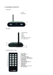
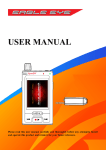
ILLUSTRATIONS
LCD Display
Head Unit
7
6
Press the face down
3
1
4
5
1
2
8
9
10
2
11
1. Button 1
2. Button 2
Note: When the computer is mounted on the bike,
simply press the face down on the upper portion
of the display to activate Button 2 .
5
1. Upper Display (Speed)
2. Lower Display (Time / Clock)
3. Speed Comparator
4. Speed / Distance Units
5. Service Timer
6. Speed Icon
6
7. Setup Mode Icon
8. Max./ AVG Icon
9. Odometer / Distance Icon
10. RT / PM Icon
11. Time Icon
Button 2 when the lowest screen is in the DST Mode:
Reset ride data to zero.
2 All Clear Total Reset
Button 1 & :
BUTTON FUNCTIONS
In Set Up Mode
Button 1 : Switch between settings and scroll through
values(0~9).
Button 2 : Select or set a value and advance to the
next digit or Mode.
BATTERY INTRODUCTION
Sunlight
In Operation Mode
Solar Panels
Press momentarily
Button 1 : Cycle through top screen.
Button 2 : Press Upper portion of screen to cycle
through lower screen views.
Solar Panels
Sunlight
Press & hold for 2 seconds
Button 1 when the lowest screen is in the CLK Mode:
NOM Setup.
7
Solar Flare utilizes solar
power and a CR2032,
3.6 Volt Rechargeable
Lithium Ion battery.
When sunlight shines
onto the solar panels
(on both upper and
lower portions of the
computer), it charges
the battery and provides
power to the computer.
Note:
The battery is factory installed and has a shelf life of
8
2 months without exposure to sunlight.
The CR2032 rechargeable lithium Ion battery will
provide power to the computer when sunlight is not
available (during storage or evening).
Rubber Pad
INSTALLATION
Screw Strap
Mounting Bracket
Mounting Bracket to be mounted on the handle bar
Install Screw Strap & Rubber Pad to the Mounting
Bracket
Install the Mounting Bracket
Rubber Pad
Screw Strap
On the Stem
On the Handle Bar
Attach Mounting Bracket to the handlebar on the
“Sensor side” or on the stem as shown in the
pictures above.
Mounting Bracket to be mounted on the stem
9
10
Adjust its position so it can be read while riding and
then tighten the Screw Strap.
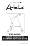
Wired Speed Sensor & Magnet
Bladed Spoke
Magnet
Zip-Tie
Spoke
Wired Speed
Sensor
Fork Leg
Magnet
Sweep Path
Bladed
Spoke Magnet
Spacer
Spoke
Bladed
Spoke Magnet
Spacer Tip
1. Attach the wired speed sensor with the zip-ties
supplied.
2. Tighten the bladed spoke magnet to the bicycle.
3. Adjust the sensor & magnet spacing with the spacer.
4. Remove the spacer after tightening the zip-ties
down to hold the sensor in its final position.
Note: Mount the sensor as high up on the fork leg as
possible.
Important: Use the tape provided in the package
rather than the Zip-Ties to hold wires to the frame,
fork, and bars or stem to avoid damaging or cutting
the wires accidentally. Make sure excess wire is
taped down or wrapped around brake cable housing
to secure it.
Alignment
Mark
Note: Be sure to leave enough slack in the wire to
accommodate the movement of the fork.
Bladed
Spoke Magnet
Wired Speed
Sensor
11
12
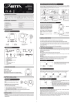
INSTALLATION TESTS
Head Unit
Slide the Head Unit into the Mounting
Bracket as shown until it clicks into
position.
Detaching the Head Unit
Slide out the Head Unit by pressing the
Locking Tab simultaneously
To test the Speed Sensor installation
Pick up the front of the bicycle and spin the front
wheel. The LCD should display a speed reading
within 2-3 seconds.
If there is no speed reading, check the alignment and
spacing between the magnet and sensor. Make sure
that the Head Unit is completely locked into position.
If the problem has not been fixed, go to
http://www.vetta.com/support/support.asp or talk to
an authorized Vetta Retailer for additional support.
Once the sensor is aligned, tighten the magnet
locking screw and bike mount strap.
Press
Locking Tab
13
14
The computer will automatically exit the Setup Mode
after complete all the basic settings.
SETUP & PROGRAMMING
In Setup:
Button 1 is used to switch between settings and to
scroll through values(0~9).
Button is
used to select or set a value and to
2
advance to the next digit or mode.
SETUP: 12/24 CLOCK
1
Initial Setup
Press either button to exit Shelf Mode and enter the
Initial Setup when first use this cycling computer.
Note: In Shelf Mode, there is nothing shown in the
1
Press Button to
toggle between flashing 12 and 24
hour formats.
2
Press Button to
select your desired format (without
PM icon implies AM in 12 hour format) and advance
to Time setting.
LCD screen.
NOM Setup
To enter the NOM Setup Mode, press & hold Button
1 when the lowest screen is in the CLK Mode.
15
16
SETUP: SPEED/ DISTANCE UNIT
SETUP: TIME
1
1
2
Press Button 1 to advance hour
1
1
Press Button to
toggle between flashing M/hr
and KM/hr.
2 to select and advance the next
Press Button Setup Mode.
digits to correct hour (press & hold
button for fast advance).
Press Button 2 to select and
Note: If the ride data is NOT cleared before entering
the Setup Mode, they will be automatically
converted to values based upon the new Speed
/ Distance Unit.
advance to minute setting.
Press Button 1 to advance minute
digits to correct minute.
Press Button 2 to select and
advance to the next Setup Mode.
17
18
The default settings “0000” means the Service Timer
is turned off.
SETUP: SERVICE TIMER
2
1
2
Choose the Service Timer Unit
Press Button 1 to scroll and select (hour),
(day)
or
(distance) as the Service Timer Unit.
Press Button 2 to confirm the selection of Serveice
Timer Unit.
1
2
1
2
When the desired Service Timer unit has been chosen
1
2
1
Press Button 1 to scroll the flashing digit to the
desired number.
2
Service Timer could be programmed with a selected
number of ride time (hours or days) or distance as the
interval for servicing the bicycle or any component on
it, such as a front or rear shock.
19
2
Press Button to
select this number and advance
to next digit. Repeat this procedure until all digits are
set.
2
Press Button to
advance to the next Setup Mode.
(Maximum settings: hour / day / distance =1999/199/9999)
20
Important: In the Initial Setup, the elapsed time / distance
for Service Timer does not exist.
Reset Service Timer to Zero
OR
2
OR
2
SETUP: WHEEL / TIRE SIZE
2
2
1
2
2
2
2
1
When the Ride Time (the elapsed time for Service
Timer) begins to flash
1 to reset to zero;
Press Button OR
2
Press Button to
reserve the digits, and advance
to the next Setup Mode.
21
Press Button 1 to toggle between flashing CIRC
(Circumference) and TIRE (Tire Type).
Press Button 2 to confirm selection and continue
the settings.
22
If you choose CIRC (Circumference) (See Table
of Tire Size Vs Circ)
Press Button 1 to adjust the falshing digit to the
desired number.
Press Button 2 to select this number and advance
to next digit.
Repeat this procedure until all four digits are set.
If you choose TIRE (Tire Size)
1 to scroll through the falshing 700c,
Press Button 650c,27in,26in,24in,22in,20in,16in or 12in and select
the wheel size.
2
Press Button to
select and advance to next setting
to complete the Tire Size.
2
1 to scroll and press Button Again, press Button to finalize the Tire Size and advance to the next
Setup Mode.
23
TIRE SIZE
700c x 38mm
700c x 35mm
700c x 32mm
700c x 32mm
700c x 28mm
700c x 25mm
700c x 23mm
700c x 20mm
700c Tubular
650c x 23mm
650c x 20mm
27” x 1.25”
27” x 1.125”
26” x 2.3”
24
CIRC
2180
2168
2155
2145
2136
2124
2105
2074
2130
1990
1945
2161
2155
2135
TIRE SIZE
26” x 2.25”
26” x 2.1”
26” x 2.0”
26” x 1.9/1.95”
26” x 1.75”
26” x 1.5”
26” x 1.25”
26” x 1.0”
24” x 1.9/1.95”
20” x 1.25”
16” x 2.0”
16” x 1.95”
16” x 1.5”
CIRC
2115
2095
2180
2055
2035
1985
1953
1913
1916
1618
1253
1257
1206
SETUP: ODOMETER
1
FUNCTIONS
1 to change the Upper Screen Modes.
Press Button 2
2
Press Button to
change the Lower Screen Modes.
To enter the NOM Setup Mode, press & hold Button
1 for 2 seconds when the lowest screen is in the CLK
2
Press Button 1 to scroll the
flashing digit to the desired
number.
Press Button 2 to select this
number and advance to next
digit. Repeat this procedure until
all five digits are selected
2 to advance to
Press Button next Setup Mode. (Maximum
setting: 99999).
Mode.
To reset all ride data to zero, press & hold Button 2
for 2 seconds when the lowest screen is in the DST
Mode.
25
26
Note: When the Ride Time exceeds 99 hours and 59
minutes, the computer will stop recording new data,
and the lower screen displays “HALT”.
SPD
Speed is shown at all times on
the upper display. It is accurate
to 0.1 M/hr or KM/hr and the
maximum reading is 139.9 M/hr
or 199.9 KM/hr.
DST
RT
DST displays trip distance of current ride to a
maximum of 999.9 miles or kilometers. It is accurate
to 0.1 Mile or KM.
RT displays actual, cumulative ride time to 100 hours.
[If the time is less than 9:59:59 hours, the display
format will be h:mm:ss, eg.0:09:59 means 9 minutes
and 59 seconds. If the time is longer than 10 hours,
the format will be hh:mm without seconds, eg 11:28
means 11 hours and 28 minutes ]
27
Note: When the Trip Distance exceeds 999.9 KM or
Miles, the computer will stop recording new data, and
the lower screen displays “HALT”.
28
AVG SPD
Maximum Speed is accurate to 0.1 M/hr or KM/hr.
Note: When the Ride Time exceeds 99 hours and 59
minutes, or the Trip Distance exceeds 999.9 miles
[kilometers], the computer will stop recording new
data, and the lower screen displays “HALT”.
ODO
Average Speed is accurate to 0.1 M/hr or KM/hr.
Note: When the Ride Time exceeds 99 hours and 59
minutes, or the Trip Distance exceeds 999.9 miles
[kilometers], the computer will stop recording new
data, and the lower screen displays “HALT”.
MAX SPD
The odometer displays distance to 99999 Miles or
Kilometers. It is accurate to 1.0 Mile or KM.
29
30
CLK
Computer enters Sleep Mode after 5 minutes without
input from any button or wheel, and displays the clock
only.
Computer exits Sleep Mode and returns to the screen
last displayed when any button is pressed or the
wheel turns.
Time [Clock] is displayed in user-selected 12 or 24
hour formats.
SERVICE TIMER (
)
OTHER FEATURES
SLEEP MODE
Blinking “ ” alerts riders when the Service Time is
reached.
31
32
63(('&203$5$725Ÿź
TROUBLE SHOOTING
Current speed-reading is erratic or does not appear.
&KHFNWKHDOLJQPHQWRIWKHEODGHGVSRNHPDJQHWDQG
VHQVRUDQGWKHGLVWDQFHEHWZHHQWKHWZRFRPSRQHQWV
OR,QVSHFWWKHZLULQJIRUDQ\EUHDNVRUNLQNV5HSODFH
0RXQWLQJ%UDFNHWDQGVHQVRUDVQHHGHG
Speed Comparator: Arrow symbols indicate if current
VSHHG LV VORZHU ź RU IDVWHU Ÿ WKDQ FXUUHQW DYHUDJH
speed.
Incorrect data appears on screen during operation.
$FFXUDF\RIWKH6HWXSGDWDPD\EHDSUREOHPZKHHO
VL]HVHWWLQJHWF
ALL CLEAR TOTAL RESET
$OOGDWDHQWHUHGLQWKH6HWXS0RGHVDVZHOODVULGHGDWD
FDQEHFOHDUHGE\SHUIRUPLQJDQ$OO&OHDU7RWDO5HVHW
2
1
7RFOHDUWKHFRPSXWHUSUHVVKROG%XWWRQ
VLPXOWDQHRXVO\IRUVHFRQGVLQDQ\0RGH7KHPDVWHU
VFUHHQ ZLOO DSSHDU DQG VKRZ DOO VHJPHQWV WKHQ
DXWRPDWLFDOO\HQWHUWKH6HWXS0RGH
33
Data display is extremely slow.
&RPSXWHU/&'VFUHHQRSHUDWHVWKHEHVWXQGHUWKH
IROORZLQJWHPSHUDWXUHUDQJH2SHUDWLQJUDQJHLV&
WR&RU)WR)
34
Screen is dark and display erratic characters.
Do not leave the computer in direct sunlight for extended
periods of time. Move the computer into the shade
until the screen recovers.
Noted: Data will not be affected.
Screen reading is weak or fading.
Symptom of a weak battery. Replace the battery.
Screen readings are erratic and read too high or
too low.
Symptom of a weak battery. Replace the battery.
Screen “frozen”, no response to buttons.
Symptom of a weak battery. Replace the battery.
No display whatsoever.
Battery is completely dead, or not installed. Replace
or install the battery.
35
WARRANTY POLICY
ACUMEN INC. WARRANTS ALL VETTA (The
Company) PRODUCTS AGAINST MANUFACTURER
DEFECTS FOR A PERIOD OF 3 YEARS. Subject to
the following limitations, terms and conditions,
components will be free of manufacturing defects in
materials and workmanship. The 3 year limited
warranty is conditioned upon the components being
used and operated in normal riding conditions. This
warranty does not cover normal wear and tear (i.e.
battery replacement, broken wire), rider abuse, acts
of God, improper installation or product alteration.
This warranty is void if the components were not
purchased (new) from or through an authorized
VETTA retailer or dealer. Examples of
unauthorized dealers are online auction sites or
online retailers.
36
ACUMEN INC. at its sole discretion will repair or
replace items at its own cost. Users are responsible
for all freight and shipping charges, when returning
items for warranty service.
ACUMEN INC. will pay the freight when returning
serviced items, via USPS or UPS to consumers or
dealers, once the item(s) has been repaired or
replaced.
In USA, securely pack and return the product prepaid
to:
Acumen Inc.,
101A Executive Drive Suite 100, Sterling, VA 20166 USA
REQUIREMENTS FOR WARRANTY SERVICING
1. Prior to shipping an item back, you must first obtain
a Return Authorization Number (s) (RA#). Each item
item being returned must have an individual RA#.
37
2. To obtain an RA #, you must either contact the retailer
where the product was originally purchased from, or
contact VETTA directly at customer service @
vetta.com.
3. We request that the complete unit with packaging be
returned to ACUMEN INC. unless otherwise stated by
VETTA representative.
ITEMS TO BE INCLUDED IN RETURNS
1. The defective product(s)
2. A letter clearly stating the problem(s) with the returned
item(s).
3. Copy of the original sales receipt showing proof of
purchase date.
4. The Company is not responsible for loss or additional
damages while in transit to ACUMEN INC.
5. Clearly mark the RA# on the outside of the return
packaging. All items without an RA # will be refused
and returned to the return address on the package.
38
The Company shall not be held responsible for
replacing items with new items for greater than the
amount of the original item purchase price. This
limited warranty does provide the original owner with
certain legal rights and recourse. The original owner
may possess other rights or recourse, depending on
the state or country. Please check the web to help
answer any question and service manual.
Outside USA, you should contact the local dealer or
Vetta distributor in your country for customer service.
Email: [email protected]
Website: www.vetta.com
39
40
Acumen Inc.
101A Executive Dr.,Suite 100, Sterling, VA 20166, USA
Email: [email protected]
Website: www.vetta.com