1
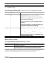
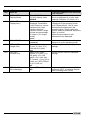
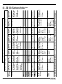
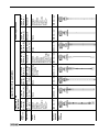
Function (Fct.)
1.3.0 CUR. OUTP. I
Input Range
1.3.1
FUNCTION.I.1
Select Off, Level,
Distance, Volume,
Interface Level*, Layer*,
Interface Distance*,
Interface Volume* or
Ullage Volume.
Level
1.3.2
RANGE.I 1
1.3.3
SCAL.I.1 MIN
(Scale I1 Minimum)
1.3.4
SCAL.I.1 MAX
(Scale I1 Maximum)
Select 4-20 mA, 4-20 mA
with a 3.7 mA failsafe
output or 4-20mA with a
22mA failsafe output.
4-20 mA, E=22mA
Enter value with regards
to measure method
selected in Fct.1.3.1 and
the units set in Fct. 1.2.5.
As per order or 0.0
Enter value as in 1.3.3
Description
This configures the current output.
These functions are independent
from what is displayed.
Assigns a measurement parameter to
analogue output number 1.
* These parameters are not displayed
in this sub-menu unless the
instrument is configured for interface
measurement.
Calibrate the gauge using Function
1.7.2 Strapping Table before selecting
“Volume” here.
Sets the analogue output range.
Settings with fail-safes will send an
error message if an error occurs i.e.
the level is lost.
Assigns a length or volume value to 4
mA.
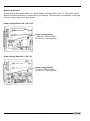
Refer to section 3.4.3, Example
Procedure 4.
Assigns a length or volume value to
20 mA.
Refer to section 3.4.3, Example
Tank height or probe
length as given in order Procedure 4.
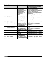
1.3.5 FUNCTION.I.2*
Select as in 1.3.1
Same as Fct. 1.3.1, except this is for
the second current output, if ordered.
Level
1.3.6 RANGE.I 2*
Select as in 1.3.2
Same as Fct. 1.3.2, except this is for
the second current output, if ordered.
4-20 mA
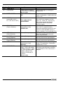
1.3.7 SCAL.I.2 MIN*
Enter value as in 1.3.3
Same as Fct. 1.3.3, except this is for
the second current output, if ordered.
As per order or 0.0
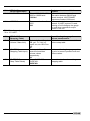
1.3.8 SCAL.I.2 MAX*
Enter value as in 1.3.4
As per order or Tank Height Same
As order or Tank Height as Fct. 1.3.4, except this is for the
second current output, if ordered.
*Displayed when interface measurement is selected in the factory menu
Handbook BM 100 A
35