1
0) rrloNeerl"
ORDER NO.
ARP-489-O
STEREODOUBLECASSETTETAPEDECK
AS FOLLOWS:
MODEL CT.OssWCOMESIN THREE VERSIONSDISTINGUISHED
o
o
o
o
Remarks
Voltage
Type
KU
A C 1 2 O Vo n l y
U . S . A .m o d e l
HEM
AC22OV. 24OV (switchable)
E u r o p e a nc o n t i n e n t m o d e l
HB
AC22OV. 240V (switchable)
United Kingdom model
to the KU, HEMand HB types.
Thisservicemanualis applicable
As to the HEM and HB typespleasereferto pages68 - 70.
Ce manuald'instructionse refèreau modede réglage,en français.
Estemanualde serviciotrata del métodeajusteescritoen espafiol.
CONTENTS
1 . S P E C I F I C A T I O N.S
2. FRONT PANEL FACILITIES
3 . BLOCKDIAGRAM
4 . C I R C U I TD E S C R I P T I O N .S.
5 . D I S A S S E M B L Y. . .
6 . PARTS LOCATION
V I E W A N D P A R T SL I S T . . . . . . .
7. EXPLODED
8 . P . C .B O A R D SC O N N E C T I O N. .
plCfNEEFl
ELECTFIGINIC
CG'F|PCIFIATICIN
PfoNEEFfELEcrFoNrcB rusa t, t..
lrfONEEFt ELESTFI6;NIC
F|GTNEEF| ELEcTFtcrNtcè
2
3
5
6
23
25
27
37
g.SCHEMATICDIAGRAM
....43
1 0 . E L E C T R I C A LP A R T SL I S T .
47
11. ADJUSTMENT
50
RÉGLAGE
56
AJUSTE
62
62
...
I2. SAFETYINFORMATION
1 3 . S U P P L E M E NF
TO R
HEM AND HB TYPES
4-1 , Mesuno 1-chore, Mesuno-ku Tokvo 1s3 Japan
is_ "(=%
â( E, \n""TËË?!;:39_ï:':.="*l
"ï
<Ëecoengtaan 1,274o Bevetren, Elelgrum lEL o3/775eeoa
IEUFIç;PEI w.v.
Boundany Floacl' Elnaesrde vrctorra 3195 ausc'alra
lze-le4
LÏiol
erv.
augrnÀuta
TEL lo3l sE|o-9911
Y Z @ l U L Y . 1 9 8 4 P r i n r e di n l a P a n
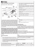
4. CIRCUIT DESCRIPTIONS
4.1 CONTROL PART
This model carries out all of its controls by the use
of a microcomputer (IC 501). Modes and progtams
are selected by the key input supplied into the key
matrix circuit (Fig. 4-4), while the microcomputer
controls various sections such as mechanism drive,
circuit switch'over, and mute control circuits by
feeding command outputs into those circuits' The
display circuit is provided to indicate the music
program being selectedand REC, DOLBY NR, etc'
being turned on or off.
O POWER ON
When the machine is turned on, the built-in microcomputer is initiatized (Fig. 4-1) and is ready to re'
ceive inPut sent from the keY.
RAM is clôot€d
Input and outPUl
ports are sel
limor d6ta la set
KEY SCAN
Wslt for mlcrocomput€r lCSOt
to 3t6blli26
(thst
Chæk to s€ lf decks A and B ar€ in th€ STOP mod€
ll thev âro not in ths STOP
15.when th€ hoad bts. is lN)
mod€, low€r th€ hoâd b63e to put thsm in tho STOP mode
Th61 th€ ba.e is low i3 depctêd bv MODE switchôs S3Ot
(for m€chêôi9m on dack A) rnd S4O2 (lo. mschanlsm on
deck B) (Th€ swilch€3 6t€ ofl during the STOP mod€.)
Check 6nd 51or€ the TIMER
RÊC k€Y stôtus in the
Statu3 ol llMÉR
REC koY i3 sto.6d In
thâ m9mory
QUESTIONNAIRE
MODEL
One Model per questionnaire
Dear Servicer,
Thank you for your cooperation in the post-salesenriceof Pioneerproducts.
This questionnaire is used as a tool to improve the serviceability of our products and servicemanuals.
Please evaluate this model and service manual by answering the following questions. Your ideas may be
realizedin our future products. Your answerswill be appreciated. Thank you.
PIONEER ELECTRONIC CORP.
T. Nakagawa,Manager, Service Section, lnternational Division
1. SERVICING EVALUATION
Circle applicablenumber:
a. Disassembly/Re-assembly:
b. Circuit Checks:
c.
Replacementof Parts:
d. Adjustment (s):
f If (4) or (5) was circled, please be specific.
Good
FaiI
Poor
e. Your advice, opinion or ideas related to senricingthis product.
SERVICE MANUAL EVALUATION
Circuit & Mechanism Description
b. Circuit Diagram
3. OTHER
Pleasedescribe other areasof servicing which you may find difficult.
Completed by :
Date:
Company Name :
Address :
CitylStatelZip:
Pleasesend this form filled to the dittribrtot
ir yo.r
"outty.
rê
$
1. SPECIFICATIONS
System ..........
4 t r a c k , 2 - c h a n n e ls t e r e o
H e a d s. . . . . . . . . . . . . . . . . . . ". H a r d P e r m a l l o y "r e c o r d i n g / p l a y b a chke a dx 1
" H a r d P e r m a l l o y "p l a y b a c kh e a d x 1
"Ferrite" erasing head x 1
MISCELLANEOUS
D u m m y e r a s i n gh e a d x 1
M o t o r .... . . . . . . .
. . . . . D C s e r v om o t o r x 2
Wow/Flutter
N o m o r e t h a n 0 . 0 7 o l o( W R M S )
No more than +0.20% (DlN)
F a s tW i n d i n gT i m e . . . . . . . . . . . . . . . . . . . . .A. p p r o x . 11 0 s e c o n d s( C - 6 0t a p e )
Frequency Response
-20 dB recording:
N o r m a lt a p e
. . . . . . . . 3 0 t o 1 4 , 5 0 0H z
( 3 5 t o 1 4 . 0 0 0H z + 3 d B )
C h r o m er a p e . . . . . . . . . . . . .
3 0 t o 1 5 , 5 0 0H z
( 3 5t o 1 4 . 5 0 0H z )
M e t a lt a p e
. . . . . . . . . .3 0 t o 1 6 , 0 0 0H z
{ 3 5 t o 1 5 , 0 0 0H z + 3 d B )
S i g n a l - t o - N o i s eR a t i o
DolbyNROFF..............
MorethanSTdB
Noise Reduction Effect
DolbytypeBNRON
...Morethanl0dB(at5kHz)
Dolbytype C NR ON
... More than 19dB (at 5 kHz)
HarmonicDistortion
. . . . . . . . . N o m o r e t h e n 1. 0 o l o( 0 d B )
Input (Sensitivity)
L I N E( I N P U T )
. . . . . . . . . . . . . . . . , .m
90
V
( l n p u t i m p e d a n c e8 3 k Q )
O u t p u t ( R e f e r e n c el e v e l )
H B model
HEM model
Power consumotion
KU, HEM and HB mode|s.......,.,,
(ourPUT)
LINE
""'
Power requirements
KU model
17wa11s
( W ) x 1 0 2( H ) x 3 1 4 . 5( D ) m m
..........42O
1 6 - 9 /1 6 ( W ) x 4 ( H ) x 1 2 - 6 11 6 ( D ) i n
........ 5.5 k9 l12lb 2 ozl
Weight (without packaging)
Dimensions
F U R N I S H E DP A R T S
O p e r a t i n gi n s t r u c t i o n s
C o n n e c t i o nc o r d w i t h p i n p l u g
Cottonswabset...............
.. . . . . . . . . . . I
. . . . . . . .2
. . . . . . . .. . ' l
NOTES:
1 Reference Taoes:
Normal and LH: DIN 44513/BLAÏTO or equrv.
C r O 2 D I N 4 5 5 1 3 / B L A T T T { C r O 2 )o r e q u i v .
2. R e f e r e n c e R e c o r d i n g L e v e l : - 1 0 d B v l e v e l a t l i n e o u t ( 1 6 0
nwb/m magnetic level = Philips cassette reference level)
R e f e r e n c eS i g n a l : 3 1 5 H z
4 . Wow and Flutter: . JIS 13 kHz, with acoustic compensation
( w e i g h t e d ) r m s v a l u e l ; D I N 1 3 , 1 5 0H z , w i t h a c o u s l i c c o m p e n s a tion (weighted)PEAK value DIN 45507
5 . F r e q u e n c yR e s p o n s e :. M e a s u r e da t - 2 0 d B l e v e l , D O L B Y N R
O F F , l e v e l d e v i a t i o ni s + 6 d B w i t h o u t . i n d i c a t i o n .
S i g n a l t o N o i s e R a t i o : . M e a s u r e da t t h e t h i r d h a r m o n i c d i s t e r t i o n 3 % l e v e l ,w e i g h t e d ( D l N 4 5 5 1 3 / B L A T T T ) .
7 . Sensitivitv: Input level (mV) required for reference recording
l e v e lw i t h i n p u t ( R E C )l e v e l c o n t r o l s s e t t o m a x i m u m .
R
M a x i m u m A l l o w a b l e I n p u t : W h i l e d e c r e a s i n gs e t t i n g s o f i n p u t
( R E C )l e v e lc o n t r o l s a n d i n c r e a s i n gl e v e la t i n p u t j a c k s , t h i s i s t h e
m a x i m u m i n p u t l e v e l ( m V ) a t t h e p o i n t w h e r e r e c o r d i n ga m p l i f i e r
iorrr"i,".,o"o"";;i:;
[T
SUBFUNCTIONS
.
.
o
e
.
o
o
.
o
r
o
.
o
.
.
.
A C 1 2 0V , 6 0 H z
. . . . . A C 2 ' 1 0V . 5 0 / 6 0 H z
... AC220V,50/60 Hz
One-touch recording
B u i l t - i n D o l b y B / C t y p e n o s i e r e d u c t i o ns y s t e m
Full electronic auto-stop mechanism
l C - b a s e df u l l l o g i c c o n t r o l
Automatic tape selector function
Relay play function for continuous playback
Tape copying function (From Deck A to Deck B)
Pitch control function (Deck A)
M u s i c s e a r c hf u n c t i o n ( D e c k A a n d B )
Timer standbvfunction (Deck B)
RECmuting function
Automatic level control
Direct program search{Deck A)
Programmemory skip {Deck A)
P r o g r a mq u i c k s k i p ( D e c k A )
Random aulo edit (From Deck A to Deck B)
output wave form becomes clipped.
Reference Output Level: -'10 dBv level at line out during
playback.
1 0 . T h i s m o d e l d o e s n o t e m p l o y a r e c o r d i n g / p l a y b a c kc o n n e c l o r
(DlN-type).
NOTE:
Specifications and the design are subiect to possible modifications
without notice due to imDrcvements.
This equipment generates and uses radio frequency energy and if
not installed and used properly, that is, in stricl accordance with the
manufacture's instructions; mav cause interference to radio and
television reception lt has been type tested and found to comply
w i l h t h e l i m i t s f o r a C l a s s B c o m p u t i n g d e v i c e i n a c c o r d a n c ew i t h
t h e s p e c i f i c a t i o n si n S u b p a r t J o f P a r t 1 5 o f F C C R u l e s , w h i c h a r e
designed to provide reasonable protection against such interference
i n a r e s i d e n t i a li n s t a l l a t i o n .H o w e v e r , t h e r e i s n o g u a r a n l e et h a t i n l e r f e r e n c ew i l l n o t o c c u r i n a p a r t i c u l a ri n s t a l l a t i o n .l f t h i s e q u i p m e n t
does cause interference to radio or television reception, which can
b e d e t e r m i n e db y t u r n i n g t h e e q u i p m e n t o f f a n d o n , t h e u s e r i s e n couraged to try to correct the interference by one or more of the
.
.
.
.
reorient the receiving antenna
relocate the cassette tape deck with respect to the receiver
move the cassette tape deck away from the receiver
plug the cassette tape deck inlo a different outlet so that the
cassette tape deck and receiver are on different branch circuits.
l f n e c e s s a r y ,t h e u s e r s h o u l d c o n s u l t t h e d e a l e r o r a n e x p e r i e n c e d
r a d i o / t e l e v i s i o nt e c h n i c i a nf o r a d d i t i o n a ls u g g e s t i o n s .T h e u s e r m a y
f i n d t h e f o l l o w i n g b o o k l e t p r e p a r e db y t h e F e d e r a lC o m m u n i c a t i o n s
C o m m i s s i o nh e l o f u l .
"How to ldentify and Resolve Radio-TV Interterence Problems"
ï h i s b o o k l e t i s a v a i l a b l ef r o m t h e U S G o v e r n m e n t P r i n t i n g O f f i c e ,
Washington, O. C -, 2W2, Stock No. 004-000-00345-4.
j followinSmeasures:
The above instructions apply only to units which will be operated in the United States
3. BLOCK DIAGRAM
FOR MS
c r R c u r ls I
B.
r
E
lol
; orr
Eton
MUTING TRANSISTOR
ERASE HEAD
St
o"
p,o"
O E C KA
MECHANISM
ASS'Y
Sl-56
g1-MB
D É C KA
-=
D E C K8
ffi"'flll@p..,,"
C U T ES W T T C(H. / o l
@ R E C / R EM
This switch functions as both the recording switch and record
muting switch. When pressed, the unit is set to the recording mode
and when it is kept pressed during recording, it functions as the
recording mute switch.
Recording switch
Press the switch when recording sound onto the tape. The
R E C / M U T E i n d i c a t o r n o w l i g h t s . l f t h e a c c i d e n t a le r a s u r ep r e v e n _
tion tabs on the cassette shell have been broken out or the taoe has
nol been loaded, the unit will not be set to the recording mode even
i f t h i s s w i t c h i s p r e s s e d .P r e s st h e S T O p s w i t c h ( r l t o
r e l e a s et h e
r e c o r d i n gm o d e . .
Recordingmute switch
W h e n t h i s s w i t c h i s p r e s s e dd u r i n g r e c o r d i n g , u n r e c o r d e d b l a n k s
can be created for as long as the switch is kept pressed. While kept
p r e s s e d ,t h e R E C / M U T E i n d i c a t o rw i l l f l a s h r a p i d l y . U s e t h i s s w i t c h
for efficient editing of tapes with sufficient blanks between the orog r a m s a n d f o r p r o v i d i n g t h e u n r e c o r d e db l a n k s w h i c h a r e r e o u i r e d
t o o p e r a t e t h e m u s i c s e a r c hf u n c t i o n .
This switch does not lock and so functions onty while it is kept in
the prcssed position. When pressed during a recording, no sound
is recorded and so the switch should not be pressed unless absolutelY necessary.
@ T | M E R R E CS W T T C H
T h i s s w i t c h i s u s e d w h e n a n o p t i o n a la u d i o t i m e r i s u t i l i z e df o r u n a t tended recording.
T i m e r r e c o r d i n gi s a f u n c t i o n o f D E C K B . D E C K A c a n n o t b e u s e d
1orttmer recordtng.
NOTE:
The timer switch should always be in the OFF position when not
performing timet recoding. lf a cassette tape is insened and the
switch is set to the REC position, the unit will automaticalty enter
the recording mode whenever the power switch is turned on.
@
*DOLBY NR SWTTCH
{ D O L B YN R O N / O F F )
Depressthis switch to ON for recording with the built-in Dolby
Noise Reduction system and for playback of tapes which have been
recorded using the Dolby Noise Reduction system.
Fof other tapes, do not press this switch.
*Noise reduction manufactured under license from
Dolbv
L a b o r a t o r i e sL i c e n s i n gC o r p o r a t i o n .
"Dolby" and the double-D symbol are trademarks of Dolby
L a b o r a t o r i e sL i c e n s i n gC o r p o r a t i o n .
SWTTCH
@ D O L B YB / C S E L E C T O R
( D O L B YN R B / C )
This deck is equippedwith both type B and type C Dolby noise
reduction
Afterthe DOLBYNRON/OFFswitchis pressed.
systems.
selecttypeB or C usingthisswitch.The Dolbyindicator
corresponding to the switch positionlights.
(
@ ) C O P YS W I T C H( B . A )
"Copying" refers to the process of transferring the recorded contents on a pre-recorded tape onto another tape. The pre-recorded
tape is loaded into Deck A and its contents are recorded onto Deck
B . W h e n t h e s w i t c h i s p r e s s e d ,t h e R E C / M U T E i n d i c a t o rw i l l f l a s h
sfowfy. Tape copying cannot be peéormed from Deck g to Deck A.
The playback tan
loaded into Deck B. When this switch is pressed, Deck A is
a u t o m a t i c a l l ys e t t o t h e p l a y b a c km o d e a n d D e c k B i s a u t o m a t i c a l l v
set to the recording mode, and the tapes start 10 move
simultaneously.
@ R E L A YP L A Y S W T T C H( B : A l
Press this switch for relay play. When pressed, the program indicators "1" and "8" will light alternarely. When the tape loaded in
one deck has finished playingand the tape comes to the end, the
tape in the other deck automatically starts playback. Relay play is
possible from Deck A to Deck B and vice versa
@ P|TCHCONTROL
This can be used to vary the tape speed of Deck A across a + 60Â
range. The speed increases when the control is rotated clockwise
( f) ) and reduces when rotated counrerclockwise ( Ô ); rhe
musical intervals are made higher or lower, respectively. The stand a r d s p e e d i s o b t a i n e da t t h e c o n t r o l ' s c e n t e r c l i c k s t o pp o s i t i o n( y ) .
Use the control to adjust the speed when adjusting the intervalswith
m i x i n g r e c o r d i n go r p l a y b a c k o r w h e n p l a y i n g b a c k a t a p e r e c o r d e d
on another tape deck on your own deck.
NOTE:
Set this control to the clickstop position (f ) when using the
music search function. lf it is left rctated clockwise, it will not be
possible to detect the unrecorded blanks between the programs
on the tape during fast forwarding or rewinding operations.
I
|lakr:sToP
t |lul/.:ll|lP
.,
E?f.$i'
DECK A
,rorI-81
I
LIilE OUT
FOR US
ciRcutr s2
DECKB
ts
R/P HEAO
T
STOP
Sl -S6
ELECTRTCSWITCH
[6-61 : o"
LINE IN
I:o*
ilU.fING 1RÂNSISTOR
'
F:
o"
on
P-t
L sl
ASOL2
ÀsoL I
I
MUTE BSOL 2
L S2
BSOL I
LINE
XUTE
L;;
KEY
SCAN
I *s.su
coev,1fl,,
*-*:t
BIAS
ii?. "f3"
LMI
+
P U L Lu P ( + l 2 v )
--@"'@
,,)t2
n M4
L M7
(5304 ând-S305)
"ON" with NORMAL Epe
'.Ëïr'l *nn a,O, and METAL tape (5304 and s305)
TSI
|
----
' - - - - -rl7- - - - - - - - )
Fig, 4-6
Signatroute 1
I
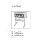
4 . 3 S I G N A LB O U T E S
Dependingon the modesselectedon decksA and
FUNCTION
D E C KA
D E C KB
COPY
SWITCH
C O N T R O LP A R T SO U T P U T
S1
S2
53,55 54,56
1
STOP
STOP
OFF
L
.I
L
2
STOP
STOP
ON
H
.
L
3
PLAY
STOP
4
STOP
PLAY
5
STOP
BEC
b
PLAY
REC
H
ll
S7
M1 M2,M4 M3
M5
M6
M7
H roNi
L
H
H ]
u
H
L
H
H
L
L
L
H
H
i
LLHONLHLHHL
OFFi
HLHONLHLHHL
L
L
H
.t
L
I
H
L
OFF1 H
L
H
H
L
H
H
L
OFFI
L
L
H
L
H
_
H
i
l f c o P Y s w i t c h i s t u r n e d o N w i t h b o t h d e c k sA
a n d B i n S T o P m o d e , i t c a u s e sd e c k s A a n d B t o b e
set in pLAy and BEC
m o c t e sr e s p e c t i v e l yr,e s u l t i n gi n d i f f e r e n t s i g n a lr o u t e s .
DECKA I
FFor REW I
STOP
FF
Oecxe
SfOp
I FFor REW
I
FF
REW I
rt
E g u a li n s t a r u st o b o t h d e c k sA
a n d B s e t i n S T O Pm o d e .
REW
rr
MS
Fis.4-5
tl. Dec[
B: STOP
 : SIOPDeck
oEcKa
fl
r"n -5?f.$Pt
FOR MS
DECK 8
t
t^l
STOP
tI l f'\
ctRcutrs2
R /P HEAO
l\-,,1|
lr',1I
lvl
LINE OUT
r::.:71
t.ffil
I
EL€CÎRIC SWITGH SI-S6
LINE IN
16l
; orr
Iton
MUltitG
TRANSISTOR
F
i orr
i ox
)
L St
ÀsoL2
ÂsoL I
L s2
BuuTE B soL 2
BSOL I
53
-t s 5
Lra
,- ,ss64
1*t.uu
coPY H;TÀrx
q527
'"""'oït
+
MUIE
/ PE
LMI
P U L Lu P ( + t z v )
--@"*-@
,,)t2
n M4
LM7
r2v
q 3 rI
TSI
------]
rI - - - -
S3O4 +F
t.-
i-\---i
L--1\?<_---
^#
'
'
|
s4o5 rL
DECK A
I
MEcHaNlsMrss€ualY I
B
DEcK
"ON" wilh NOBIVIALtâpe (5304 and 5305)
"OFF" with CrO, and l\4ETAL tâpe (5304 and 3305)
I
aSSEMBLY
MEcHaNrsM
i
I
Fig.4'6
S i g n a lr o u t e 1
rc 501
rc 502
I
aPo
Pl
I
cP2
P3
P4
$
eur-ruP RESrsroRos2e (oE:l1l
D2t3
PL^Y
//
o.s.3r,rr3l"^i;
D533
,or"trIr(
S T O P/ /
I
C OP Y
MOOE
5301
szt8 - 4
ENO
s 302
s2r8-t I
HALF
s 303
END
s40 |
MOOE
s402
s 403
Fig. 4-4
Key Matrix Circuit
s2r8-5
I
Ch€ck to 3@
I' TIMEFI
REC k€y is
ON or OFF
REC LEO
(O) liOhB up.
Reâdy to rsc6iva k€V Input
It 5c6ns th€ k€v oporatlon and
æcordlngly.
cauæs furctlon
Check tho TIMER REC key
slor€d in th€
rtats (oN/oFF)
m€mory, It ON, tho unit 13tn
th€ REC mode
ls FIE LAY
switch ON?
Fig.4-l
I
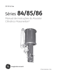
4.2 KEY MATRIX CIRCUIT
The key matrix circuit, composed as in Fig. 4-4,
sends scan pulse to control the mode input for
decks A and B as well as program selection input.
The scan pulse decodes outputs from pins L4,75,
and 16 on the microcomputer, sending 10 m sec
pulse from pins 1 through 5 of IC 502as shown in
Fig.4-2.
This pulse, in turn, is fed into one of the pins 17
through 22 of.IC 501 as the key matrix input corresponding to the key input, thus allowing the
microcomputer to send output signals matched
with key inputs to each section.
Control ScanPulse
P2
P3
P4
L
H
H
H
H
FI
L
H
H
tl
l-l
H
L
H
H
A
Po
o
o
I
o
I
o
o
I
I
Fis.4-2
Pr
B
o
o
H
H
H
L
H
o
t
,a
H
H
H
L
F i 9 .4 - 3
2. COPYswitchON
FOR MS
c r R c u r sT2
I
_.1|
-, 1
_l-J
1
M8
; orr
lZl
Ito*
MUTINGTRÂNSISTOR
ai
)
:
oFF
i
on
Q53/
L52
MUTE 8 soL 2
soLENOr0
DRIVE
C l R C rt T
ESOL I
LiME
MUTE
. s5
KEY
scÂN
's6
KEY
M Â T RI X
CIRCUIT
coot nriT*,"
FOR HEAo+r
I *ssu
BIAS
st \? ll
oFF 1'
REC
MUTE
REC
/ P8
aà\
* fi)
\-{
H2
l - 1M 7
TSI
ON
wLIh NORMAL
OFF
F i g .4 - 7
S i g n arl o u t e2
rape rS304 ând5305
w rh CrO: and METAL
rdpe rS3O4 dnd S3O5r
./-\
oR'ft(
\:r/
)
5. DeckA : STOP DeckB : REC
DECKA
Rch-
P.8 HEAo
''o,l3l
t v t 3il19
,t
r-t
F
+CtRCUtr
,lÆ
rh
;br
'f
*'
FOR MS
crRcurrs2
| 1--\
l-:-]
r---^ --
LINE OUT
!
ll
REC
rJ
I
LINE
M8
ELECÎRIC SWITCH SI-S6
: oer
lol
Ito"
HUTING TRANSISTOR
P
)
:
oFF
i
on
Q53r
L Si
ASOL2
-A-S- O
- 'L I
B
MUTE B SOL 2
SOLENOID
ORIVE
CIRCUIT
BSOL I
LINE
MUTE
-, ,ss53
KEY
SCAN
HM3
+ t2v
LM8
t-'
o 527
.ôoY
--
I *s.sv
KEY
MÂlRtX
MUTE
/PA
+
PULL
uP(+rzv)
--@""@
t---I S 3 O 4+ B
F\J
Y
rsz$
D E C KA
i
I
MEcHANTsM
asseàlaLv
-
L-----
, saos
"|'
------
J
D E CIK
i
lsseuar-v
MEcHANtsM
!
Fig.4-1O
"ON" with NORMAL rape (5304 and 5305)
"OFF" wûh CrO, ànd METAL râpe 15304and 5305)
S i g n a lr o u t e 5
3. DeckA:PLAY
DeckB : STOP
(
I r'.-
|
T:::::---- r---::---:-----------
rl
r-i
I
M8
E L E C T R TS
CW T T C HS t - S 6
lo3 ; orr
to"
f
M U T I N GT R Â N S I S T O R
D,0,,
)t
o"
Hst
MUTE A SOL 2
,sol
^
I
MUTE I SOL2
ESOL I
LINE
MUTE
L::
KEY
S C AN
' ' Ss s4
'-''
KEY
MATRIX
XEY
MÂTR
IX
CIRCUIT
BIAS
-ue
,
efF
Hus
I
,
REC
lfurE
I
REC
/ Pa
Ic5ol
M2
,L, )M a
Luz
TS i
I
t3oo ..g
D E C KÂ
'ON'wrth NORMAL
t a p e ( 5 3 0 4a n d 5 3 0 5 )
'OFF"
wrrh CrOl and METAL lape 15304and 5305)
Fig.4-B
Signalroute 3
PULLUP(+12V)
aà.,o^/--\
- t5/
tg,)
I
4. DeckA: STOP DeckB : PLAY
DECKA
Rch
u."'8"ë,
D
+C;RCU;T
;pr
rr
Tst
FOR I,|S
crRcurTs2
,r^"8
T
LINE IN
16-îl s orr
Lsr
A
iIUTE
A SOL
Hsz
asoL I
g
MUTE B SOL 2
. s3
ts5
LINE
ilUÏE
ESOL I
,t ,ss64
XEY
SCAN
LM8
o52?
KEY
MATRIX
c r R c u| 1
I *s.su
-çF
-@.'@
LMI
,,t 2
n M4
L M7
q3l I
TSI
rI - - - -
S3O4 +B
+*\J
"' H
P U L Lu P ( + t 2 v )
J-l
s4o5 ,ç
-----]
DECK A
I
MEcHANTsM assEMBLY I
(5304 ând S3OS)
"ON" wirh NORMAL tapê
and 5305)
*'.n c,o, and METAL rape ls3o4
"ôit"
:.'-'-i..:
^...^^-..^
aSSEMBLY
MECHANTSM
i
L___________-J
Fig. 4-9
Signal route 4
6. DeckA:PLAY
DeckB:REC
FOR MS
DECK A
c r R c uTf s r
P.B HEAO
,,r^"8
h,
O E C KB
FOR MS
-.,tq
--
crRcurT
s2
R,/p HEAD
I f:--=-
T
[*P--l l-ji,.s,,,RI !
; or.
lol
Ito*
tr
I orr
l
I otr
HSr
ÂsoL I
B
MUTE 8 soL 2
B S O LJ
LIN€
-s5
f M3
s4
LM8
o 527
.ôpY
--. .
KEY
MÂTRIX
I +5 5V
Elas
-çREC
I'UTE
REC
/ PA
PULL UP I+ IzV}
/'Al
x ff)
v
ri - - - -
s3o4 .a
1<\_J
I
oEcK a
I
MEcHANTsM
asseuerv I
"ON"
wtrh NORMAL
"OFF"
F i g .4 - 11
S i g n arl o u t e6
wrrh CrO.
rape {5304 and 53051
taoe (5304 and 5305/
and METAL
/-\
o n{ * { )
\:t/
o lC TECHNICAL DATA
PD3012
No.
SYmbol
vo
Name
DEsription
GND
Vss
vs3
RES
RES
INT
INT
External interruot/PowER
9
X TAL
X TAL
4.0MHz Crystal resonatot
6
EX TAL
EX TAL
1
NUM
NUM
I
TIMER
TIMER
9
c0
REC MUTE
Deck B Rec mute output,
L level lurns REC mute ON
LINE MUTE
Line mute outpul.
L lwel turns LINE mute ON.
Signal route change output.
L output during COPY mode; H otherwise.
1
Reset
IN
OFF causes L (This automaticallv leads 10 STOP mode).
+5.5V
4
IN
10
GND
11
c2
COPY
r2
c3
RÊC INO
r3
u
MS
14
c5
Norm€lly at H.
OUT
16
c7
17
D7
18
D6
1g
D5
LEO drive oulput
*2
Deck A lime constant switch output du,lng music search H during MS mode.
Cs-C7
ourpût
KEY SCAN
15
Oeck B ræording
Po-P4
oulputs
Po
KEY MATRIX
IN
PI
Lf---Lf_
t_l
rN
L_
----l-J-
20
o4
t'
21
D3
Pr -----------.1 f_ u D--------l_f
6
'"
22
D2
23
D1
BMS
24
DO
AMS
;;
Ds
D?
Deck B MS oulse delætion terminals:
deted L MS pules,
Deck A MS puls delætion te.minâls:
detæt L MS pulses.
L lights up LED.
'2
25
BO
M Ê M O F YL E D S
Memory display LEO d.ive oulput (No.8);
26
B,I
M E M O R YL E D 7
Memorv display LED drive outpul lNo. 7);
L lighls up LED.
'2
27
M E M O B Y L E D6
Memory display LED drive output (No, 6);
L lighls up LEO
'2
,82
2A
D3
M E M O F Y L E D5
Momory display LED drive output (No, 5l;
L lights up LED
'2
29
B4
MEMOFIY LED 4
Memory display LED driv€ output (No 4);
L lights up LED
'2
Memo,y display LED d.ive output (No 3);
L lights up LED.
'2
(No. 2);
L lighrs up LEO.
*2
Memory disptay LED drive output (No. 1);
L lighls up LED
30
B5
MEMOFY
31
B6
M E M O R YL E D 2
32
87
M E M O R YL E D 1
33
AO
BIAS
g
A1
35
36
LEO 3
Memory disptay LEO drivo output
OUT
Deck B bias OSC ON/OFF output:
L lturing REC mode.
R E C/ P B
Deck B BËC/PB switch-over output:
H during REC mode.
A2
B MUTE
Deck B signal route switch.over:
L during PLAY on Deck B
A3
A MUTE
Deck A signal roule swilch-over:
L during PLAY/COPY on Oeck A.
A4
ASOL2
Osck A Solenoid-2 drive pulse output:
L activated.
L activ€ted.
38
A5
A SOLl
Deck A Soleooid-l drive pulse output:
39
A6
B SOL2
Oæk B Solenoid"2 drive pulse slput:
L activaled.
A7
B SOLl
Dæk B Solenoid-l driva pulF outpul:
L activated.
40
'2
s*itch
l--------l[ T,ansisto,
fll
fiTaotuat
Læt.*itcn
switch
LEO lighted
Output
timing
LED tlashing slowly
LED tlashing fa$ly
Fig.4-14
DeckB:REC
6. D e c k A : P L A Y
FOR MS
crRcurTsl
"aOrE
OECKS
FOR MS
c r R c u r sT2
I f-=-
f,;;--l
l- oo.,'-G__.lI
rl
_t ll
-lJ
I
lol
; o.r
I
:oN
M U T I N G TRAI{SISTOR
\J}
I
orr
)
i
on
Hsr
I,IUTE Â SOL 2
DECK A
ÂsoL I
^
MUTE B SOL 2
OECX B
85oL I
LINE
HUTE
KEY
S C AN
ÂI + 5 5 V
coPY uiià't
8rÂs
F O RH E A D
z\OFF
-EREC
MUTE
ï
Hvr
REC
/ PB
aà
lus
' {+](,J
rcsol
*---I---------d
\-{
M2
- M4
H t47
TSI
PULL Up (+ 12v)
T--I S 3 O 4r â
D E C Ka
I
"ON
w,lh NORMAL
OFF
rs2
F i g .4 - l 1
S i g n a lr o u t e 6
tape (5304 ànd 5305)
wrth CrO: and METAL
tape lS3O4 and 53051
/-1\
on {*{)
\:t/
4.4 DIRECT MUSIC SEARCH
For direct search,the tape is first rewound completely in RE\{ mode. \ryith one of the search keys depressed, the tape is then fast-forwarded to the beginning of the program desired (the intervals between programs are counted during FF mode).
When the beginning of the wanted program is
reached, the tape is set in the STANDBY mode.
Depressing the PLAY key allows the program to
start. In this way, the desired progxam is automatically located for playback by depressingthe program No. key.
The direct music search mode allows desired programs to be played back in a desired sequence regardless of the order in which the proglams lvere
originally recorded (for the first program to be
played back, tape is rewound until the beginning of
the tape is reached; from the second progmm onward, direct search takes place). Moreover, the
sarne prograrn can be played back as many times as
the prognm No. key is repeatedly depressed(up to
16 times). When used for copying, this mode enables the desired number of progxams on the original tape to be dubbed in any desired sequence.
During copying, the non-recordedsectionsbetween
the programs being dubbed are automatically adjusted for a uniform interval (automatic random
editing).
4.5 MODE CHANGE IN THE MECHANICAL
SECTION
The mode selection for the mechanical section is
controlled by the output (pins 37 through 40)
from the microcomputer (IC 501) corresponding
to the key input. The output from the microcomputer turns on and off SOL 1 and SOL 2 of the
mechanical section, which trigger mode changes
with the po\Mer assist mechanism using the rotar5l
power of the capstan motor. The mechanical section changes its mode as shown in the Fig. 4-13,
and this always via the stop mode. The timing
chart in Fig. 4-15 shows the control signals for
different modes sent from the microcomputer.
. IC TECHNICALDATA
PD3012
No
Symbol
Name
r/o
,]
I
D e s c ri p l i o n
GND
2
RES
3
INT
INT
5
X TAL
X TAL
6
EX TAL
E X TAL
7
NUM
NUM
TIMEFI
TIMER
Fleset
HÈà
IN
E x t e r n a l i n t e r . u p t / P O W E R O F F c a u s e sL ( T h i s a u t o m a r i c a l l vl e a d sr o S T O p m o d e )
+5 5V
4
4 OMHZ Crvstal resonâtor
IN
10
GND
Normally at H
co
R E CM U T E
Deck B Rec mute output
L level turns FIEC mute ON
c1
LINE MUTE
Line mute outpul,
L l e v e lt u r n s L I N Ê m u t e o N
Signal route change oulpuÎ.
L output during COPY mode; H otherwip
c2
COPY
c3
REC IND
c4
MS
OUT
Deck B recording LED drive outpur '2
Oeck A time ænstant switch output during music se6rch H during MS mode
14
Cs-C1
oulpul
KEY SCAN
16
c1
17
D-7
l8
D6
'19
D5
Po-P4
outputs
KEY MATRIX
IN
20
D4
21
D3
I
:: rr---rr
,N
{
D1
26
:t
iÈ
30
detecl L MS pulses
Oeck A MS pule derætion rerminals:
detecr L MS gulses
AMS
BO
MEMORY LEDS
Memory displayLEO driveourput (No 8);
L l i g h t su p L E D
B1
MEMORY LED 7
Memory displav LED dilve ourput (No 7);
L l i g h t su p L E D .
'2
'2
IVEMOFY LEO 6
Memory displavLED driveoulput (No,6),
L l i g h r su p L E D
'2
D3
M E M O R YL E D 5
Memory displôyLED driveoutpul (No, 5),
L t i g h r su p L E D
'2
B4
MEMORY LED 4
Memory displav LED driveoutput (No 4);
L l i g h r su p L E D
'2
MEMORY LEO 3
Memory display LED driveoutput (No 3)j
L lightsup LED
'2
Memory display LEO drive output (No 2);
L lighrs up LEO
'2
Memory display LED drive ou1pu1 {No, 1 ).
L I'ghts up LED
'2
M E M O R YL E D 2
1a
Deck g MS pulse derætion terminals:
DO
27
2A
BMS
87
MÊMOFIY LED '
OUT
AO
BIAS
Oeck B biasOSC ON/OFF ourput:
L during REC mode
AI
REC / PB
Oæk B PËCIPB switch-over oùtputj
H dùring AEC mode
A2
B TJUTE
Deck B signal route switch-over:
L during PLAY on Deck B
36
A3
A MUTE
Deck A signal route switch-over:
L during PLAY/COPY oh Oock A.
37
A4
ASOL2
Deck A Solenoid-2 drive pulse outpur:
L activared
ASOLl
Deck A Solenoid-l drive pulse ourput:
L acrivaled
Ë
34
38
A5
39
40
A7
B SOLl
[-ll]
Transisto,s*;rch
l--[
LGk switch
flTaotual
s*itch
Oeck B Solenoid.2 d.ive pulse outgut:
L acrivâred
Dæk B Solenoid-1 drive pul6e output:
L activated,
LE O I ighted
Outpur
Irmrng
LED llashing slowlV
LEO flashing fastly
Fis. 4-14
D I R E C T P R O G R A MS E A R C H
lNô
ab.olut.
.#r...
tôl
ilowrv
LEO rl6h6
onw.rd
2nd prog..m
LED )'sht. cohnnuou.rv
LÊO rldnù r.rrlv
2nd o.d..6
ew.rd
LEO rr.$ô rrowrv
LEO
tl.rhd
tl@lv
Fi1.4-12
(&bluE
dr.$...19Â.d
tor
STOFI
o
l
Rq.@
N.rt
LEO
rogramSearchFlowchart
Fi4
LEO fi.ô6
groqrdm
6rcnôo:
f{ilY
to b
ltdhrrr,owry
Plâv'd
bæk
D I R E C T P R O G R A MS E A B C H
LEO rrdÀ6 noÉrv
onw.rd
2nd p.og..ô
!EO I'ehrr conr'nuôurlY
\
/<
X
LED
l--=-
f
_/
F.r
oI
or o.ogrF
I
II
I
t.
I
r.rr v
LEO irdh6
ônw!rd
2nd o.4r.6
LÉo rr.th.r iow
v
LEOrra!Àé
nùrv
Fis.4-12
bing.Étchd:
ftqÉm
LEO ll.ù6 fa.tlv
N.tt P69r.m o b Pl.Yêd bck
LED fla.ho srodY
gramSearchFlowchart
ffi,'
1
5. DISASSEMBLY
2
3
o
I
o
D"X
\/a
V
a-__
F r o n t p a n e lassemdy
@o
J
Complex
a s s e m b l y(
D
a
fq
v
3
I Drurunilu
1 ) Undo screw Q
to remove
the bonnet
case.
2) Remove screîv @ to dismount the stay'
3 ) For the removal of the bottom plate, re-
. u)
move screw O ot the bottom of the set'
This allows the soldering on the composite
assemblv(B) to come into view'
4) Removing rivet () and screw @ on the
,"a, pat"i causesthe P.C.B. holder to be unfastened, enabling DOLBYINR assembly
to be detachable.
The complex assembly (B) ^can be dismounted 6y removing screw @
6 ) Removing screw (D ut well as trgok @ on
PB support permits the power supply assembly to be dismounted. Then, the power
knob assembly can be removed from the
power supPlY assemblY.
the power supply assembly is removWttett
7')
ed, the transistor assembly comes into view'
Remove screws to dismount the transistor
assembly.
8 ) Undo screw @ ott its lower portion to remove the transformer.
e) For the removal of door panels A and B,
slide the panels upward with the doors kept
open.
10) To remove the front panel base,undo screw
(|
and slightly lower the panel stayhook
hookQ(lower
d-("pp"t four portions) and
i*o po*ions) using a flat screwdriver, etc'
11) The tape counter is removed by removing
scïew (p .
tzl The panel stay is removed by removrng
screw O .
13) The display assembly is remored by removing the panel stay hook (without having to
remoue ihe front Panel assemblY)'
14) The push and PC knobs are detachable
from the display assembly when the latter
is removed.
15) The eject knob is removed by removing the
hook on the back of the Panel staY'
16) Remove scïe\il @ to dismount the cassettE mechanism unit (the removal of the
power knob assembly enables the mecha'
nism unit to be dismounted without requiring the front panel assembly to be removed).
@,,
5. DISASSEMBLY
2
3
o
A
I
f
r
q
à
Y
Door panel B
Door panel A
D
I Disasembly
1 ) Undo screw O to remove the bonnet case.
2 ) Remove screw @ to dismount the stay.
3 ) For the removal of the bottom plate, re-
.u)
move screw (O ot the bottom of the set.
This allows the soldering on the composite
assembly(B) to come into view.
4 ) Removing rivet @ and screw @ on the
rear panel causesthe P.C.B. holder to be unfastened, enabling DOLBYINR assembly
to be detachable.
The complex assembly (B) can be dismounted by removing screw @
well as hook @ on
6) Removing scre\ry (D
"t
power supply aspermits
the
PB support
Then, the power
be
dismounted.
to
sembly
knob assembly can be removed from the
po\Mersupply assembly.
7',) When the power supply assembly is removed, the transistor assembly comes into view.
Remove screws to dismount the transistor
assembly.
8) Undo screïv G) ott its lower portion to remove the transformer.
e) For the removal of door panels A and B,
slide the panels upward with the doors kept
open.
10) To remove the front panel base,undo screw
and slightly lower the panel stayhook
L
(D(upper four portions) and hookQ(lower
two portions) using a flat screwdriver, etc.
11) the tape counter is removed by removing
screw lE .
L2\ The panel stay is removed by removing
screw O .
1 3 ) The display assembly is removed by removing the panel stay hook (without having to
remove the front panel assembly).
14) The push and PC knobs are detachable
from the display assembly when the latter
is removed.
1 5 ) The eject knob is removed by removing the
hook on the back of the panel staY.
1 6 ) Remove screw @ to dismount the cassettE mechanism unit (the removal of the
porver knob assembly enables the mechanism unit to be dismounted without requiring the front panel assembly to be removed).
TimingChart
OPERATIONKEY INPUT (DECK
MECKA MECHANICALMODE
STOP
PLAY
O E C K8 M E C H A N I C A LM O D E
STOP
S T OP
DECK B
BsoLr @
MECHANEAT
BSOL'@
CONTROL
D E C KA
MECHANICAL
CONTROL
asoLre)
H
a
MUTIN6
CONTROL
B MUTE
necz e.a @
BI A S
MS
I N O I C A TI O N
CONTROL
S I GN A L
ROUTES
a
MUTING
CONTROL
@
@
@
-rruo
nEc
@
C OP Y
1ô
mE-ilur @
STOP
)
IUH
REW
S T OP
S T OP
STOP
H
H
@
S TOP
STOP
H
-^
asoLrQ9
A MUTE
SI G N A L
ROUTES
FT
H
u
ril
J
:f
r2
;E-rr
j
-r3
F',
H
L
H
t{
H
-
r+ --l
nec uuïE @
OPERATIONKEY INPUT(DEC
PLAY(B)
FF (B)
REW(B)
STOP(B)
REC(B)
PLAY(A)
STO
a soL2 @
a murE @
B xurE @
Bras
@
INOICATION
CONTROL
Fig.
ël
Tl=lOOms
T2-- 2OOms
T3 = 7OOm3
T4 = SOOms
STOP(AorB)
COPY
'iming
Chart
( PLAY)
(REC)
3
7. EXPLODED VIEW AND PARTS LIST
7.1
o
A
I
B
I
D
I
MAIN
@.-39
2s{|-
+t4
29
\
D!
28
llrr
/}-29
29
6. PARTS LOCATION
NO?'ES;
o Parts without part number cannot be supplied.
o The S mark found on some component pafts indicates the
importance of the
safeû factor of the part. Therefore, when replacing, be sure to useparts of identicol
designation.
t For your Parts Stoeh Controt, the fost mouing items are indicated
with the marhs
** and *.
**
GENERALLY MOVES FASTERTHAN *.
This claæification shall be adiusted by each distributor becauseit depends on model
number, temperature, humidity, e tc.
Front PanelView
Front panel assembly
ANM649
Bonnet case
ANE489
Knob A (PLAY)
AAO-822
Knob A (PLAY)
AAD-822
Knob B (STOP)
AAO-823
I
Door panel B
ANR.843
Knob B (STOP)
AAD.823
'+fl:
*
Eject knob
AAD-835
Ooor panel A
ANR.842
Eiect knob
AAO-835
Power knob assembly
AAD-836
K n o bD ( R E W I
AAO-825
K n o b E ( R E C / R E CM U T E )
AAD-826
K n o bD { R E W }
AAD-825
tary knob
( P I T C HC O N T R O L }
AAB.372
Rear PanelView
V a r i a b l e r e s i s t o r( R E C V O L U M E )
ACT-191
'{
4P pin jack (REC,PLAYI
AKB.O94
I
Strain retief
AEc-327
Power cord
ADG-052
Front View with Panel Remoted
LED (RED}
AEL.382
*
Tapecounter
AAW.I39
\
* LED (GREEN}
AEL424
K n o bC ( F F l
AAD.824
Knob C {FF)
AAD-824
Cassetteplate
AXR-o11
Cassette plate
AXR{1 1
ff
Erasehead
APB.OOS
*
**
head
*REC/PB
APB.OOT
ffPin
Pincharm
AXP-O22
PB head
APB006
Dummy head
AXNOl6
arm
AXP-O22
Pushknob
AAD.894
Tactualknob
AAD-834
Top View
* eo*er transformer(120V
ATS.122
[
[
*t
A ff
A
ruse (2A]
AEK.122
powerswitch {stol
ASG-541
Powersupplyassembly
GWR.206
DOLBY NR assembly
GWY-130
tf
Ps66 relay (RY301l
AsR-o74
assemblv(Bl
AWM.629
rc ilc501)
PD3012
)
2
7.3
MECHANISM
A S S E M B L Y( D E C KB }
I
A
t
I
B
o
-12
-@
@
4''e
D
a
2
3
4
5
o
A
26
1.."J
43
38 82
PartsList of Main
NO?ES:
o Parts without part number cannot be supplied.
o The I
marh found on some component parts indicates the importance of the
safety factor of the part. Therefore, when replacing, be sure to useparts of identieal
designation.
r For your Parts Stock Control, the fast mouing items are indicated with the marhs
** and *.
**
GENERALLY MOVES I'/S?E^R THAN *.
This classification shall be adjusted by eoch distributor becauseit depends on model
number, temperature,humidity, e tc.
Mark
No,
Part No.
Description
GWR-206
GWY-129
GWY.130
AWM.629
ATS-122
Powersupply âssembly
Displayassembly
DOLBY NR assembly
C o m p o s i t a s s e m b l y( B )
P o w e r t r a n s f o r m e r ( 12 O V )
101
102
103
104
105
M e c h a n i s mu n i t ( D e c k A )
M e c h a n i s mu n i t ( D e c k B )
Main chassis
Bottom plate
PCB holder
8
9
10
AEK-122
AEC-744
ANM.649
AAD-834
AAD-835
Fuse (2A)
Foot assembly
Fronl panelassembly
Tactual knob
Eject knob
106
107
108
109
110
Stay
PB supporter
T r a n s i s t o ra s s e m b l y
Front panel base
Indicator panel
11
12
13
14
'15
AAD-822
AAD-823
AAD-824
AAD-825
AAD-826
Knob A
Knob B
KnobC
Knob D
Knob E
111
Front panel stay
16
17
18
19
20
ABH-136
A B H -1
I 2
AAW-I39
PBZ26P060FMC
AAB-372
Spring
Spring
Tape counter
Screw
Rolary knob (PITCH CONTROL)
21
22
23
24
25
AAD-836
AAD-894
ANE-489
ANR-842
ANR-843
Power knob assembly
Push knob
Bonnet case
Door panelA
Door panel B
26
27
2a
29
30
AEC.327
ASG.541
ADG-052
BBZ30P080FZK
vBz40P060FMC
Strain relief
P u s hs w i t c h ( P O W E R ,S 1 0 1 1
Power cord
Screw
Screw
31
32
33
2SD1406
AKB-Og4
ACT-191
34
35
AXR-011
AXW-008
T r a n s i s t o r( O 4 O 1 )
4 P p i n j a c k ( R E C ,P L A Y )
Variableresistor
(REC VOLUME, VR107}
Cassetteplate
Counter belt
36
37
38
39
BBZ3OPOSOFMC
BCZ2oP120FMC
AWP.O19
ATZ26POSOFMC
1
2
3
4
A
*5
A
tr6
I
*
A
Aff
A
ff
(PLAY)
(STOP)
(FF)
(REW)
(REC/REC MUTE)
Screw
Screw
Control assembly
Screw
Mark
No.
Part No.
Deccription
7.2
PACKING
C
Para List of Packing
Mark
No.
1
'2
Part No.
3
4
5
AHA-379
AHG-I82
AHE-348
ADEO74
AEX{16
Pad
Bag
Packing case
Cord
Head cleaner
6
7
8
AHG-169
A H G - l1 7
ARB€10
Bag
Bag
Operating instruction
qD
I
I
7
r
-Ln
|
il
l;;
REC
- OTH
c.;=--;;-:-al
\5r\ tÀ.
'nlj
'
ô
:
I
J
:'
,
A
lÀ
, ,1
I
I
-
l:.." :'1. i6 ,
6 _ . tr
'
I
\
1 E ^ w /
I
lo
I
o
1P?
ro
DISPLAYASS'Y
G W Y- 1 2 9
T R A N S I S T OA
RS S '
rC')*\-":
I
I
o
}OL8YNR ASS'Y GWY-I3O
A
QgOi 2SCi74OS
o902 2SA933S
OgOi- 9O5 USlO35
CONTROLASSY
A W P- O t 9
TI
ATS-122
tl
tl
II
Dror RBr52
Dto2,1O4 55566
oto5 KzLr30
oto6 KzLo6{
POWERSUPPLYASS'Y
GWR-206
Assembly(DeckB)
PartsList of Mechanism
No,
Part No.
Description
AXS-055
AXV-060
AXS-056
AXT-OO7
AXS-O57
Elect lever
S p r in g
Gear
Bush
Reel pawl
7
8
9
10
AXV-061
AXP.O2O
AXS-058
AXV.O62
AXP.O21
S p r in g
Take-up reel base
C l u t c hp l a t e
Spring
Supply reelbase
11
12
13
14
15
AXW.O23
AXV.O63
AXP-O22
AXV.O64
AXS-059
Plate
Spring
Pinch arm
Spring
H e a ds t a n d
16
17
18
19
20
AXR.OOS
AXV-065
AXT-OO8
AXV.066
AXV.067
Stopper plate
Spring
Steel ball
S P r in g
Spring
21
22
23
24
25
AXR-011
AXS-060
AXV-068
AXV.O69
AX5-061
Cassetteplate
RECarm
S p r in g
Spring
Head stopper
26
27
2A
29
30
AXS-062
AXS-063
AXV-O70
AXS-064
AXV-071
Bush
ldler gear
Spring
Brakearm
Spring
31
32
33
* u
35
AXV-O81
AXT-009
AXW-024
AXW-025
AXP-024
Thrust plate
Screw
Shock mount
C a p s t a nb e l t
Flywheel assembly
36
37
38
39
40
AXSO65
AXW-026
AXS-066
AX5-067
AXV-072
Motor pulley
Belt
Worm
AS cam
S p r in g
41
42
43
44
45
AXP-025
AXV-O73
AXS-068
AXV-O74
AXS-069
Drive arm assembly
S p r in g
Sensor
S p r in g
S e n s o ra r m
46
47
48
49
50
AXV-075
AXV-076
AXS-o70
AXV-077
AXS-071
S p r in g
S p r in g
T r i g g e ra r m
Spring
Cam gear
51
52
53
AXV-078
AXW-007
AXW-008
Spring
O ring
Counter belt
1
3
4
5
Mark
ff
tt
*
ff
A*
A*
ff
*
*
ff
fi
ff
Part No.
Description
54
55
AXV-079
AXS-072
Spring
R e e l r e c e p t a c l eB
56
57
58
59
60
AXP-028
AXV-080
APB-Oo7
APB-008
AXN-023
Cassettecase assembly
Spring
R E C / P Bh e a d
E r a s eh e a d
Motor
61
62
63
64
65
A X N - 0 17
AXN-018
AXN-OZ2
AXN-019
AXN-O2o
Solenoid 1
Solenoid 2
Leaf switch
Leaf switch
Leaf swilch
66
67
68
69
70
AXN-021
BMZ2oY120FMC
PCZ26P100FMC
BBZ20P050FMC
BCZ20P120FMC
Leaf switch
Screw
Screw
Screw
Screw
71
72
73
74
75
PCZ20P050FMC
BBZ26P080FMC
PCZ26P320FMC
PCZ20PO60FMC
PCZ26PO40FMC
Screw
Screw
Screw
Screw
Screw
76
7'l
78
79
éU
BC226P050FMC
YE25FMC
YE3OFMC
w435M070W020
wA16D050D020
Screw
W a s h e rE - t y p e
W a s h e rE - t y p e
Washer
Washer
81
a2
83
WA21DO400013
wA21MO70W030
WA26D047DO13
u
85
wA30Do50Do20
WA21M120WO25
Washer
Washer
Washer
Washer
Washer
86
87
88
89
PCZ26PO50FMC
DTZ26PO6OFMC
AXV-085
AXB-021
(AXR-O22)
Screw
Screw
Spring
S p a c e r ( 0 . 1t )
S p a c e r( 0 . 2 t )
No.
101
102
103
104
105
Side plate L
Sideplate R
Headbase
FR lever
S e l e c ta r m
106
107
108
109
110
PLAY lever
C h a s ssi
Flywheel cover
Motor plate
P l a r eB
111
112
113
114
Joint plate
Cam lever
F F lcver
Eject stopper
PartsList of MechanismAssembly(DeckAl
Mark
Part No.
Description
1
2
3
4
5
AXS-075
AXV-082
AXS-056
AXT-007
AXS-057
Eject lever
S p r in g
Gear
Bush
Reel pawl
6
7
8
9
10
AXV-061
AXP-O2o
AXS-058
AXV-062
AXP-021
Spring
Take-up reel base
Clutch plate
11
12
13
14
15
AXW-023
AXV-063
AXP-O22
AXV-064
AXS-Osg
Spring
Pincharm
Spring
Head stand
16
17
18
19
20
AXR-OO8
AXV-065
AXT-OO8
AXV-066
AXV-O67
Stopper plate
Spring
Steel ball
Spring
Spring
21
22
23
24
25
AXR-011
Cassetteplate
AXV-068
AXV-O69
AXS-O61
Spring
Spring
Head stopper
26
27
28
29
30
AXS-O62
AXS-O63
AXV{70
AXS-O64
AXV-071
Bush
ldler gear
Spring
Brake arm
Spring
31
32
33
* g
35
AXV-081
AXT-009
AXW-O24
AXW-029
AXP-O24
Thrust plate
Screw
Shock mount
Capstan belt
Flywheel assembly
36
* 37
38
39
40
AXS-O73
AXW-O3o
AXS-066
AXS-O67
AXV-072
Motor pulley
Bell
Worm
AS cam
Spring
41
42
43
44
45
AXP-025
AXV-083
AXS-068
AXV-O74
AXS-069
Drive arm assembly
Spring
Sensor
Spring
S e n s o ra r m
46
47
48
49
50
AXV-075
AXV-076
AXS-070
AXV-077
AXS-o71
Spring
Spring
T r i g g e ra r m
S p r in g
Cam gear
51
52
AXV-078
AXW-Oo7
Spring
O ring
No.
Spring
Supply reel base
Mark
No.
t*
^
t
A
*
Plate
ff
fr
ff
Part No,
Description
53
54
55
AXS-074
AXV-083
Eject stopper
Joint rod
56
57
58
59
60
AXP-030
AXV-084
AP8-006
AXN-016
AXM-010
Cassettecase assembly
S p ri n g
PB head
Dummy head
Motor
61
62
63
64
65
AXN-017
AXN-018
S o l e n o i d1
Solenoid 2
AXN-019
AXN-020
Leaf switch
Leaf switch
66
67
68
69
70
AXN-021
BMZ20Y120FMC
PCZ26P100FMC
BBZ20P050FMC
BCZ20P120FMC
Leaf switch
Screw
Screw
Screw
Screw
BBZ26POSOFMC
Screw
PCZ20P060FMC
PCZ26P040FMC
Screw
Screw
76
77
78
79
80
BCZ26PO50FMC
YE25FMC
YE3OFMC
WA35M070W020
wA16D050D020
Screw
Washer E-type
Washer E-type
Washer
Washer
81
82
83
84
85
WA21D040D013
WA21M070W030
WA26D047D013
WA30D0s0D020
WA21M120WO25
Washer
Washer
Washer
Washer
Washer
86
87
88
89
PCZ26PO50FMC
DTZ26P060FMC
AXV-085
AXR-021
(AXR-022)
Screw
Screw
Spring
S p a c e r( 0 . 1 t }
S p a c e r( 0 . 2 t 1
71
72
73
74
75
101
102
103
104
105
Side plate L
Side plate R
Head b3se
FR lever
S e l e c ta r m
106
107
108
109
110
PLAY lever
C h a s ssi
Flywheel cover
111
112
113
Joint plate
Cam lever
F F lever
P l a t eB
.50
4
)
,f
-tr€
6l
4
5
I
T
JllZ
7.4
MECHANISMASSEMBLY(DECK A)
@
4's
3
Assembly(DeckB)
PartsList of Mechanism
Mark
No.
Part No.
Description
1
2
3
4
5
AXS-055
AXV-O60
AXS-056
AXT-007
AXS-057
Eject lever
S p r in g
Gear
Bush
Reel pawl
6
7
I
I
10
AXV-061
AXP-020
AXS-058
AXV-062
AXP-021
S p r in g
Take-up reel base
Clutch plate
Spring
Supply reel base
11
12
13
14
15
AXW-023
AXV-063
AXP-O22
AXV-064
AXS-059
Plate
Spring
P i n c ha r m
Spring
H e a ds t a n d
16
17
18
19
20
AXR-008
AXV-065
AXT-008
AXV-066
AXV-067
Stopper plate
S p r in g
Steelball
S p r in g
S p r in g
21
22
23
24
25
A X R - 0 11
AXS-060
AXV-068
AXV-069
AXS-061
C a s s e t t ep l a t e
RECarm
Spring
Spring
H e a ds t o p p e r
26
27
2A
29
30
AXS.O62
AXS-063
AXV.OTO
AXS-064
AXV-O71
Bush
Id l e r g e a r
Spring
Erakearm
S p r in g
31
32
33
*34
35
AXV-081
AXT-OO9
AXW-024
AXW.O25
AXP.O24
Thrust plate
Screw
Shock mount
C a p s t a nb e l t
Flywheelassembly
36
31
38
39
40
AXS-065
AXW-026
AXS-066
AXS-O67
AXV-O72
Motor pulley
Belt
Worm
AS cam
Spring
41
42
43
44
45
AXP-O25
AXV-073
AXS-068
AXV-074
AXS-069
Drive arm assembly
S p r in g
Sensor
S p r in g
S e n s o ra r m
46
47
48
49
50
AXV-O75
AXV-076
AXS-O70
AXV-077
AXS-071
S p r in g
S p r in g
T r i g g e ra r m
Spring
Cam gear
51
52
53
AXV-078
AXW-007
AXW-008
Spring
O ring
Counter belt
*t
,L-o
a
*
Mark
Part No.
Description
54
55
AXV-o79
AXS-072
S p r in g
R e e l r e c e p t a c l eB
56
57
58
59
60
AXP-028
AXV-080
AP8-007
AP8-008
AXN-023
cassette case assembly
Spring
R E C / P Bh e a d
E r a s eh e a d
Motor
61
62
63
64
65
A X N - o r7
AXN-018
AXN-022
AXN-019
AXN-O20
S o l e n o i d1
Solenoid 2
Leaf switch
Leaf switch
Leaf switch
66
67
68
69
70
AXN-021
BMZ20Y120FMC
PCZ26P100FMC
BBZ20P050FMC
BCZ2oP120FMC
Leaf switch
Screw
Screw
Screw
Screw
No.
fr
*
ff
Ar
Ar
fr
ff
ft
fr
71 PCZ20P050FMC
'12
BBZ26P080FMC
73 PCZ26P320FMC
74 PCZ20PO60FMC
75 PCZ26PO40FMC
Screw
Screw
Screw
Screw
Screw
76
-17
BCZ26P050FMC
YE25FMC
YE3OFMC
WA35M070W020
WA16D050D020
Screw
W a s h e rE - t y p e
W a s h e rE - t y p e
Washer
Washer
WA21D04OD013
WA21M070W030
WA26D047D013
WA30D05ODO20
WA21Ml20WO25
Washer
Washer
Washer
Washer
Washer
PCZ26PO50FMC
DTZ26P060FMC
AXV.085
AXR-021
(AXR{22}
Screw
Screw
S p r in g
78
79
80
81
a2
83
a4
85
86
87
88
89
S p a c e r( 0 . 1t )
S p a c e r( 0 . 2 t )
101
102
103
104
105
Side plate L
Side plate R
Head base
FR lever
S e l e c ta r m
106
107
108
109
110
PLAY lever
C h a s ssi
Flywheel cover
Motor plate
P l a r eB
111
112
113
114
Joint plate
C,amlever
F F lcver
Eject stopper
(DeckAl
Assembly
ParbListof Mechanism
Mark
Part No,
Descriotion
1
2
3
4
5
AXS-075
AXV-082
AXSO56
AXT.OOT
AXS-O57
Eject lever
Spring
Gear
Bush
Reel pawl
6
7
I
9
10
AXV-061
AXP.O2O
AXS-058
AXV-062
AXP-021
Spring
Take-up reel base
Clutch plate
11
12
13
14
15
AXWO23
AXV-063
AXP-O22
AXV-064
AXS-059
Plate
Spring
Pincharm
Spring
Head stand
16
17
18
19
20
AXR-008
AXV-065
AXT-008
AXV-066
AXV-O67
Stopper plate
Spring
Steel ball
Spring
Spring
21
22
23
24
25
AXR-01 1
Cassetteplate
AXV.O68
AXV.O69
AX5-061
Spring
Spring
Head stopper
26
27
2a
29
30
AX5-062
AX5.063
AXV.OTO
AX5-064
AXV-O71
Bush
ldler gear
Spring
Brake arm
Spring
31
32
33
*34
35
AXV.O81
AXT.OO9
AXW.O24
AXW.O29
AXP-O24
Thrust plate
Screw
Shock mount
Capstan belt
Flywheel assembly
36
*37
38
39
40
AXS-073
AXW.O3O
AX5-066
AX5-067
AXV-O72
Motor pulley
Belt
Worm
AS cam
Spring
41
42
43
44
45
AXP-025
AXV-083
AXS-068
AXV-074
AXS-069
Drive arm assembly
Spring
Sensor
Spring
Sensor arm
46
47
48
49
50
AXV-075
AXV-076
AXS-070
AXV-O77
AXS-071
Spring
Spring
Trigger arm
Spring
Cam gear
51
52
AXV-078
AXW-007
Spring
O ring
No.
Spring
Supply reel base
Part No.
Description
g
55
;Ë;;
AXV.O83
Eject stopper
Joint rod
56
57
AXPO3O
AXV.O84
AP8.006
AXN.O16
AXM-O1O
Cassettecase assembly
Spring
PB head
Dummy head
Molor
61
62
63
64
65
AXN.O17
AXN.O18
Solenoid 1
Solenoid2
AXN.O19
AXN-O20
Leaf switch
Leaf switch
66
67
68
69
70
AXN-021
BMZ20Y120FMC
PCZ26P100FMC
BBZ20P050FMC
BCZ'2OP12OFMC
Leafswitch
Screw
Screw
Screw
Screw
No.
Mark
53
tr58
59
ff60
A*
A*
ff
ff
71
72
73
74
75
76
77
78
79
80
BBZ26POSOFMC
PCZ20P060FMC
PCZ26P040FMC
Screw
Screw
BCZ26P050FMC
YE25FMC
YE3OFMC
WA35M070W020
wA16D050D020
Screw
Washer E-type
Washer E-type
Washer
Washer
3
8 1 wA21DO40D01
82 wA21M070W030
83 wA26D047D013
u
85
86
87
88
89
wA30D050DO20
wA21M120W025
Washer
Washer
Washer
Washer
Washer
PCZ26P050FMC
DTZ26PO6OFMC
AXV.O85
AXR-021
(AXR-022)
Screw
Screw
Spring
S p a c e r( 0 . 1t )
Spacer (0.2t)
101
102
103
104
105
Side plate L
Side plate R
Head bsse
FR lever
Select arm
106
107
108
109
110
PLAY lever
Chassis
Flywheel cover
111
112
113
Joint plare
Cam lever
FF lever
J
<F
PlateB
36
10
D O L B YN R A S S ' Y G W Y- I 3 O
A
HA t2058 N1
2SCr 740S
+r.3
È",;
,*H*
fwl
1
- tl-
t
;ffi1sr3
#
REc:47 ,
OTHER:o
]
â9Oa
-t+--tr:""'
ll
c 9 0 r ? s c 17 4 c s
a9a2 ?sÂ9335
D$r.- 9O5 !5ro35
.1
,.o't
C O N T R O LA S S Y
A W P- o t 9
B
C
D
POWERSUPPLYASS'Y
GWR_ 206
10
11
il
7
8fg
NtT(2/2)
Dæt- ?to
o?tt,212
D213.214
J N I T( 2 / 2 t
AEL- é82
AEL- 424
z-tK261
DISPLAYASS'Y
G W Y- t 2 9
TRANSISTOR
ASS'Y
4
o ro7
ra06
cro3
Q ioa
0æ6 0éo4
oæ5 O403
0305 0æ7 030€
aq7
c 601
160l
a6o4
c@?
o@?
Q526 ! 529
t
u
O5O4
5oa
oæ5
Q6O6
060r
05r5-5ra
Q 5 /' - 5 r 4
Q 5 l O ,5 3 r , 5 0 9 , 5 1 O
c 5 01
aaaz
O5o5
aær
o5o3
t
il
ll
+i
i.'",
Â5r?R5i,111'
,++#
III
III
"."y""".
1p,of f 11
4
5
8. P.C. BOARDS
2
CONNECTION
DIAGRAM
COMPLEXASS'Y AWM-629
lClOl
o s40/o3
vRs2%
' 04
oæB
oto5,
VRIO6
yRio5
i
, ! l Èi - 1 1 i 1 - , " r
. l . j ' ' ' 't . r : l :
*---_r
-5--;----i-s]e t
I
,
i'
"Â
. - J
:Ll .-
...
.,.., r''
'9
-+c
t: : :t;;-ici i
-',.-J-!
''i*-El
I
/^
\.,
I
nÀSi
..-"Ei'
r i_,4
LF
L*....=_-**J
D
2
3
3
o"!1uo' ouoo
tcæz
0æ2
o ro8
0€6
O4O4
oæ5 0403
O526 ! 529
O 5O4 tu 5Og
Aq7
0606
0601
oæ5
7 0308 0306
LINE
rfl
O@
LINE
@T
6a@
I
Ir
11
+1'{*1?,"
I
f.'i:.
. - ' : r _ Rr : :
Èi
ill
illl
ælt
1 l lll
I $i:"
{
ô
ô o o o tJ5
lo
5æ!i
rii'r:'i'i
, +ri+1+f
+os
R5oelRs',t
j ' " " ' r ' " " ' It d ,
;;".
1
t
li
lt
1l
.*|! " ".
r}
av
* ' f 1I
"srt
J
J6
- --;
, - ?ô . o ô
t .
ol
li
'
" f ï:'".'l
el
4
ll
5
f
3
8. P.C.BOARDS CONNECTION DIAGRA
COMPLEXASS'Y AWM-629
A
vRæ2
tcroi
oro3.ro4
0304
Q303
vRær
vRior.loz
oror, ro2
lcto4
02ro
o20a
0?o9
a207
vRto3,ro4
A NiËUnÂl\
".,rlj:, z-t-
'-_I
I
2
3
1
ExternalAppearanceof Transistorsand lCs
2SA933S
2SCt740s
HA1 2O58NT
A
M52181
M5220L
M51143AL
B
M74LS42P
RESISTORS
Note :
OTHERS
frlhen ordering resistors,conuert the resistancevalue
into code form, and then rewrtte the part no. as beforc,
Symbol & Dæcription
Part No.
VR201 Variableresistor
R201
R202.F.203
ACS-006
RD1/8PM331J
RO 1 / 8 P M 5 6 1 J
PowerSupplyAssembly(GWR-2æ)
Mark
Symbol & Dqpription
Part No.
Screw
P8Z30PO60FMC
TransistorAssembly
SEMICONDUCTOR
Mark
ff
Symbol & Dæcription
Part No.
0401
25D1406
SEMICONDUCTORS
Mark
*
t
*
*
*
Symbol & Dæcription
Part No.
Control Assembly{AWP.019)
o101
2sD836A
SEMICONDUCTORS
D 10 1
D 1 0 2- D 1 0 4
D105
D106
D 1 0 7- D 1 1 0
R 8 15 2
s5566
KZL130
KZL061
us1035
(1S1555)
Mark
Symbol & Detcription
slo1
i
Symbol & Dccription
Pert No.
0902
0901
25A9335
2SC17405
D901 - D905
usl 035
{1S1555}
CAPACITOR
swrTcH
A *t
Ë
fr
pushswirch
Part No,
Mark
ASG-541
Symbol & Delcription
Part No.
c901
C E A 3 R 3 Ms O L
RESISTORS
CAPACITORS
Symbol & Dæription
Part No.
c101,c102
c103
c104
c1 05, Cl 't0
c 1 0 6 ,c l 0 7
ACG-019
C E A S4 7 2 M2 5
CEA 221M 25L
c c D S L 1 0 1 J5 0
CEA 221M 16L
cl 08
cl09
cl11
c112
cl13, C114
C K D Y F 1 0 3 2s 0
CEA222M 25L
C E A1 0 1 M1 O L
C E A 2 R 2 Ms O L
coMAr04 J50
RESISTORS
Note :
When ordering resistors, conuert the resistonce ualue
into code form, and then rewrite the part no. as before.
wbrk
Symbot & Dercription
Pert No.
R1 0 1
R 1 0 2 ,R 1 0 3
R 1 0 4 ,R 1 0 5
R106
R107
R FA 1/4PS4R 7J
RO1 l4PM222J
R D l / 2 P M FL o t r o J
RFAl /4PLsR6J
RDl /2PM681J
R l 0 8 .R 1 0 9
R O 1 / 8 P Mo D o J
Note:
Mark
When ordering reslsfors, conuert the resistanceualue
into code form, and then rewrite the part no. as be
Symbol & Dæription
Part No.
RDliSPM ÛOtrJ
11. ADJUSÎMEffiE
11.1 MECHANICALADJUSTMENTS
with
creanthe capstan,pinch roiler, idrer, and berts
o Before commencingany mechanicaradiustments,
little alcohol.
refer to both deck A ahd B'
o Unlessspecificallyindicated,the following adjustments
' Usetensiongauge(GGKo47)
1. Pinch Roller PressureGheck
' Adiust at beginninsof tape
3. Tape Speed Adiustment
Specifications
rating (Playback
frequencY)
Specifications rating
Let the pinch roller slowlYaP'
oroach the capslan, and read the
t e n s i o n g a u g ev a l u e w h e n t h e
pinch roller commences 10
a croth dipped in a
3010Hzl5Hz
STD-301(3 kHz)
p n c h c o n t r o l V R { V R 2 O 1} s e t r o t h e p h v s i c a l c e n t e r
fiitn-,fr"
position, adlust VR501.
i[-" pincn tonet pressurespring(AXV
Tension gauge
(Part No. GGK-047)
^\F----l
aryrl
rlilr-dl
@rc,
l-
i' [l
ll -l r"ot speedADJ
:=--ls
€r@
VR6O1
\@
b@oo
À. f"p"
Speed Adiustment
' Adiust at beginningof tape
3O10Hz t SHz
.
P i n c h r o l l e r p r e s s u r es p r i n g ( P a r t N o . A X V - 0 6 6 )
2. Reel Base Torque check
' use torque meter (GGK{56}
Supply reel base torque
ratlngs
*1g.cm - Sg'cm
*1g.cm - Sg'cm
.
lf the specified torque ratings are not satisfied,
replace the suPPlY reel baseass'Y,
take-uP reel base ass'Y,
drive arm full ass'Y.
the deck A tape
fn" O""t I tape speed must not deviate from
!
sHz.
than
more
speed by
RESISTORS
Note : Whenordering resistors,convert the recistanceualue
into code form, and then rewrite the part no- as beforc.
'
Symbot & Dqcription
Part No.
Variableresistor
VR2O1
R201
R202, R203
AC5-006
RD1/8PM331J
RDl/8PM561J
PowerSupplyAssembly(GWR-206)
OTHERS
Symbol & Deqpription
Part No.
Screw
PBZ30P06OFM
TransistorAssembly
SEMICONDUCTOR
Mark
Symbol & Dæcription
Part No.
25D1406
SEMICONDUCTORS
Mark
*
*
*
*
*
Symbol & Dæcriptaon
Part No.
Control Assembly{AWP-019)
o101
2SD836A
SEMICONDUCTORS
D 10 1
D 1 0 2- D 1 0 4
D105
Dl06
D 1 0 7- D 1 1 0
R8152
s5566
KZL130
KZL061
Mark
usl 035
(1Sr5s5)
Merk
Symbol & Dercription
A *t
stol
Pushswilch
Part No.
0901 - D905
usl 035
Mark
Symbol & Description
Pea No.
c901
C E A 3 R 3 Ms O L
RESISTORS
Symbol & Dercription
Part No.
c101,c102
c103
cl04
c 1 0 5 ,c 1 1 0
c 1 0 6 ,c 1 0 7
ACG-o19
CEAS472M 25
C E A2 2 1 M2 5 L
c c D S L 1 0 1 J5 0
C E A2 2 1 M1 6 L
c108
c109
c111
c112
cl13,Cl14
C K D Y F 1 0 3 25 0
CEA222M25L
C E A1 0 1 M1 O L
C E A 2 R 2 Ms O L
coMAl04 J50
RESISTORS
'frlhen
Mrrk
2SA9335
2SC17405
(151555)
ASG.541
CAPACITORS
Note :
*
Part No.
0902
0901
CAPACITOR
swrTcH
Mark
fi
Ë
Symbol & DËcription
ordering resistors, conuert the resistance value
into code form, and then rewrite the part no. as before.
Symbol & Delcription
Part No.
R101
R 1 0 2 ,R 1 0 3
R 1 0 4 ,R 1 0 5
R106
R1 0 7
RFAli4PS4R7J
RD1I4PM222J
R D l / 2 P M FL o o o J
R FA 1/4PL5R6J
RD1/2PM681J
R 1 0 8 ,R 1 0 9
R D l / 8 P MO O O J
Note: When ordering resisÉors,conuert the resistance wlu
into code form, and then rewrite the part no, as be
Merk
Symbol & Derlption
Part No.
R901 - 8905
R D , I / 8 P MO O D J
11. ADJUSTMENTS
11.1 MECHANICALADJUSTMENTS
cleanthe capstan,pinch roller, idler, and beltswith a cloth dipped r n a
Before commencingany mechanicaladiustments,
little alcohol.
referto both deck A ahd B.
o Unlessspecificallyindicated,the followingadiustments
.
o Usetensiongauge(GGK'0471
1. Pinch Roller PressureCheck
Specifications rating
Mode
350 i 1009
PLAY
'Adiust at beginningof tape
3. Tape Speed Adiustment
Conditions
Let the pinch roller slowly aPproach the capslan, and read the
t e n s i o n g a u g ev a l u e w h e n t h e
oinch roller commences to
Specifications
rating (playback
frequencyl
Adiustment
location
Mode
Test tape
PLAY
STD-3O1(3 kHzl
3010Hzt5Hz
With the pitch control VR (VR201) set to the physicalcenter
position, adiust VR501 -
.
rofate.
É-epucetne pincn roller pressurespring(AXV-066)
a
Tension gauge
(Part No. GGKO47)
i Il
Pinch roller
I|
"l
o@
ADJ
rtp" speed
GI
VR50l
\@
\@
o
Capstan
Pinch roller arm
4. Tape Speed Adiustment
Mode
PLAY
.
Pinch roller pressurespring (Part No. AXV{66)
2. Reel Base Torque Check
Supply reel base torque
ratings
Mode
Take-up reel base torque
rati ngs
PLAY
35g.cm - 709'cm
lg.cm - 59.cm
FF
70g.crn- 140g.cm
1g.cm- sg.cm
REW
.
. use torque meter (GGK'o561
lg.cm - Sg.cm
70g.cm - 1409'cm
* B a c k - t e n s i o nl o r q u e
lf the speciTiedtorque ratings are not satisfied,
replace the suPPlY reel baseass'Y,
take'up reel base ass'Y,
drive arm full ass'Y.
Test lape
sTD-301(3kHz)
' Adiust at beginningof tape
Adjustmenr
location
Specaitcatlons
rating (PlaYback
frequency I
3 0 1 0 H 2i s H z
A tape
The deck B tape speed rnust not deviate from the deck
t
SHz.
more
than
bY
speed
Symbol & D,ascription
Malk
PartNo.
c308,c509
CEA221M 1OL
c60s,c606,c611, C612
C E A 3 R 3 Ms O L
c 11 5 ,C 1 3 5C, 1 4 2 , C 1 4 7 , C 1 4 9 , C E A 3 3 O M1 6 L
c 1 5 0 c, 2 0 5- c 2 0 7
c401 -c404
C E A 4 R 7 M5 0 L
c l 0 7 , c l 0 8 ,c 11 6 ,C 12 7 ,C l 2 8 ,
C E A4 7 O M1 6 L
c l 3 6 , C 3 1 0C, 3 1 2
c504
CEA 6R8M sOL
c503
C E A4 7 1 M6 L
c309,c311, C502
C K D Y F 1 0 3 2s 0
c508
C K D Y X 1 O 4 M2 5
c225,C226
coMA 102J50
c211, C212,C219- C222
c o M A 1 2 3 J5 0
c215,C216,
C306,C307
c 2 1 7 ,C 2 1 8
c î 1 3 ,C l 1 4 ,C 1 3 3C, 1 3 4C
, 304,
c305
c201,c202
c601,c602
coMA 332J50
coMA 473J50
c 1 0 9 c, 11 0 ,c 12 9 ,C 13 0
c 1 6 5- C 1 6 8
coMA 682J50
coMA 104J50
CAPACITORS
Mark
coMA 153J50
coMA 183J50
caMA 223J 50
RESISTORS
Note :
*
*
*
ll/hen ordering resdstors,conuert the resistance ualue
into code form, and then rewrite the part no. as beforc.
Symbol & Description
Part No.
VR 107 Variableresistor
VR301,VR302 Semi-fixedfi00k)
v 8 1 0 1 - V 8 1 0 6 .V R 2 0 1 . V R 2 0 2
Semi-fixed{22k}
VR501
Semi-fixed(470)
R359. R360
ACT-191
V R T B 6 V S0l 4
VBTB6VS223
VRT86V547l
R D l / z P MÙ E O J
R 181, R 182, R603,R604, R560,
R561
Otherresislors
Mark
Symbol& Description
Part No.
4P pin jack
AKB-O94
ASS-O30
X 5 0 1 C e r a m i cr e s o n a t o r
Note :
Mark
c305, c306
c333, C334
cs27 , c328, C345,C346
c325, C326
c329, C330,CU7, C34a
ccDsL r0lJ 50
ccDsL 390J50
C E AR 1 5 Ms O L
C E A R 3 3 Ms O L
C E A R 4 7 Ms O L
c 3 3 1 ,C 3 3 2
c303, c304, c307, c308, c313,
c 3 14 , C 3 5 1, C 3 5 2
c354 - C356
c311, C312
C E A R 6 8 Ms O L
CEA 1OOM
25L
c 3 1 5 ,C 3 1 6
c309, c310
c 3 1 9 ,C 3 2 0 ,C 3 4 1 ,C 3 4 2
c353
c321,C322
cEA 221M 16L
C E A 1 0 1 M2 5 L
C E A 4 R 7 Ms O L
C E A4 7 O M1 O L
coMA 103J50
c349, C350
c323, C324
c 3 17 , C 3 18
c337, C338
c335, C336
coMA 182J50
c o M A 1 8 3 J5 0
coMA 333J 50
coMA 472J50
coMA 562J50
c339, C340
c343, C344
coMA 822J50
coMA 823J50
C E A l O O M2 5 L
C E A1 O 1 M1 6 L
When ordering resistora, conuert the recistance ualue
into code form, and then rewrite the part no. æ beforc.
Symbol & Description
All resistors
Part No.
RDl /8PMOOOJ
OTHERS
Mark
OTHERS
Part No,
RESISTORS
R D 1 / 4 P MÛ O t r J
R D 1 / 8 P MD t r t r J
Symbol & Description
Symbol & Dascription
Part No,
12P
AKP.047-A
Socket
DisplayAssembly(cWY-129)
SEMICONDUCTORS
DOLBY NR Assembly(cWY-130)
Mark
*
SEMICONDUCTORS
I
Mark
ff
t*
Symbol& Oescription
Part No.
tc301, rc302
0301 - 0304
HA12O58NT
2SC17405
(25C2603)
*
Mark
Symbol & Dæcription
Part No.
F301. F302 DOLBY Filter
L303. L3O4 Coil
L3O1,L3O2 Trap coil
ATF.158
ATH.O97
ATM-O31
Part No,
o 2 0 " t- D 2 1 0 ( R E D )
D211, D212 (GREEN)
D 2 1 3 ,D 2 1 4
A EL-382
AEL424
2-1K261
SWITCHS
Mark
COILSAND TRANSFORMERS
Symbol & Decription
Symbol & Descripton
Part No.
ff
5201 - S217
Tactual switch
ff
s218
P u s hs w i t c h
ASG-711
(ASG-7031
ASG-823
I
10. ELECTRICALPARTS LIST
^
f
E
NO?ES:
c When ordering resistors, first conuert resistance ualues into code form as shown in
the following examples.
Ex. 1 When there are 2 effectiue digits (any digit apart from 0), such as 560 ohm
and 47h ohm (tolerance is shown by J = 1Vo,and K = 1OVo).
R D Y 4 P St 5 6 D J
56 x lot
561 . '
560sr
RD%PS @AAJ
473 . .
47 x 103
47hs
....RN2H@EEK
0R5..
o.sa
.... æsIP@Eor
0r0..
1ç}
Ex. 2 When there are 3 effectiue digits (such as in high precision metal film resistors).
R N y 4 S Rt r @ t r l D r
5621. .
562 x lît
5.62hn
The A mark found on some component parts indicates the importance of the
safety factor of the part. Therefore, when replacing, be sure to use parts of identical
designation.
For your Parts Stoch Control, the fast mouing items are ihdicated with the marks
** and *.
r* GENERALLY MOVES FASTER THAN *.
This classification shall be adjusted by each distributor becauseit depends on mod,el
number , temperature, humidity, etc.
PartsList
Miscellaneous
Mark
.
/5
*
A ff
SWITCH
Symbol & Description
Part No.
C o m p l e x a s s e m b l y{ B )
DOLBY NR assembly
Display assembly
Power supply assembly
Transistor assembly
Control assembly
Power transformer (120V)
FU1
Fuse (2Al
AWM-629
GWY.I30
GWY.I29
GWR-206
AWP.O19
ATS-122
AÉ.K-122
Mark
ff
Symbol & Description
RY3O1
Read relay
COILSAND TRANSFORMERS
Mark
ComplexAssembly(B) (AWM-629)
Symbol & Dcscription
Part No.
L3O1
L2O3,L204
L2O1,L2O2
L2O5, L2O6
LÎ01, Lî02
lnductance
Trap coil
Trapcoil
ATHO94
ATH-O95
ATH.096
ATMO32
ATM-O33
BiassOSCtransformer
ATX-032
Inductance
SEMICONDUCTORS
c
T301
Mark
ff
t*
ff
ft
ff
ff
tû
ff
*
Symbol & Description
Part No.
rc601, rc602
t c 1 0 3 ,r c 2 0 1
t c 1 0 1, t c 1 0 4
rc502
rc501
M51143AL
M5218L
M5220L
M74LS42P
PD30't2
r c 1 0 2 ,r c 1 0 5 ,t c 1 0 6
0503, 0526 - 0528, 0604 - 0606
0504 - 0514
0530, o531
TC4066BP
RN1203
RN2201
R N12 0 1
Symbol & Deecription
Part No.
c303
c 1 0 1, c 1 0 2 ,c 1 2 1, C 1 2 2
cl05, cj06, c125,C126,C159,
c't60,c223,c224
c301, c302
c506, c507
ACE-130
C O S Aæ 1 J 5 0
C C D S L1 0 1 J5 0
2SA9335
(2SA1115I
0 1 0 1 - o 1 0 8 ,o 2 0 1 - 0 2 1 0 , 0 3 0 3 , 2SC1740S
0304, 0307 - o311, 0401 - 0407, (2SC2603)
0520 - a525,0529, 0601 - 0603--
c153, C1il, C603,C604
c103, c104, c123,C124
c227 C22A
c501
c607 - c610
ccDSL 470J50
CEANL IOOM25
C E A R 2 2 Ms O L
C E A S1 O 2 M6
C E AO R l Ms O L
0301, 0302, 051 5 - 051I
25D438
D 3 0 1 ,D 5 0 1 ,D 5 1 5- D 5 1 8
s5566
D401-D404,D502-D506,
D534 - D539
D519- D533,D540
us1035
( 1S 15 5 5 )
2-1K261
C E A O l O M5 O L
c405
c 1 11 , C 11 2 ,C 1 1 7C
, 11 8 ,C 1 3 1 ,
C E A I O O M2 5 L
c132, C137- C140,C143- C146,
c l s 1 , c 1 5 2 ,C 1 5 5- C l s 8 , C 1 6 1c164, C203,C204, C209,C210,
c505
c406
C E A 2 2 O M1 6 1
0305, 0306, 0501, 0502
t
CAPACITORS
Mark
c c D s L 1 0 1 K5 0 0
ccDSL 330J50
l
l2
1
. SCHEMATIC DIAGRAM
B
C
L- ----r
f
II
D
t t*
t
3
10
11
NOTE:
îhe indicated semiconductorl are nepresentatiue
ones only.
Other alternatiuewmiconductorsmay be usedand ate
listed in the parts list.
r RES|$ORS
ldietd
in O, %W, y. W,i5*
M; Mg, fFl; t1%, lcl: !X.
tol.nÈ!
uôld oûcùie
ndd
kj ko.
lK); ilo,
lMlj i20% rotoræ
2 CAPACTIonS:
tNkM
in cwitv
lrFyvdtry
dt|fuæ
lvt unb
p; pF lÉi@ùoô wlh@r volbg€ i! sOV scetdddnbc.o-i
@6d
3 VOLTAGE CURRENT
DC btrç
lV) ât @ input lisnôl
1::];
4 OTHERS:
+,Sintrure
æint.
_. @ ;^eiulriq
bnd-on
$me @mponst p!ru indic€c th
lli
413*
ænaft6 or theshry
tdor ol rhe p!n. Thoæfqq wn"".ji*i"ç
o€ $re rc uæ psGOt idenrbtd€iqndron,
* martd cpætoB
.nd r6Hon Éee p€G numbeE
shh€tic
dierân,
ll_::]:-t,ts'È
varv
duerc ihpr@8menB in d6ign,
tut
thê æù.r
im.
circur mây
srTcHEs.
-
POWER SUPPLY ASs'Y
SIOI : POWER
INOICArcR
ASS'Y
S2O1 : MEMORY 1
ON _.QEE
M-OFF
ON_OF
S2O21 MEMORY 2
S2O3: MEMORY 3
S2O4 MEMORY 4
s2o5: MEMORY 5
MEMORY 6
S2G:
S2O7: MEMORY 7
M€MORY I
s2og
s2o9iPLAY(æC(A)
s2ro
sToProEcx a)
I FF
s2il
{ æCK A)
s2l2 : REw ( æCK Al
s2r3 : RAY {ÉcK A)
s2r4 : sToP {oEq 8)
(æCK A)
s2r5 : FF
s2r6 : REW (D€CK At
S2i7 : REC (DECK 8)
ON.OFF
ON-OEE
ON-SF
ON-OFF
ON-OFF
ON - trF
ON-Of
N-OFF
ON- OFF
ON - oEl
ON - OFF
oN - oFF
d - OFF
ON- OFF
ON-OFF
: TIMER REC
ON-ofE
: ttOLgY NR ON/trF
ON - oFF
g - c
s21a-3.
DOLAY NR 8/C
Sâa-4:
COPY A-A
ON-oFF
S2r8-5:
mLAY a=8
oN- ffi
S2l8-l
S2l€-2
fà€ ud.ilhd
'ndbt6
ûe drd
oc{'on
Note:
^
P l a y b a c sk i g n a rl o u r e ( D e c kA ; p L A y , D e c k B : S T O p )
- - S i g n a rl o u t e ( D e c kA : S T O P ,D e c k
B; REC)
M e a s u r e m e npt o i n t
s2ra-
-
IE
vR2of
-!.9..
10
o2oia 2to
Dzn,2t2
ozt3,zt4
ÆL-3a2
aEL-424
z-tKæl
fzor :Âcs.o4
!il- "l^âi9"l|
11
12
4
5
6
rqo3,20r
M52t8r
tc50!
PDstz
1c502
M74Ly?P
rc6ot,602
M5l143aL
o0{0a,20ra
2ro,303,304,
0307{ 3r,40ra40?5æ^525,
o529,60h603
2 S C t 7 4S
0
ou,302, 5r51 5r8
2S0438
0305,3æ,501,502
2SA933S
rcro?,to5,106
1c468P
o5o3,526a528,6@1606 fr 2O3
O5O41
5r4
O53O,53t
RNZ2OI
RN,ZO,
o3ol,5or, 51515r8
s5s6
æOla 4@,æ21ffi,5y1539
usro35
05r91 533,54O
2-tx261
1 1 . 2 E L E C T R I C A LA D J U S T M E N T S
r Before commencingany electricaladjustments,make
surethe followingchecked/completed.
1. All mechanical adjustments must have been
completed.
2. The headsmust be clean and demagnetized.
3. Connect a 50kA (47kSl
52kO) dummy
resistanceto the OUTPUT terminal with OdB
:1V during level measurements.
4. Use the specified tapes for each adjustment.
Although test tapes have both A and B sides,
only use side A where the label is attached.
STD-331B: Playbackadjustment
STD-608A: NORMAL blank tape
STD-603:
CrOz blank tape
STD-610:
METAL blank tape
5. Prepare the following measuring equipment.
AC millivoltmeter, audio generator,attenuator,
oscilloscope.
6. Adjust both left and right channels unless
otherwise specified.
7. And unless indicated otherwise, leave the
DOLBY NR switch in the OFF position.
8. Let the set warm up for at least a few minutes
before commencing adjustments. And before
commencing the record/playback frequency
response adjustment, let the set "age" for
three to five minutes.
9. Always adjust the set in the given adjustments
order. If the order is changed, proper adjustment will not be possible, and this may result
in loss of performance.
Adjustment Procedure
DeckA
1. Head azimuth adjustment
2. Playback equalizer adjustment
3. Playback level adjustment
DeckB
1. Head azimuth adjustment
2. Playback level adjustment
3. Recording/Playbackfrequency response
4. Recording level adjustment
0dl
315x.
l50ls/h
æa
t6&
3 3rH
r0tû
15tsr
F i s .1 1 - 1
I :Ër
lrHr
T e s tt a p eS T D - 3 3 1 8
irE
lSOHl r É H r
6ltsr | 40hr
a
The CT-055Wfeaturesan auto tapeselectormechanism.
Test Tape: STD-608A
TAPE SELECTOFI: NORM
DOLBY NR: B.TYPEON
D O L B YN B : O F F
Fig. 11-5
DOLBY NR: C-TYPEON
Allowablerecordingand playbackfrequencyresponse
zone(NORM)
TestTape:STD-603
TAPE SELECTOR:CrOz
DOLBYNR:OFF
D O L B Y N R : B - T Y P EO N
DOLBY NR: C-TYPEON
5
2
4
-5
{
Fig. 11-6
B
r25
æV5
90
Allowablerecordingand playbackfrequencyresponse
zone(CrOz)
Test Tape: STD-610
TAPE SELECTOR: METAL
DOLBY NR: OFF
D O B L Y N R : B - T Y P EO N
Fig. 1 1'7
D O L B Y N R : C . T Y P EO N
Allowablerecordingand playbackfrequencyresponse
zone(METAL)
.
DECK
A
{ w i t h a u t o t a p es e l e c t ofru n c t i o n )
ADJUSTMENT
t"'
Taoe selector
NORM
PLAY
NORM
Adlustment locatron
I n p u t s i g n a l / l e s tt a p e
Play the 31 sHz -20d8 and
6 3kHz -20d8 portions of
t h e S T D - 3 3 1B t e s t t a p e .
.
3. PlaybackLevelA djustmcnt
Tage selector
T P ,L
TPR
Maximum playback
signallevel
v R 1 0 1( L )
v R 1 0 2( R )
M e a s u r i n gl o c a t i o n
T P .L
TP.R
I n p u t s i g n a l / t e s tt a p e
PLAY
Plav the 31 sHz odB portion
o f t h e S T D - 3 3 1B l e s t t a p e
F i g .1 1 4 . )
Adiustment location
v R 1 0 3( L )
v R 1 0 4( R )
M e a s u r i n gl o c a t i o n
TPL
TPR
-7 TdBv
(412mV)
1. Head Azimuth Adjustment
2. Playback Level Adjustment
Tape selector
NORM
Adiustment location
I n p u t s i g n a l / t e s tt a p e
Head azimuth adjusl
menr screw
(Fis. 11-3)
Play 1okHz -20d8 portion ot
STD-331 B test tape
.
M e a s u r i n gl o e t i o n
TPL
TP.R
Remarks
Adiustment value
( w r l h a u t o t a o e s e l e c t o rf u n c t i o n )
Mode
Remarks
A d i u s t p r e c i s e l ys i n c e t h i s a d j u s t m e n t s e l s t h e p l a y t E c k O o l b y l e v e l .
Mode
PLAY
lock" atter completing adjustment
Adlustment value
. S e l V R 1 0 5 a n d V R 1 0 6 ( p l a y b a c kl e v e la d i u s t m e n tt o M A X p o s i t i o n s ( l u r n t u l l y c l o c k w i s e )
NORM
Apply "screw-
The plavback levelat 6 3kHz must be
w i t h i n + 0 . 5 t 0 . 5 d 8 o f t h e l e v e la t 3 1 5 H 2
{ s e ep l a v b a c k f r e q u e n c y r e s p o n s ei n
. DECK B ADJUSTMENT
Tape selector
R e m a rk s
Adjustment value
. S e t V R 1 0 3a n d V R 1 0 4 ( p l a y b a c kl e v e la d l u s l m e n lr o t h e p h y s i c a l c e n t e r P o s a t i o n s
Mode
PLAY
Head azimuth adlust'
ment screw
(Fis. 11-3)
Play lokHz - 20dB portion
o f S T D - 3 3 1B t e s t t a p e
2. Playback EqualizerAdiustment
Tape selectol
Adlustment location
I n p u t s i g n a l / t e s tt a p e
Mode
M e a s u r i n gl æ a t i o n
R e m a rk s
Adjuslment value
Maximum playb a c k s i g n a ll e v e l
Apply'screw'
l o c k a ft e r c o m pleting adjustmenl
A d i u s t p r e c i s e l ys i n c e t h i s a d i u s t m e n t s e t s t h e p l a y b a c k O o l b v l e v e l .
Mode
I n p u t s r g n a l / t e s tt a p e
PLAY
Play the 31 5Hz 0dB prrtion
of the STD-3318 test tape.
Adiustmenl location
v R 1 0 5{ L )
v R 1 0 6{ R )
M e a s u r i n gl o æ l i o n
ÏPL
TP.R
R e m a rk s
Adjustmenl value
-7.7dBv
(412mV)
FrequencyResponseAdjustment
3. Recording/Playback
Tape selector
Mode
NORM
REC
Adiustment location
I n p u t s i g n a l / t e s tt a p e
I n p u t s i g n a ll e v e l t o
be applied to the
recordingterminals.
Apply a 315H2 signal
to the recordingtermi.
nats.
M e a s u r i n gl o c a t i o n
TPL
TPR
Remarks
Adjustment value
-27 TdBv
141mV)
Set the ræo,dtng
level control to
the physicalcentet
position (rear
panel )
NORM
a
R EClPLAY
Record 31SHz and 6.3kHz
s i g n a l so n t h e S T 0 - 6 0 8 4
tesl lape, and then playback signals
2
vR301(L)
vR302 {R)
TPL
TPR
R e p e a t t h e r e c o r d i n ga n d p l a y b a c k
p r o c e s s e sa n d a d j u s t a c c o r d i n g l y u n t i l
the 6 3kHz playback levelis wirhin
+0 5 t 0 5dB of the 31sHz level
C h a n g et h e t e s t t a p e a n d t h e O O L B Y N R s w i l c h p o s i t i o n a n d c h e c k t h a t r h e t r e q u e n c y r e s p o n s ez o n e i n d i c a t e d i n F i g . 1 1 - 5 - 7 i s s a t i s f i e d .
l f r h e r e s p o n s ec u r v e sa r e u n s a t i s f a c t o r y ,t h e 6 . 3 k H z p l a y b a c k l e v e l c a n b e r e a d j u s t e dt o w i t h i n + O S + l f O e o f t h e 3 1 5 H z l e v e l
4. RecordingLevelAdlustment
Tape seleclor
Mode
NORM
REC
NORM
R EC/PLAY
Ct02
R EC/PLAY
I n p u t s i g n a l / t e s lt a p e
Apply a 315H2signal
to the recordinglermin at s
Adiustment location
I
Record the 31 5Hz signal
onto the STD-608A tesr
tape,and then play the
s i g n a lb a c k .
Record the 31 sHz signal
onto the STD-603 tesl
tape, and then play the
M e a s u r i n gl o c a t i o n
Input signal lelrel to
be applied to the
recording terminals
TPL
TP.R
v R 2 0 1{ L )
vR202(R)
T P .L
TP.R
Adiusrmenl value
-7 TdBv
(412mV)
Remarks
Ser the recording
level control to
t h e p h y s a c a cl e n t e r
position (rear
panel )
Repeatthe recordinglhe playback
p r o c e s s e sa, n d a d j u s t a c c o r d i n g l y u n t i l
a playback levelof 7 TdBv (4l2mV)
is obtained.
J
T P .L
TPR
Check that the 31 5Hz playback level
is -7 TdBv i 1 sdB.
4
TPL
TPR
Chæk thar the 315H2 playback tevel
is -7 TdBv I 1 sdB.
signal back
META L
REC/PLAY
Record the 3l5Hz signal
onto the STO€10 rest
lape, and then play the
signal back.
Deck A
.-€
Playbackequalizer
adiustment
vRl01 (L)
v R 1 0 2( R )
Playbackleveladiustment
vR103 (Ll
v R 1 0 4( R l
Deck B
Plavbacklevelad'
iustment
vR105(Ll
vRl06 (R)
Recording/PlaYback
frequencyresponse
adjustment
vR301 (Ll
vR302 (Rl
Recordinglevel
adjustment
vR201 (L)
vR202 (R)
@.
vR103 vilo
vR't06-------€
VR50
t
---'-o
VR302
vR105-@
vHrub-
vR2o2Æ vR3ot+d
vR201-Æ
Fig. 11-2
Adjustmentlocations
The CT-055Wfeaturesan auto tape selectormechanism'
Headazimuth adiustmentscrew
Test lape
sTD-3318
Tape selector
NORM
DOLBY NR switch
OFF
-1dB at
Due to "edge effect", compensate the right changed by
63H2.
Fig. 11-3
Headazimuthadiustment
Fig. 11-4
Allowable playback frequency responsezone
The CT-055W features an auto tape selector mechanism.
D O L B YN R : O F F
Test Tape: STD-608A
T a p e s e l e c t o r :N O R M
TestTape:STD-603
Tapeselector:CrO2
Allowable copy frequency responsezone
Test Tape: STD-6O4
T a p e s e l e c t o r :M E T A L
o
o REGLAGE
DE LA PLATINE A
. (Avecsétecteurautomatiquedebandel
1. Rég|açdel,azimuta9edelatête.P|acer|eVB103e1|eVR1o4(Bé9|a9eo,ni,""
plètementdansle sensdesaiguiilesd,unemontrel.
I
Sélecteur de bande
N o r m a l( N O R M )
neglage
Mode
R e p r o d u i r el a p o r t i o nl O k H z
Reproduc.
-20d8 de la banded'essâiSTDtion {PLAY)
3 3 1B .
oe I ega ilsareur qe
Sélecteur de bande
Normal {NORM}
negrage ou ntvei
Sélecteur de bande
Signâl d'entréelbande d'essai
rel rtoductaon
Mode
Reproduc.
tron
Normal {NORM}
.
Fleproduire les portions 3lSHz
*20d8 et 6,3kHz -20d8 de ta
bande d'essai.
1 ro n
(PLAY)
.
Beproduire la portion 31 SHz
odB de la bande d'essai
STD.331 B.
Normal (NORM)
Beproduction (PLAYI
.
Normal (NORM)
Mode
Reproduction (PLAYI
Mettre en place
"l'arret de vis"
après ayotr terminé ce réglage.
V R 1 0 l s a u c h e( L )
vR102 droit (R)
Emplacement de
mesure
TP.L
TP.R
Valeur de réglage
Remarques
La niveau de reproductiqn à 6,3kHz doit
être compris entre+O,b r O,sdB du niveau
à 31sHz (Voir la réponse en fréquences
celui-ci détermine le niveau de reproduction du DOLBy
Emplacement du
réglage
Emplacement de
mesure
V R 1 0 3s a u c h e( L )
V R 1 0 4d r o i t ( R )
T P .L
TP.R
Valeur de ré9lage
Remarques
I
-7,7dB A12mVl
P l a c e r l e V R 1 0 5 e t l e V R l 0 6 ( R é g l a g ed e n i v e a u d e r e p r o d u c t i o n l s u r
la position maximate (tourner
c o m p l è t e m e n t d a n s l e s e n sd e s a i g u i i l e sd , u n e m o n t r e l .
Signal d'entrée/bande d'essai
R e p r o d u i r el a p o r t i o nl o k H z
-2OdB de la banded'essai
Emplacement du
régla9e
Vis de réglage de
l'azimutage de la tête.
( F i 9 .1 1 - 3 )
STD.331B.
2. Réglage du niveau de reproduction
Sélecteur de bande
Niveaude signalde
reproduction
maximal.
Remarques
{Avec sélecteur automatique de bande)
1 . Réglage de l'azimutage de la téte
Mode
Emplacement du
têglage
Procéderàcer réglage avec précision ci
Signal d'enrrée/bande d'essai
Hts,GLAGEDE LA PLATINEB
Sélecteur de bande
TP.L
TP,R
Valeur de réglage
de reproduction sur la Fig. 114).
ru oe reprodu ttton
Beproduc-
Vis de réglage de
l'azimutage de la
t ê t e . ( F i g .1 1 - 3 )
Emplacement de
mesure
. Ptacerte VRI ) 3 e t l e V R 1 0 4 ( R é g t a gdu
e niveaude reprodur:tion) sur la position
,ntrale.
Signal d'entrée/bande d'essai
Mode
Emplacement du
ré9lage
Emplacement de
mesure
ÏP.L
TP.R
Valeur de réglage
Niveau de signal de
reproduction maxi.
mal,
Remarques
Metûe en place
"l'arrêt de vis"
après avoir effectué ce réglage.
. procéderà ce rglageavec précision car celui-ci détermine le
niveau de reproduction d u D O L B Y
Signal d'entrée,/bande d'essai
Reproduire la portion 31SHz
odB de la bande d'essai
STD.33I B.
Emplacement du
réglage
Emplacement de
mesure
Valeur de réglage
V R 1 0 5 g a u c h e( L )
vRl06 droit (Rl
TP.L
TP.R
-7.7dBv(412mV
Emplacement de
mesure
Valeur de réglage
Bemarques
3. Réglagede la réponseen fréquencesd'enregistrementet de reproduction
Sélecteur de bande
Normal (NORM)
Normal (NORMI
Mode
Enregistrement (R EC)
Enregistrement/reproduction
(B EC/PLAY)
Signâf d'entrée/bande d'essai
A p p l i q u e r u n s i g n a ld e
315Hz sur les bornes
d'en registrement,
En registrer des signaux
de 315H2 et 6,3kHz sur
la bande d'essai STD€O8A.
et reproduire ensuiteles
srgnaux.
1
Emplacement du
ré9la9e
Le niveau du signal
d'entrée à appliquer
sur les bornes
d'enÛée.
VR3OI gauche {L)
V8302 droir (B)
TP. L
TP.R
TP.L
TP.FI
Remarques
Placer le contrôle
de niveau d'enr e g i s t r e m e n ts u r l a
position centraie.
Becommencer les pror ) é d u r e sd ' e n registrement et de rep 'oduction. et
procéder au réglage en conséquence
i u s q u ' à c e q u e l e n i v e au de reproduclion
du 6,3kHz soir comprl s ê n t r e + 0 , 5
t 0,5d8 du niyeau du ,116Ht
C h a n g elra b a n d ed ' sssaaet la posili )n du commutateur de réduct
) u r d e b r u i t D O L B Y , e t v é r i l ier que la courbe de ré ponse
en fréquences indiquée sur la
F i g . 1 1 - 5 - T e s t rpectée.
er
Si les co urbes de réponse ne sont pas s
+o,str,E dBdunir ' e a ud u 3 1 5 H 2 .
atisfaisantes,it est possible dr; régler à nouveau le ni reau cte reproduction
du 6,3kHz entre
e
11.2 RÊGLAGESÊLECTRIOUES
I
8. Laisser I'appareil chauffer pendant au moins
quelques minutes avant de commencer les
réglages.Avant de commencer le réglagede la
réponse en fréquences enregistrement/reproduction, laisser l'appareil fonctionner de trois
à cinq minutes.
procéder aux réglages dans I'ordre
Toujours
9.
indiqué. Si cet ordre est modifié, il ne sera
plus possible d'effectuer des réglagescorrectement, et cela pourrait entraîner une dégradation des performances.
électriques'
aux réglages
à procéder
! Avantdecommencer
suivantes'
vérifications
les
bieneffectuer
1. Tous les réglagesmécaniquesont été effectués'
2. Les têtes doivent être propres et démagnétisées.
3. Brancher une résistance fictive de 50 kohms
(47 - 52 kohms) sur la bome de-sortie(OUT'
se basant sur OdB : 1V pendant les
ÈUt)
"tt
mesuresde niveau.
4. Utiliser les bandes spécifiées pour chaque
réglage. Bien que les bandes d'essai aient à la
fois ùne face A et une face B, n'utiliser que Ia
face A sur laquelle est attachée l'étiquette'
STD-331B: Réglagede la reproduction'
STD-608A: Bande vierge ordinaire'
(NORMAL)
Bande vierge à l'oxYde de
STD-603:
chrome (CrOz )
Bande vierge au métal (METAL)
STD-610:
de mesure ci-après:
équipements
les
iréparer
5.
miliivoltmètre CA, générateur audio, atténua-
Procédure de réglage
PlatineA
1. Réglagede I'azimutage de la tête.
2. Réglagede l'égalisateurde reproduction'
3. Réglagedu niveau de reproduction'
PlatineB
1. Réglagede I'azimutage de la tête.
2.P,,êglagedu niveau de reproduction'
3.Réponse en fréquences enregistrement/reproduction.
4. Réglagedu niveau d'enregistrement'
position arrêt (OFF).
Odl
ItHt
l60M,h
t
tËlû
a,3rË
r0lE
trsAr
r4lHr
2 5tr
EtE
llxr
Srxr
..", I r.*l
rrxr l:oox'lrrcxrlrrHr | 6JXtI 'oit
B a n dd ' e s s aSi T D - 3 3 1 8
F i s .1 1 - 1
PlatineA
l-1
/
E n s e m b l eD o l b Y
w'(
t'f,u^fo?horl
,,'€l 9\
I
vR103 vR101l
VRt06---€
vR501
\
VR105-<
I
vR30.2
u^zozP unsot--oJ
vR201---jÔ
Ensemble comPoslte
F i s .1 1 - 2
Emplacementsdes réglages
R é g l a g ed e l ' é g a l i s a teur de reProduction
V R 1 O 1 g a u c h e( L )
VR102droit (Rl
R é g l a g ed u n i v e a u d e
reProduction
V R 1 0 3 g a u c h e( L )
VR104 droit (R)
PlatineB
R é g l a g ed u n i v e a u d e
reoroduction
V R 1 0 5 g a u c h e( L l
VRt06 droit(R)
Réglagede la réPonse
e n f r é q u e n c e sd ' e n registremen1'reproductton
V R 3 0 1 g a u c h e( L l
VR302 droir (B)
R é g l a g ed u n r v e a u
d ' e nr e gi s lr e m e nt
V R 2 0 1 g a u c h e( L )
VR2O2droit (R)
I
11. REGLAGES
1r.1 nÊclecesuÉcarutouEs
nettoyer le cabestan,le galet presseur,la poulie et lescourroiesà l'aided'un
mécaniques,
o Avant de procéderaux réglages
chiffon imbibéd'un Peud'alcool.
s'appliguentaux deux platinesA et B'
ci-dessous
o Saufspécification
contraire,lesréglages
3. Réglaç de la vitessede la bande.
1. Vérification du galetPre$eul
o Procéder au réglageau début de la bande.
. U t i l i s e r u n e j a u g ed e t e n s i o n ( G G K - 0 4 7 )
Mode
Reproduction
(PLAY)
a
Procédé
Val-ournominale
3509 r 1009
Approcher lentement le galet
presseurvers le cabestan, et lire la
v a l e u r i n d i q u é e p a r l a i a u g ed e
pression lorsque le galet presseur
c o m m e n c eà l o u r n e r .
Remolacement du ressort du galet presseur (AXV-066)
Mode
Reproduction
(PLAY}
Valeurs
nominales
(fréquence de
Emplacement du
réglage
Bade d'essai
reproduction)
STD-301(3kHzl
3 0 1 0 H 2t s H z
P l a c e r l e c o n t r ô l e d e t o n V R ( V R 2 0 1 ) s u r l a p o s i t i o n c e n t r a l ee t
aiusterle vR501.
.
de tension
(pièceno GGK-047)
Cabestan
PlatineÂRéglagede la vitesse de la
bande,
I
o F
u, @
g
VR5O1
\.
o
@@
16
Galet presseur
Bras du galet presseur
4. Réglaç de la vitessede la bande.
o Procéder au réglage âu déb'ut de la bande.
Mode
Bade d'essai
Emplacement du
réglage
Ressort de pression du galet presseur
(pièce no AXV-O66)
2. Vérification du couple à la basedu pignon de la bobine.
. Utiliser un appeareil de mesure de couple (GGK-0561
Mode
PLAY
FF
REW
Couple à la base du
pignon de bobine
d'enroulement
Couple à la base du pignon
de bobine débitrice
35g.cm- 70g.cm
lg.cm - sg.cm
709.cm - 140g.cm
*1g.cm - 59.cm
'1g.cm - Sg.cm
Reproduction
(PLAY)
.
STD-3O1(3kHz)
Valeurs
nominales
(fréquence de
reproduction)
3 O l O H zt s H z
La vitesse de la platine B ne doit pas s'écarter de la vitesse de la
platine A de plus de r 5Hz.
7Og.srn- 140g.cm
* Couple de contre-tension.
.
Si les couples ne sont pas conformes aux valeurs nominales,
remplacer
l'ensemble base pignon de bobine débitrice
l'ensemble base pignon de bobine d'enroulement
l'ensemble arbre d'entrainement
I
e. Réglaç du niveaud'enregistrement
Sélecteur de bande
Normal (NORM)
Mode
En registrement (REC)
S i g n a l d ' e n t r é e / b a n d ed ' e s s a i
A p p l i q u e r u n s i g n a ld e
31 5Hz sur les bornes
d ' e nr e g i s t r e m e n t .
En registrement/re-
Normal (NORM)
E n r e g i s t r e rl e s i g n a l d e
31 5Hz sur la bande d'essai
STD-608A, puis reproduire
Production
( RE C / P L A Y ) le signal
Oxyde de chrome
{ C r O 2)
E n registreE n r e g i s t r e rl e s i g n a l d e
ment/repro31 5Hz sur la bande d'essai
duction
ST0-603, puis reproduire
(REC/PLAY} le signal
MéÎal (METAL)
,l
E nr e g i s t r r e -
E n r e g i s l r e rl e s i g n a ld e
menl/repro-
31 SHz sur la bande d'essai
S T D - 5 10 , p u i s r e p r o d u i r e
duction
Emplacement du
réglage
Le niveaudu signal
d'entréeà appliquer
sur les bornes
d'entrée.
V R 2 0 1 ! ' a u c h e{ L )
vR202 droit (R)
4
Emplacement
de
mesu re
Valeur de réglage
Remarques
Placer le contrôle
T P .L
TP.R
-7,7dBv (4l2mV)
de niveau d'enregrstrement sur la
Posrlron centrale
R e c o m m e n c e r l e s p r o c é d u r e sd ' e n r e g i s t r e m e n te t d e r e p r o d u c t r o n ,e l p r o TP,L
TPR
c é d e r a u r é g l a g el u s q u ' â c e q u e u n n i v e a u
d e r e p r o d u c r i o nd e 7 . 7 d B v ( 4 l 2 m V )
s o rt o b t e n u
TPL
TP.R
Vérifier que le niveaude reproduction
du 315Hz està -7,7dBv 1 1,5d8
TPL
TPR
Vérifrer que le niveau de reproductron
d u 3 1 5 H z e s rà 7 , 7 d B v 1 1 , 5 d 8
{ R E C / P L A Y ) le signal
Vis de réglage de l'azimutage de la tête
Tête d'effacement
Tête d'en registrement/reproduction
QTournevis
F i s .11-3
Réglagede l'azimutagede la tête
Le CT-055Woffre un mécanasme
de sélectionautomatiquede bande.
B a n d ed ' é t a l o n n a g e
STD-3318
S é l e c t e u rd e b a n d e
NORM
Commutateur DOLBY NR
OFF
S t r i t e à l ' e f f e t d e b o r d u r e , l e c a n a l d r o i t d o i t ê t r e c o m p e n s éd e
-1dB à 63H2.
Fis.1 1 - 4
Réponseen fréguence admissibleen lecture
11. AJUSTE
11.1 AJUSTESMECANICOS
rodillo de presiôn,polea loca,y correasconun pano
Antes de iniciarcualquieraiustemecânico,limpiar el eie de arrastre,
humedecidoen un Pocode alcohol'
los aiustessiguientesse refierena los magnetôfonosA y B '
A menosque se indique especialmente,
.
.
ComproUaciônde la presiôndel rodillo de presiôn
t
3. Aiuste de la velocidad de la cinta
o Ajustar al Principio de la cinta
. Emplearel medidor de tensiôn (GGK-047)
Modo
Valores de
especificaciones
PLAY
Tcamuiat
et
Condiciones
Delar que el rodillo de Presi6n se
acerque lentamente al eie de
arrastre v leer el valor del medidor
35Og r 1O0g
de tensiôncuando el rodillo de
p r e s i ô n e m p i e z aa g i r a r .
m u e t t ed e p r e s ' o n d e t r o d i l l o d e p r e s i ô n ( A X V ' 0 6 6 1
Mode
PLAY
o
Valores de
especificaç 1 s n s 5( F r e -
Lugar de
aiuste
Cinta de prueba
cuencia de
reproducciôn)
3 0 1 0 H 2r s H z
STD-301(3kHz)
posicione centrale
A j u s t a r e l a i u s t e d e t o n o V R ( V B 2 O 1) a l a
y
e
l
V
R
5
0
1
.
f isica aiustar
Medidor de tensiôn
(No de parte GGK'O47)
o P
Magnetôfono A
Ajuste de la
Eje de arrastre
u,l
velocidad
o @
de la cinta
vR5O1
\o@Ëë
@
d
Rodillo de presi6n
Brazodel rodillo de PresiÔn
4. Aiuste de la velocidad de la cinta
o Aiustar al principio de la cinta
M u e l l e d e p r e s i ô n d e l r o d i l l o d e presrôn
(No de parte AXV-0661
2. Comprobaciôn del par de torsiôn de la basedel carrete
o Emplearel medidor de par de torsi6n (GGK'056)
Modo
PLAY
FF
REW
Valores de torsi6n
de la basedel carrete
de arrastre
35g.cm - 7Og.cm
Valores de torsiôn de la
base del carrete de
suministro
lg.cm - Sg.cm
70g.cm - l4og.cm
lg.cm - Sg.cm
70g.cm - 140g.cm
lg.cm - 5g.cm
* Par de torsi6n de retrotensiôn.
o
Si no se satisfacen los valores de los pares de torsi6n, cambiar
el coniunto de la base del carrete de suministro coniunto de la
basedel carrete de arrastre y coniunto completo del brazo impulsor.
Mode
Cinta de prueba
PLAY
STD-301(3kHz)
o
Lugar de
aiuste
Valores de
especificaciones
( F r e c u e n c i ad e
reproducciôn)
3010H2! sHz
La velocidad de la cinta del magnetôfono B no debe desviarsede
l a v e l o c i d a dd e l a c i n t a d e l m a g n e t ô l o n o A e n m â s d e J s H z '
Le GT-055Woffre un mânnismede sélectionautomatiquede bande
Barde d'étalonnage: STD-608A
T a p e s e l e c t o r :N O R M
DOLBY NR: OFF (arrêt)
Fig. 11'5
OOLBYNR: TYPE B ON (marche)
DOLBY NR: TYPE C ON (marchel
Zone de réponseen fréquence admissiblede lecture et d'enregistrement(NORM)
Barde d'élalonnage : STD-603
Tape selector: CrOz
DOLBYNR: OFF (arrêtl
DOLBY NR: TYPE B ON (marche)
DOLBY NR: TYPE C ON (marchel
1
z
F i g .1 1 - 6
Zonederéponseenfréquenceadmissibledelectureetd'enregistrement(CrOz)
Barded'étalonnage:
STD€l 0
Tapeselector:METAL
DOLBYNR: oFF (arrêt)
Fig' 11'7
| oor-ev NR: TypE B oN (marche)
|
DoLBy NR: TypE c oN (marche)
Zone de réponseen fréquence admissiblede lecture et d'enregistrement(METAL)
de sélectionautomataque
de bande
Le GT-055Woffre un mécanisme
Commutateur Dolby NR: OFF (arrêt)
B a n d ed ' e s s a i :S T D - 6 0 8 A
S é l e c t e u rd e b a n d e : N O R M
B a n d e d ' e s s a i :S T D € 0 3
S é l e c t e u rd e b a n d e : C r O 2
B a n d e d ' e s s a i :S T D - 6 0 4
S é l e c t e u rd e b a n d e : M E T A -
5
3
2
s
F i s .1 1 - 8
Réponseen fréquenceadmissible
en copie
r?5
æo tr5 500
11.2 AJUSTESELECTRICOS
r Antesde iniciarcualquier
ajuste,
de haber
cerciorarse
y comprobado
lo siguiente.
completado
1. Deben haberse completo todos los ajustes
mecânicos.
2. Las cabezas deben estar limpias y desmagnetizadas.
3 . Conectar una resistenciaficticia de 50K ohmios
(47 - 52K ohmios) al terminal OUTPUT con
OdB = 1V durante las mediciones del nivel.
4 . Emplear las cintas especificadas para cada
ajuste. Aunque estas cintas estân provistas de
ambos lados, A y B, emplear sôlo el lado A,
donde estâ la etiqueta.
STD-331B: Ajuste de reproducciôn.
STD-608A: Cinta en blanco NORMAL.
STD-603:
Cinta en blanco de CrOz.
STD-610:
Cinta en blanco de METAL.
5 . Preparar el siguiente equipo de mediciôn: Un
voltfmetro de CA, un generador de sonido, un
atenuador y un osciloscopio.
6 . Ajustar los canales izquierdo y derecho a
menos que se especifiquelo contrario.
7 . Y a menos que se diga lo contrario, dejar el
interruptor DOLBY NR en la posiciôn OFF.
8. Dejar que se precaliente el aparato durante
algunos minutos antes de iniciar los ajustes
Y antes de empezar el ajuste de la respuestaen
frecuencia para reproducciôn y grabaciôn
dejar que se precaliente de tres a cinco
minutos.
9. Ajustar siempre el aparato en el orden de
ajuste dado. Si se cambia el orden, no son
posibles los ajustes adecuados, lo cual puede
ocasionarpérdida del rendimiento.
Procedimientosde ajuste
Magnetôfono
A
1. Ajuste del acimut delacabeza.
2. Ajuste del ecualizadorde reproducciôn.
3. Ajuste del nivel de reproducciôn.
Magnetôfono
B
1. Ajuste del acimut de la cabeza.
2. Ajuste del nivel de repoducciôn.
3. Respuesta en frecuencia de grabaciôn/reproducciôn.
4. Ajuste del nivel de grabaciôn.
odl
3l9Hr
l50M/h
tÉ&
t lrH
Sxr
t0lh
F i s .1 1 - 1
olE
arHr
æts1
9Hr
lÉ xt
6lir
C i n t ad e o r u e b aS T O - 3 3 1 8
Conjunto del DOLBY NR
MagnetôfonoA
I
II
I
rpi
,' r" r" '
.-o\
v R 1 0 4V R I
,,-O O_
VB,I03 VRlOl
vR106-------€
VR501
\"
VR 105 ----------q
u"rotÆ
Àror-.,{
Ajuste del ecualizador
de reproducci6n
V R 1 0 1 ( i z q . )( L )
V B ' 1 0 2( d e r . )( R )
Ajuste del nivel de
reproducci6n
V R l O 3 ( i z q . )( L )
V R l O 4 ( d e r . )( R )
MagnetôfonoB
Ajuste del nivel de
reproducci6n
V R 1 0 5 ( i z q . )( L )
V R 1 0 6 ( d e r . )( R )
Ajuste de la respuesta
e n f r e c u e n c i ad e
grabaciôn /r
Fig.11-2
Lugaresde ajuste
V R 3 0 1 ( i z q . )( L )
V R 3 O 2 ( d e r . )( R )
Ajuste del nivel de
grabaciôn
V R 2 0 1 ( i z q . )( L )
V R 2 0 2 ( d e r . )( R )
El cr-055w estéprovistode un mecanismo
selectorautomâticode cintas
Cinta de prueba: STD-608A
S e l e c t o rd e c i n t a : N O R M
D O L B YN R : O F F
DOLBYNR: TIPO B ON
DOLBYNR: T|POC ON
Zonade respuesta
de frecuenciade grabaciôny
Zona de respuestade frecuenciade grabaciôny
reproducciônpermisibre
(NoRM)
reproducciônO.r.irib,"6
Cinrade prueba; STD-610
S e l e c t o rd e c i n t a : M E T A L
D O L B YN R : O F F
DOLBYNR: TtpO B ON
Zonade respuesta
de frecuencia
de grabaciôn
y
I
O O L B YN R : T t p O C O N
reproducciôn
o"r-,r,b,"ililr
I
11.2 AJUSTESELECTRICOS
de haber
r Antesde iniciarcualquieraiuste,cerciorarse
y comprobado
lo siguiente.
completado
1. Deben haberse completo todos los ajustes
mecânicos.
2. Las cabezas deben estar limpias y desmagnetizadas.
3 . Conectar una resistencia ficticia de 50K ohmios
(47 - 52K ohmios) al terminal OUTPUT con
OdB = 1V durante las mediciones del nivel.
4 . Emplear las cintas especificadas para cada
ajuste. Aunque estas cintas estân provistas de
arnbos lados, A y B, emplear sôlo el lado A,
donde estâ la etiqueta.
STD-331B: Ajuste de reProducciôn.
STD-608A: Cinta en blanco NORMAL.
Cinta en blanco de CrOz.
STD-603:
Cinta en blanco de METAL.
STD-6L0:
5 . Preparar el siguiente equipo de mediciôn: Un
voltimetro de CA, un generador de sonido, un
atenuador y un osciloscoPio.
6 . Ajustar los canales izquierdo y derecho a
menos que se especifique lo contrario.
7 . Y a menos que se diga lo contrario, dejar el
intemrptor DOLBY NR en la posiciôn OFF.
8. Dejar que se precaliente el aparato durante
algunos minutos antes de iniciar los ajustes.
Y antes de empezar el ajuste de la respuestaen
y grabaciôn,
frecuencia para reproducciôn v
dejar que se precaliente
de tres a clnco
minutos.
9. Ajustar siempre el aparato en el orden de
ajuste dado. Si se cambia el orden, no son
posibles los ajustes adecuados, lo cual puede
ocasionar pérdida del rendimiento.
Procedimientos de aiusæ
Magnetôfono
A
1. Ajuste del acimut de la cabeza.
2. Ajuste del ecualizador de reproducciôn.
3. Ajuste del nivel de reproducciôn.
Magnetôfono
B
1. Ajuste del acimut de la cabeza.
2. Ajuste del nivel de repoducciôn.
3. Respuesta en frecuencia de grabaciôn/reproducciôn.
4. Ajuste del nivel de grabaciôn.
0da: liaHr raoMlô
ttil!
3.lrh
!0th
4rËt lr2:rl
t5H.
ûE
.rHr I 2rEl
I trHt
rrÆ l$oHr
r23Hrl6l|lrl.oHr
Cintade pruebaSTD-3318
F i s . 11 - 1
Coniuntodel DOLBY NR
Magnetôfono A
rP.L
rP.R-vi-ro?
h
_,-@
S_
V R 1 O 3V R l O
Coniunto de le fuente
de alimentaci6n
vRsol
\t
VR10S-------q
vR39
u"rorÆ v^sor-nd
Ajuste del ecualizador
de reproducci6n
VRIOl (izq.l (L)
VR102 (der.l(R)
Aiuste del nivel de
reproducci6n
V R 1 0 3 ( i z q . )( L l
V R l O 4 ( d e r . )( R )
Magnetôfono B
Fis.11-2
Lugaresde ajuste
Ajuste del nivel de
reproducciôn
VR105 (izq.l (Ll
V R 1 0 6 ( d e r . )( R l
Aiuste de la respuesta
en frecuencia de
grabaci6n/reProducci6n
VR3O1 (izq.) (L)
VR3O2 (der.) (R)
Aiuste del nivel de
grabaciôn
VR201 (izq.) (L)
VR2o2 (der.) (Rl
o AJUSTEDEL MAGNETOFONO
A (sin
1. Ajustedelacimutd" l. ob"..ffi
,o,"r,"
derechal
t-
Selector de cintas
NORM
Modo
Sefral de enrrada/cinta
de prueba
I
I
Lugar de medici6n
R e p r o d u c i r t a p a r r e d e 1O k H z
-20d8 de ta cinta de prueba
PLAY
z. Aruste del ecrraLzadot de rcp roducci6n
NOFIM
Sefral de entrada/cinta
de prueb€
Modo
PLAY
I
Reproducir laspartesde 31 5Hz
-ZOdB y de 6,3kHz -2OdB
de ta
c i n t a d e p r u e b a S T D - 3 3 1B .
Lugar de aiusle
NORM
Aplic€r el "enclavamtento clel torn i l l o " d e s p u é sd e
finalizar el ôjusle.
TPL
TP.R
Valor de aruste
Observaciones
lEùiuetà" '€p,odua: i ô n a 6 , 3 k H z
I
debe
estar ctenlro de +O,5 1 O,fu8 det nivel
a 3 1 5 H 2 { V e r t a r e s pJesta en frecuencia
de la Fig
eslablece el nivel del s
*r"'*"*.l
Reproducir la parte de 3l 5HZ
0dB de la cinra de prueba
3 3 1B .
PLAY
Lugar de mediciôn
v R 1 0 1{ L )
v R r 0 2( R )
Seôal de enrrada/cinta
de prueba
Modo
*'..--t*
e p r o d u c c i ô n) a l a s p o s i c i o n e sc e n t r a l r t fsicas
3. Ajuste del niyel de reproducci ô n
S e l e c t o rd e c i n t a s
|
","'*;
Nivel méximo de
seôal de repro.
ducciôn
TP. L
TP.B
STD,331B.
S e l e c t o rd e c i n t a s
|
v R 1 0 3( L )
vBl04 lR)
11{)
r o d u c c iô n .
Lugar de mediciôn
Observaciones
TPL
TP.FI
- 7 , 7 d 7 v( 4 1 2 m V )
. AJUSTEOEL MAGNETOFONT
1, Aiuste del acimut d. l.
.
""b"..
i,"r"î:\l#:"r^vRl06
(Ajustedet nivetde reproducciôn)
a tasposicionesMAX (Giradoscomptela-
Seôal de entrada/cinta
Lugar de ajuste
de prueba
NORM
PLAY
Reproducir la parte de lOkHz
-20d8 de ta cinta
de prueba
sTo-331
B
l. Ajuste del nirrel de reproduc{r l o n
ielector de cintas
Modo
NORM
PLAY
Tornil lo de ajustedel
acrmul de la cabeza.
( F i s .t 1 - 3 )
. Aius
Lugar de medician I
TPL
TP,R
\ , l i v e lm é x i m o d e t a
reôal de reproduc:ron.
e s t a b t e c ee l n i v e l d e l s i s
Seâal de entradalcinta
de prueba
Lugar de ajuste
Heproducir la parte de 31 5Hz
0dBv de la cinta de prueba
s10.3318.
Lugar de mediciôn
Aplier et "enclavamrentodel tor.
n i l l o " d e s p u é sd e
t'-r1'i!tl:
ucciôn
Observaciones
v R 1 0 5( L )
v F t 1 0 6{ B )
3. Ajuste de ta respuestaen frec [encia para grabaci6n/repro
ûucc|on
S e t e c t oor e c t n t a s
Modo
NORM
NORM
O
Sef,àl de enlrada/cinra
Lugar de ajuste
de prueba
I
REC
R EC/PLAY
Apicar una seiat de
315H2 a los terminales
de grabaciôn.
Grabar las sefialesde
315H2 y de 6,3kHz en ta
crnta de prueba STD-60gA,
y ruego reproducirlas
Lusardemeoicion
I
Observaciones
E l n i v e l d e s e  a td e
enlrada a apicar a
t o s t e r m i n a l e sd e
grabaciôn
2
vR301(L)
vR302 (R)
Cambiar la cinta de prueba v ta oo! iciôn
det interrupror OOLBy N R y
c o m p r o b a r q u e l a z o n ; de respuesra
S i l a s c u r v a sd e l a r e s p u e s l as o n , n s
t.""r"n"i"
rtisfactorias, el niyel de reprodu
c c i ô n d e 6 , 3 k H z p o d r é r e a i rstarse
"n
inJ*J]l;;
F,rir.s_t...",iJ
a dentrode +0,5tl,E dBderniver.re31
5Hz.
-l
taga.l
4. Aiuræ del nivel de gabaciôn
Selector de cintas
Modo
NORM
REC
Lugar de aiuste
El nivel de seilal de
entrada a apicar a
Apicar una se6al de
315H2 a los terminales
de grabaciôn.
los terminales de
grabaciôn.
Grabar la seial de 31 SHz
en la cinta de prueba STD608A y reproducirlas.
2
REC/PLAY
Grabar la sefial de 31 sHz
en la cinta de prueba STD603, y reproducirla.
3
REC/PLAY
Grabarla seffalde 31sHz
en la cinta de pruebaSTD610 y reproducirla.
4
NORM
REC/PLAY
Cr02
METAL
Seiial de entrada/cinta
de prueba
vR201{L}
vR202(R)
Ajustar el nivel de
TPl (L)
TP2 (R)
- 7 , 7 d B v { 4 1 2 m V } reproducciôn las
a
postcrones
centrales tisicas.
TPl (L}
TP2(R)
Repetir los procesos de grabacién y alustar
consecuentemente hasta que se obtenga un
nivel de reproducciôn de -7.7dBV
(412mV1.
TPl (L)
TP2 (R)
Comprobar que el nivel de reproducci6n
de 31 SHz sea de -7,7dBV É 1,5d8.
(L)
TP2 (R}
Comprobar que el nivel de reproducciôn
d e 3 1 s H z s e ad e - 7 , 7 d B v ! 1 . 5 d 8 .
ïPl
Tornillo de ajuste del acimut de la cabeza
Cabza de grabaciôn/reproducci6n
Cabeza de borrado
@Tornillador (pequeilol
Fis.11-3 Ajuste del acimut de la cabeza
El CT-055Westâprovastode un mecanasmo
selector
automâticode cintas.
Cinta de prueba
sTD-3318
Selector de cinta
NORM
InterruptorDOLBY NR
OFF
La sefralde canal derecho se compensa en -1dB desde los
valores realesde 40Hz y 63H2.
Fis. 1 1 - 4 Zona de respuestade frecuenciade reproducciôn
permisible
El cr-055w estâprovistode un mecanismo
selectorautomâticode cinta
l n t e r r u p t o rD o l b v N R : O F F
Cinta de prueba: 5T0-608A
S e l e c t o rd e c i n t a : N O R M
Fig. 11-8
Cinta de prueba: STD-603
S e l e c t o rd e c i n t a : C r 0 2
Cinta de prueba: STD604
S e l e c t o rd e c i n t a : M E T A L
Z o n a d e r e s p u e s t ad e f r e c u e n c i ad e c o p i a d o p e r m i s i b l e
12. SAFETY INFORMATION
1. SAFETY PRECAUTIONS
The following check should be performed for the
continued protection of the customer and service technician.
LEAKAGE CURRENT CHECK
Measure leakage current to a known earth ground
(water pipe, conduit, etc.l by connectinga leakagecurrenr
tester such as Simpson Model 22*2 or equivalentbetween
the earth ground and all exposedmetal parts of the appliance (input/output terminals,screwheads.
metal overlays,
control shaft,ètc.l. Plugthe AC line cord of the appliance
directly into a 120V AC 6()Hz outlet and turn the AC
power switch on. Any current measuredmust not exceed
0.SmA.
Reading should
not be above
0.5mA
2-wire cord
Also test with
plug reversed
(Usin9 AC adapter
plug as required)
AC Leakaç Test
ANY MEASUREMENTS NOT WITHIN THE LIMITS
OUTLINED ABOVE ARE INDICATIVE OF A PG
TENTIAL SHOCK HAZARD AND MUST BE COR.
RECTED BEFORE RETURilING THE APPLIATTCE
TO THE CUSTOMER.
2. PRODUCTSAFETY NOTICE
Many electricaland mechanicalparts in the appliance
have specialsafety related characteristics.Theseare often
not evident from visual inspectionnor the protection
afforded by them necesarily can be obtained by using
replacementcomponents rated for voltage, wattage, etc.
Replacementparts wtrich have thesespecialsafely characteristicsare identifiedin this ServiceManual.
Electricalcomponentshavingsuchfeaturesare identified
by marking with a À on the schematicsand on the parts
list in this ServiceManual.
The use of a substitute replacementcomponent wttich
dose not have the same safetv characteristicsas the
PIONEER recommendedreplacementone, shonrnin the
parts list in this ServiceManual,may createshock, fire,
or other hazards.
Product Safety is continuously under review and new
instructionsare issuedfrom time to time. For the latest
information,alwaysconsultthe current PIONEERService
Manual.A subscription
to, or additionalcopiesof , PIONEER
ServiceManual may be obtained at a nominal charç from
PIONEER.
PowerSuPPIYCircuit for HB TYPe'
DlO?- lO4 S5566
o r o 5 K z Lt 3 0
Dro6 KZLO6I
OlOT-t 12 uSlO35
D I I S R D 75 E B
r_I I
Q]O1:VOLTAGE
REGULATOR
iî
I
llo:
D,o4
1|
AfS- t24
R 106
56
I
^
Drog
oilo
ctot:
ciot:acG-502
cro2 ÂcG - Ol 9
ol
A
s rot
ac 24av
50/6OHz
stolrasc-541
AC POWER CORD
A O G- O 7 9 ( H A T Y P E )
A D G- 0 4 3 ( Y P T Y P E )
NOTE:
For power requirement switching, wiring must be switched between
the teads "GRY" and "RED" on the prinary side of the power
transformer-
P.C.Boardof PowerSupplyCircuit(GWR-2081
2SOg36A
orot RBt52
O{OZ{ {O4 55566
Dios KZLi30
0106 KzLo6l
OtOT-ttz
o rr 3
13. SUPPLEMENT FOR HEM AND HB TYPES
ModelCT-gssW/HEMand HB typesarethe sameasthe CT-055W/KUwith the exceptionof this supplement.
NOTES:
o When ordering resisfors, first convert resistance values into code form as shown in
the follow ing example s.
Ex. 1 When there are 2 effective digits (any digit apart from 0), such as 560 ohm
and 47h ohm (tolerance is shown by J = SVo,and K = 10Vù.
RDV4PSt56[]J
561
56 x 10t
56Oa
R D % P SA A A J
473
47 x 10'
47ka
0.5a
ro
. . . . R N 2 HO E t r K
.. RSlPCIDOK
0R5..
010..
Ex. 2 When there are 3 effective digits (such as in high precision metal film resisfors).
R N T T S RE G E t r F
5621. .
5.62ktr
562 x 10t
o The [, marh found on some component parts indicates the importance of the
safety factor of the part Therefore, when replacing, be sure to use ports of identical
designation.
o For your Parts Stoch Control, the fost mouing items are ihdicated with the marks
*t and *.
*) GENERALLYMOVES FASTERTHAN *.
This classification shall be adjusted by each distributor becauseit depends on model
number , temperature,humidity, etc.
Contrastof Miscellaneous
Parts
Mark
Part No.
Symol & Description
KU type
GWR.206
ATS-122
Powersupply assembly
a*
A*
[*r
A*
A
A
11
Power transformer 112OYl
l220Vl240Vl
FUI
F u s e( 2 A l
FUI
F u s e( T 2 A )
HEM typo
HB typo
GWR-208
GWR-208
ATS.124
ATS-124
oa*o17
i.*f,''
AEK.122
Strain relief
AEC-327
ADG-052
AHE.348
AR8-610
Power cord
P a c k i n gc a s e
O p e r a t i n gi n s t r t r c t i o n( E n g l i s h )
AEC-882
ADG-041
AHE.394
(English/German/French/ltalianl
Remarks
AEC-882
ADG.O79
AHE.394
A R8 - 6 1 0
A RE . 1 0 9
PowerSupplyAssemblyPartsList for HEM and HB types.
PowerAssembly(cWR-208)
swlTcH
SEMICONDUCTORS
Mark
Symbol & Description
a *r'
s1ol
Mark
t*
a* *
*
t
i
t
Symbol& Dercription
Part No.
o101
D 10 1
D l 0 2 , D 1 0 3 .D 1 0 4
D 10 5
Dl06
2SD836A
R8152
s5566
KZL130
KZL061
D 1 0 7- D 1 1 2
D 11 3
us1035
R07.5EB
Pushswitch (powER)
Part No.
Asc-541
CAPACITORS
Mark
Symbol& Dæcription
Part No.
A
A
c101
c102
cl 03
cl04
c105,c110
ACG-502
A C G -0 1 9
C E A S4 7 2 M 2 5
C E A2 2 1 M2 5 L
c c D S L 1 0 1 J5 0
Mark
Symbol & Description
Svmbol & D6criPtion
Part No.
c r 0 6 ,c l 0 7
cl08
cÎ09
cî 11
c112
c 11 3 ,C 11 4
C E A 2 2 1 M1 6 1
CKDYF 1032 50
CEA222M25L
CEAlOîM lOL
CEA 2R2M sOL
coMA 104J50
RDl/8PM1O2J
RD1I8PM222J
R108
R109
OTHERS
Mark
RESISTORS
Symbol & Dccription
_Part
Svmbol & Dæcription
Part No.
^
R101
Rl02, Rî03
8105
R106
R107
RFAl/4PS4R7J
RD1I4PM222J
RD1/2PMFL4R7J
RFAl/4PL5R6J
RDl /2PM681J
PowerSupplyAsembly Circuit for HEM type.
POWER SUPPLY ASS/Y
--;-=
GWR-2O8
oror zsDB36A
Dro.r RB152
DtOz- tO4 55566
o r o S K Z Lt 3 0
Dto6 KZLO6I
g1g7- 12 usro35
oil3 RD7.5EB
Rr o l
IAU t
REGULATOR
Tt
ATS- 124
24OV i GRY
R 106
5.6
L - - - - - -
Drfr ^ct02
1t9"
oil?
c r o r :a c c - 5 o z
c l o 2 .a c G - o l 9
*A
c r o t : /i\
Ool
srol
ac 220v
50/60 Hz
slol asG-541
AC POWER CORO
aoG - o4l
NOTE:
between
For power requirement switching, wiring must be switched
power
the
of
primary
side
on
the
the'leads "GRY- and "RED"
transformer.
No.
PBZ3OPO6OFMC
Screw
Mark
^
^
No,
_Part