1
The following catalog
has gaps in its page
numbers, or doesn’t
have any numbers.
We have chosen to
leave the page
numbering in the
order that Acrobat
assigns it.
.,.= .._..+
=“”?
:?
-.-”.
—-
—
—
—
0-
I
Cimrrrl
1
L----
CD
SERVICE
PARTS
AND
CATALOG
..
SERIES
Cw
ELECTRICGENERATING PLANTS
,,<
–--y
..
-,
,,,,2
ONAN
920-400
1400
73RD
AVENUE
N.E.
“ MINNEAPOLIS,
A DIVISION
OF ONAN
MINNESOTA
55432
CORPORATION
9AL66
PrintedinuSA
INSTRUCTIONS
REPAIR
For parts or service,
Service Center,
contact
the~dealer
from whom you purchased
To avoid errors or delay in filling yrmr parts order, please
Always refer to the nameplate
I
on~our
I
1. Always give the MODEL &SP~C.
FOR ORDERING
PARTS
this equipment
furnish all information
orrefer
toyour
Nearest
Authorized
P~ts
&
requested,
plant:
NO. and SERIAI, NO.
1- ......-1
~
2. Do not order byreference
For
handy
reference,
nameplate
information
in
insert
the
YOUR
spaces
plant
above.
num$er or group number, always use part numher and description.
3. Give the part number, descri~tion and quantity neededof each item.
prepaid to your dealer or near~st AUTHORIZED SERVICh; STATION,
Write a letter to the same add<ess stating
If an older part cannot be identified, return the part
Print your name and address plainly on the package.
the reason for returning the part.
Any claim for loss or damage to your unit in transit ,should be filed promptly against
4. State definite shipping instructions.
Shipments are complete unless the packing’ list indicates items are
the transportwion
co ll~rany making the delivery.
back ordered.
Prices are purposely omitted fro m this
sales taxes, exchange rates, etc.
For current parts prices
consult
Parts
Catalog
J our Onan Dealer,
due to the confusion
Distributor,
or Parts
resulting
10S precios
vigentes
de su distribuidor
de prod uctos ‘ ‘ONAN”.
16
costs,
import duties,
and Service Center.
“En esta Iista de partes 10S prec ios se omiten de proposito, ya que bastante confusion
derechos aduanales, impuestos d e venta, cambios extranjeros etc.
Consiga
from fluctuating
resulto de fluctuaciones
de 10S precios,
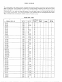
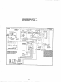
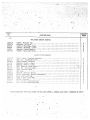
PARTS
This
catalog
applies
groups of related
to the standard
items.
CW Plants
Each illustrated
(including
part is identified
CATALOG
mobile application
by a reference
plants)
as listed
number corresponding
below.
Parts
are arranged
to the same reference
in
number
below the illustration.
Parts illustrations
are typical.
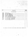
Using the Model arrd Spec. No. from the plant nameplate, select the
Parts Key No. (1, 2, etc., in the last column) that applies to your plant Model and Spec. No. This Parts Key No. represents
parts
that differ between
models.
Right and left plant sides
Unless otherwise mentioned in the description,
parts
are determined by facing the engine end (front) of the plant.
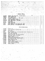
PLANT
DATA
&SPEC.
ELECTRIC
NO.
WATTS
VOLTS**
CYCLE
5CW- lM/
5CW-2M/
5CW-3M/
5CW-4MJ
5CW-5M/
5,000
5,000
5,000
5,000
5,000
I 20
240
120/240
120/208
60
60
5CW- 1R/
5CW-8 R/
5,000
5,000
5,000
5,000
5,000
5,000
5,000
5,000
5CW-53M/
5CV&54M/
5cw-57M/
5,000
5,000
5,000
5CW-53 R/
5CW-54R/
5CW-55R/
5CW-57R/
5,000
5,000
5,000
5,000
240
220/380
6,250
120/240
6,250
6,250
6,250
6,250
120/208
240
120/240
5CW-2R/
5CW-3 R/
5CW-4R/
5CW-5R/
5CW-6R/
5cw-7R/
6CW-53 R/
6CW-54FV
6cw-55R/
6CW-55DR/
6CW-56 R/
6CW-57R/
6,250
705 CW- I R/
705 CVi-2R/
705CW-3 R/
705CW-3R17/
705cw-4R/
705 CW-5R/
705 CW-5DR/
705cw-6R/
705 CW-7R/
7,500
7,500
7,500
7,500
7,500
7,500
7,500
7,500
7.500
8cw-3R/
8CW-4R/
8,000
8,000
8CW-53M/
8CW-54M/
8CW-55M/
8CW-56M/
8CW-57M/
8,000
8,000
8CW-53 R/
8CW-54R/
8cw-55R/
8CW-55DR/
8cw-56R/
8CW-57 R/
9CW-3 R/
9CW-4R/
10CW-5M/
I ocw-6M/
I 20
120/240
120/208
220/380
120/240
120/208
480
220/380
I 20
240
I 20/240
120/240
120/208
I
I
I
3
KEY
NO.
i
3
3
2
2
3’
4
3
2
2
2
2
2
3
3
3
3
4
4
2
2
2
50
50
50
I
3
3
3
4
4
I
I
I
50
50
50
50
I
3
3
4
3
3
3
4
2
2
2
2
50
50
50
50
50
50
I
3
3
3
3
3
3
4
3
4
3
4
60
60
60
60
60
480
220/380
[ 27/220
PARTS
WIRES
3
60
60
60
240
120/240
120/208
240
DATA
PHASE
I
I
I
I
I
60
60
60
240
L
60
60
60
60
60
60
60
60
3
I
I
I
I
I
I
2
2
3
4
——
4
4
4
4
4
4
2
2
3
3
4
3
4
3
4
4
4
4
4
4
4
4
4
4
60
120/208
50
50
3
3
4
4
4
120/240
120/208
240
480
220/380
50
50
50
50
50
I
3
3
3
3
3
4
3
3
4
3
3
3
3
3
[ 20/240
120/208
240
120/240
480
220/380
50
50
50
50
50
50
I
3
3
3
3
3
3
4
3
4
3
4
4
4
4
4
4
4
9,000
9,000
I 20/240
60
I
3
4
120/208
60
3
4
4
[0,000
120/240
120/208
240
60
60
60
60
I
3
3
4
3
3
3
3
3
240
120/240
480
220/380
I 120 / 240
J--8,000
8,000
8,000
8,000
8,000
8,000
,
models.
3
3
3
3
3
8,000
8,000
8.000
10CW-3M/
10CW-4M/
between
TABLE
*
MODEL
are interchangeable
10,000
I 0,000
I 0,000
480
.—
—
I
3
3
3
.-
—
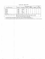
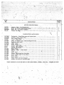
PLANT
DATA
*
I
MODEL
& SPEC.
NO.
WATTS
i
APPLICATION
PLAh
s ***
/
* - The Specification
Letter A
** - Reference
to 120, 240, 120
- Parts
PHASE
WIRES
lj%J
~
I 0:000
I 0,000
10,000
~
;%%
240
120/240
480
220/380
127/220
that Differ
Between
I
..
antes
3
4
3
(A
to B,
40 and 480-volt
bile
3
3
3
3
3
3
60
60
60
60
60
60
10,000
250
DC
1
~PECIFICATION
NUMBERS,
96, 665, 980,
i329,
1615, 1689, 1725, 1775, 1776, 1813, 1819, 1824,
1970, 1991, 2148, 2203, 2206, 22[7, 2428, 2537
!
Application
.—
B
to C, etc. ) with
Also
Applies
Planta
will
Manufacturtig
to 115, 230,
Also
have
KEY
NO.
I
60
I
L
***
PARTS
DATA
CYCLE
{
!
10,000
MOBILE
(Cont.)
EL ECTRI(
VOLTS**
,
I ocw-3R/
10CW-4R/
\
TABLE
1338, 1511,
1837, 1841,
4
3
4
4
4
4
4
4
4
4
4
2
5
1597,
1850,
6
Changes.
115/230
and 460-volt.
the Specification
Number
Shown
in the Part
Description.
—.
26
a’
,—...
23
()4-
?
.. .
—
22
‘w
,=.. ~
......
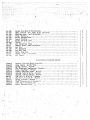
1
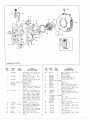
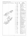
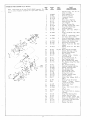
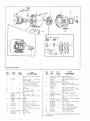
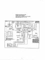
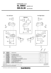
CRANKCASE
REF.
NO.
—.
I
PART
GROUP
NO.
QTY.
USED
10 IA236
I
2
IO IB373
I
3
10 I A367
I
4
PLATE,
IO IC67
10 IC268
REAR
Crankcase.
Brg.
Plate
IO IK341
2
-.
.-
6
516A72
7
8
505-274
517-48
9
10
502-2
520A I I
As
2
Req.
4
I
2
8
Rr.
seal)
Bearing
Rr.,
Kit,
Incl.
Prec.
Prec.
Type
I
/
, Frt.
Ref.
- Frt.
Washer
Type,
Specify:
Std. or .002”,
.020”
or .030”
Under.,
Original
Repl.
Equip.
Alum.
Pin,
Lock
(2)
&
16
17
f
I
Begin
Spec. J
Flanged
Brg.
on
Earlier
Thrust
Flanged
18
~:
1
21
Bronze
Faced,
.010”,
Kit
IO IK220
Used
Models
Washer,
Crankshaft
II
12
13
14
15
Prec.
Crankshaft
Thrust
10A
QTY.
PART
NO.
PARTS
USED
DESCRIPTION
8
805-18
.
5A
Pins,
I04B432
Oil
To Spec. E
Begin Spec. E
Bearing
Kit,
Crankshaft
J , See
& Rr. - TO spec.
&
5B
NO.
——
Brgs.,
&
Bearing,
Rr. Cam.,
(Repl.
IO IA50)
CRANKSHAFT
BRG.
No.
5A
(Incl.
REF.
Repl.
IO IA217
Bearing,
Cam.,
Frt.
Type (Repl.
10 IA70)
I
I
2
5
PART
DESCRIPTIONS
I
1
22
1
~
I
\
23
I
24
~
/
520A43 I
520A434
520A432
520A433
STUD,
GEAR
520A9
520A
520A
I I
I 18
509P64
IO IKI16
I IOB640
I IOA647
526-63
HOUSING,
IO IE 188
IO IE222
8
2
2
2
29
Rear
Brg.
Stud,
Stud,
Stud,
Stud,
Cyl.
BaSe
Cyl.
Base
Oil Base, Spec.
Oil BaSe, Spec.
Spec. B
Flywhl.
Hsg.,
Oil, Crank
Spec.
Gasket
2
2
2
(Assorted
Thickness)
Cover,
Valve
Box
Gasket,
Valve
Box Cover
Washer,
CopperValve
Cover
Screw
FLYWHEEL
Spec. A Only
I
I
Key 1,2,3,4,6-
Rr.
Begin
123A445
I
2,6
123A458
I
Tube,
B
Cap,
Breather
Spec.
B
I
Valve,
I
Filter,
Spec.
Breather
Rear
Brg.
25
15
A
I
Kit,
shaf~
403A95
IO IA154
123A3
A
A
Seal,
Key 5
Bolt,
Eye - Lifting
Plate,
Cover,
Flywhl
Opening,
Spec. A
123-452
,,
,,
A
I
I
I
10 I B229
Plate
E
I
I
~;
Place,
Spec.
COVER
Spec.
6
I
Begin
Stud,
6
Brg.,
(4) Separate
Thrust
Washers
Plug,
Countersunk
Hd.
Plug,
Exp.,
Rr.
Camshaft
Brg.
Opening
(Rep!.
517-18)
Elbow,
Oil Fi[ter
Lines
Stud,
Rear
Brg.
Plate,
To
Spec. E
Bolt,
Begin
Plate
Spec.
Hsg.
- Begin
Tube
-
Spec.
Begin
Breather
Breather
B
Tube
B
- Begin
“
-
‘.. ,.,
db-CI
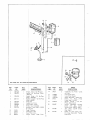
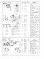
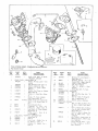
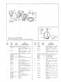
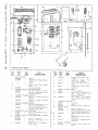
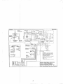
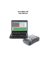
OIL
PUMP,
OIL
FILTER
& BY@
PART
QTY.
PART
NO.
——
NO.
USED
DESCRIPTIONS
I
2
120A222
120A22 I
3
120A224
I
Screlw,
(Repl.
Guide
120 A380)
4
526-153
I
5
6
i 20A279
I
Washer
(Repl.
Pump,
- Copper
526-69)
Oil
120K161
120 B275
I
Gas
I
I
Cup
122C56
122C122
10
193P6
II
12
13
122-37
502-57
505-52
,., - /’
ASS GROUP
REF.
7
8
9
20-+?
7
Pis~on,
Valve
Spri~g,
Oil
120~270)
et Kit,
REF.
PART
QTY.
NO.
NO.
USED
502-3
2
Connector,
to Filter
Line,
Filter
14
- oil
By-pass
By-Pass
(Repl.
PARTS
15
122B94
I
Oil
By-Pass
16
122B95
- Oil
By-Pass
17
18
120A 182
502-2
I
I
2
19
309BI0
Pump
Intake
- Pump
1
Filter,
Incl.
Cartridge
Bra~ket,
Fi Iter (Repl.
20
DESCRIPTION
Switch,
122C89
21
502-58
I
I
22
502-20
2
I
I
Car~ridge,
Filter
Tee! Filter
Inlet
El b~w,
Press.
Tee,
Mtg.,
Gage
Corm.
30
Flare
- Lines
Inlet
Line,
Filter
Outlet
Screw,
Shoulder
- Pump Mtg.
Elbow,
Flare,
Inv.
Filter
Lines,
Key 1,2,3,4,5
Switch,
Cut-off
Low
Oil
Press.
(Opt. ) Key 6
(Used
Switch)
& 122C 120)
Gag~, Pressure
Inv.
Momentary
Contact
with
opt.
cut-off
Repl.
308 P37, Key 6
(Opt. )
Key
Cut-off
Switch
6
Elbow,
St. (Two
Used
Oil
Gage
Optionally
Left) Key 6
to Mt.
Facing
.,
)
.
il
5+
---
1’
-—-,
If
1-
14
13
1:
+19+
11’”-
II--2’+
_
-23
.2&-
, —.
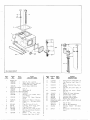
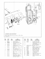
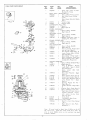
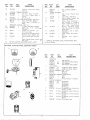
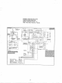
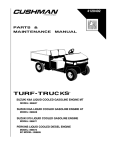
OIL
3EF.
NO.
———
I
BASE
GROUP
PART
NO.
QTY.
USED
BASE,
OIL
I02E220
I02E262
I
I
I 02E465
2
3
4
5
PART
i
FOOT,
/020223
OIL
I02B27
I
COVER,
I02A221
102A248
BASE
2
2
OIL
102A222
BASE
I
I
I
I02B215
REF.
NO.
DESCRIPTIONS
—
Spec. A, Key 1,2,3,4,5
Begin
Spec.
B, Key
1,2,3,4,5
& 6 (Except
Spec. 2428)
Key 6 (Spec.
2428 Only)
Spec.
A
Begin
Spec.
B
Gasket,
Oil
Elbow,
St.
Base
to
Crkcase.
7
505-268
Pipe,
8
505-29
Coupling,
9
10
II
505-130
123C402
12
23A380
Plug,
Oil Drain - 3/4”
Tube,
Oil Fill
- Spec. A Only
Housing,
Crankcase
BreatherSpec. A Only
Gasket
Oil
Fill
Tube,
I
-
Oil
Base
I
23C388
‘
2
Breather
Drain
Drain
Hsg.,
(3/4
123A437
I
Tube,
123 B409
I
Cap,
16
123A410
I
Gasket,
A Only
17
123A378
I
18
123A439
I
Indicator,
Only
Indicator,
Spec. B
Spec.
Oil
- Begin
Fill
Breather
I
Gasket,
19
402A36
4
Cushion,
20
21
22
23
402A38
402A46
526A 124
4
4
8
Cushion,
Bushing,
Washer.
Drain
x 9)
Pipe,
PART$
DESCRIPTION
15
(3/’4”)
Oil
QTY.
USED
13
18A
Optional
- For Heater
Assy,
Less Heater
Gasket,
Oil
Base
Opening
Cover
505-5
~
Spec.
Hsg.,
Spec.
B
A
Only
OPENING
Standard
6
PARTS
3/4”
24
123A191
MOUNTING
HARDWARE
402A 103
ASSY.
IN CL.
A Only
31
Oil
Oil
Level
-
A
Begin
Indicator
- Upper
Mtg. - Lower
Cushion
Spacer
Mt~. Cushion
REF;
19,20,21,22
With
6“
Bolt
4
With
8“
Bolt
333B42
I
Element,
I
Spec.
- Spec,
Level
Mtg.
4
309-29
Hsg.,
Level
Oil
402A219
(opt.
25
Breather
PLUS
(Optional)
Heater
-
Oil
Base
Heater
Cont.
)
Thermostat
(opt.)
- Oil
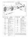
REF.
PART
PART
QTY.
I
NO.
NO.
-—
USED
—
~
DESCRIPTIONS
I
BLOCK,
I
VALVE
GUIDES
CYL.
- IN CL.
VALVE
SEAT
I I OC757
INSERT
- LESS VALVES,
Left Hand,
Std.
II OC1201
I
Left
Hand
with
& E haust
1
Optional
I IOC756
I IO C1200
3
4
I I 00644
INSERT,
I I 0A646
I
I
Righ4
Righ~
4
Intakk
lnserls
Guid~,
VALVE
2
I
& EXH.
Stellite
Valve
13
NO.
I IOD637
QTY.
PARTS
USED
DESCRIPTION
I
Inserts
Stellite
Valve
SEAT - STELLITE
- Specify:
Exha~st
Seat
Std.
,010”,
13
I IOD748
I
14
15
16
17
18
I IOB641
I I 0B645
I I OA707
I04A91
I IOA815
2
2
8
2
10
or
19
I IOA814
20
21
526A 127
I I 2-90
8
18
2
.025”
Over.
II OAI
5
191
2
Intake
- Optional
VALVE
I IOB642
II OBI 195
2
2
Exha~st
*Exhadst
Rotator
I IOB643
II OBI 193
2
2
7
I IOA738
4
Intake
*intake
Spring,
8
RETAINER,
I IOA648
VALVE
4
II OA1204
4
I I 0A620
4
8
- Stellite
- Std.
Stellite
- Optional
9
I IOA639
8
I I 5A34
4
II
12,13
520A I I
HEAD,
CYL.
Compression)
I IOD638
12
12
I IOD749
4
- (Be
.—
Comp.,
Right
Hand,
High Comp.,
Gas Fuel
Gasket,
Cyl. Hd.
Gasket,
Cy 1. Base
Nut, Cyl.
Base
Nut, Cyl.
Base
Screw,
Hex.
Mtg.
Screw,
For
Hex
Hd.
Washer,
Cyl.
Piston
& Pin
.010”,
.020”,
Over. (Repl.
Ring,
Lock -
Mtg.
Mtg.
Hd,
For
Cyl.
Cyl.
Hd.
Hd.
Mtg.
Hd. Mtg.
-Specify:
Std. or
.030”
or .040”
I 12-S5)
Piston
Pin
I12A19
4
I I 2A54
2
Pin,
24
113-105
2
Ring
Set - For
I Piston
Specify:
Std. or .010”,
.020”,
.030”,
.040”
Over.
(Repl.
25
2
Rod,
26
I 14B64
I 14B53
4
27
I 14B54
2
28
I I 4A20
4
Bearing
Half,
Con.
Rod Specify:
Std. or .002”,
.010”,
.020”,
.030”
Under.
Bushing,
Piston
Pin - SemiFinished
Washer,
Lock
Con.
Rod
Screw - (See Ref. 30)
29
I 14A57
4
Piston
- Specify:
Std.
or
I I 3-59)
- Std.
- Stellite
Valve
- Optional
I IOBI 195 Valves
- Optional
*Rotoc’ap,
Valve
- Used with
II OBI 193 & IIOBI
195 Valves
Connecting
Screw,
Corm.
Rod
-
(See
Ref.
I 14A20
&
30)
Valve
Sprg.
Retainer
30
Tappet,
Valve
- Incl.
Adj.
Screw
Stud, ~Exhaust Manifold
Sure Both Heads
are of the Same
I
Left
Hand,
Std.
Gasol ine Fuel
I
Left
Gas
Std.
Fuel
23
For
SPRlk G
Used with
I 10 B642&
I IOB643
Valve s
II OB1193
&
with
*Used
Lock)
Hand,
22
Optional
10
Right
Gasoline
Intake
Seat
& Exhaust
- Optional
Valve
.005”,
I
1
PART
ETC.
Hand, Std.
Hand,
with
.002”,,
REF.
NO.
.—
Hand,
#uel
High
Comp.,
Comp.
805-20
4
Bolt,
Place
- Repl.
I 14A57
* - The optional
Stellite
Valve
has its groove
located
1/4”
from end of stem to accommodate
optional
Rotocap
Valve
Rotatora
and not change
spring tension.
If the Rotoc ap is
For
not used on this valve, the optional
(13/64”
thick at O. D.) is required
For
32
110A 1204 Spring
for proper spring
Retainer
tension.
.
—.
-—.. —
II
54
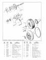
: RAN KSHAFT,
CAMSHAFT,
FLYWHEEL&
BLOWER
WHEEL
L
REF.
NO.
—.
I
2
3
4
PART
NO.
QTY.
9EJL
I
I
2
I
I04D 172
I04BI
515-1
I04A365
5
51&16
6
I05AI
I
I
PART
DESCRIPTIONS
Crankshaft
Gear, Crankshaft
Key, Crnkshft
& Camshft.
Gr.
Washer
& Slinger,
Crnkshft.
Gear (Repl.
I04A95)
Ring,
Lock
-
Crnkshft.
l–
Gr.
Washer
.
.
12
I
105 B107
150A4 13
150C417
I
I
I
12
Camshaft
7
8
9
10
510-46
II
150A440
I
12
I 50P437
I
Ring,
13
I05A42
I
Washer,
14
516AI16
15
CRANK,
192C259
2
-
Incl.
Gear, Camshaft
Plate,
Back -Gov.
Spacer,
Gov. Ball
Ball,
Fly - Governor
Cup,
Pin,
Center
Pin
Ball
Spec.
(Repl.
PART
NO.
NO.
—
QTY.
Snap
Roll
DESCRIPTION
16
17
192C268
150A435
I
I
Pin,
18
FLYWHEEL
104D 192
I
Key
1,2,3,4,6
104A205
I
Key
5-
19
I04A160
I
Washer,
20
5 I 5-90
I
Key,
21
22
23
134C388
134C387
192B193
I
I
I
Wheel,
Hub, Blower
Wheel
Support
Guide,
Crank
2
Dowel
Pins
Pin,
Dowel
24
516AII
Begin
Spec.
- Center
Thrust
PARTS
USED
—
Governor
Pin
- Cam.
- Crank
Guide
25
A,
B - Housed
192 C204)
520A45
I
I
Gear
Pilot
HAND
I
REF.
Plants
Spec.
Center
Incl.
Ring
Gr.
Flywheel
Flywheel
Mtg.
Blower
- Spec.
- Crank
- Incl.
A,B
Support
-
A,B
Stud,
Blower
Spec.
A,B
Crank,
Wheel
26
I04B252
I
Dog,
27
104- I 37
800-75
I
I
Gear, Ring - Key
Screw,
Dog Mtg.,
28
C (Repl.
33
C
Camshaft
806-38)
Begin
& Support
Spec.
5
Begin
C
Spec.
,.-.
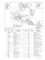
GOVERNOR&
Note:
GEAR
Vacuum
COVER
booster
parts
GROUP
do
(705 CW-3R17/).
not
apply
to
X-Ray
models
I
I
REF.
PART
QTY.
~
NO.
—.—
NO.
USED
—
I
2’
3’
4.
150AI15
150A96
150A398
150A639
I
I
I
5.
6
150A410
150A495
I
1-
7
150A47
I
PART
I
DESCRIPTIONS
Spr(ng,
Governor
Stud, Gov. Sprg.
I
3,4,5,6
Rind,
150A425
I
9
150K580
I
10
150K582
I
Gasket
-
Man!
- Key
3,4,5,6
Kit,
,Eooster
Repl.
Kit,
lBooster
Diaph,,
19
- Key
Booster
Key
to
3,4,5,6
Key
3,4,
II
150A475
I
SPring,
4,5,6
12
150,4376
I
13
150A666
I
14
150A668
Brat’ket,
Booster
Int.
Sprg.,
Key 3,4,5,6
Plate,
Diaph.,
Booster,
Key
3,4,5,6
(Repl.
150 A373)
Gasket,
Diaph.
Plate,
Key 3,
4,5,4
(Repl.
- Int.,
I
I
I
516-39
516-85
Key
I
COVER,
I03CI15
GEAR
25
26
27
28
29
30
31
3,
DESCRIPTION
—
Pin, Cotter,
Key 3,4,5,6
pin,
Roll,
Key 3,4,5,6
Housing,
Vacuum
Booster
Sold Separately)
Cover,
Vacuum
Booster
(Not Sold Separately)
34
Hsg.
- ASSY.,
IN CL. REF. 20-29
Spec. A
Begin Spec. B (Repl.
I03C140)
I
I
I
Seal,
510-14
I
I
Bearing,
Needle
Ball,
Brg., Shaft
(Lower)
Thrust
509-46
Shaft
509- I 9
510-48
5 I o-49
Oil
Bearing,
- Crnkshft.
Needle
Frt.
(Upper)
I
Seal,
150A444
I
Yoke,
516-90
150B416
150A438
I
I
I
Pin, Stop - Gov. Cup
Arm & Shaft Gov.
Screw,
Adj. - Gov. Sensitivity
150A4
I
Bracket,
I
I
Gasket,
Gr. Cover Mtg.
Stud,
Arm Cover
Mtg. - Spec.
I03CII0
520A363
I I
Oil
A Only
150 A374)
(Not
I
I03C173
20
21
22
23
24
5,6
BOoster
USED
18
Sprg.
PART
QTY.
PART
NO.
——
(Repl.
Lin~,
Gov. Arm to Carb.
Bra~ket,
Booster
Ext.
Key13,4,5,6
Spri~g,
Ext.
Booster
8
NO.
Is
16
17
Tension
Nut~ GOV. Spd. Adj.
Joir+
Ball,
Gov.
Link
I 50 A300)
REF.
- Gov.
Governor
Gov.
Shaft
Spring
REF.
B@=’”
‘L
y;”
l!Z
‘%’
1A
~~~~~5
,DE’;gP;;’oNBegin
--—..
;g
“IBF
~
EZ;;rz;i
Spec,
G
(Note:
Wrapper
not
,..
17
7 ‘-
‘“-
:-,
%%%f?
m
6
5 I 7-9
I
7
140B467”
I
8
140A357
I
8A
145A239
I
~
Plug, Button
-Spec.
F
Gasket,
Spec.
B
(Repl.
508-73)
Inlet,
3A
through
F
Inlet,
Carb. Air (Metal)
Spec.
B through
H - Order
145A239
Rub. Inlet,
145A246
Bushing,
503 P368
@
B through
Clamp
Carb.
Bushing,
(Air
Carb.
Horn)
Air
Rubber
Inlet
for
4
@
2:
22X
‘B
>-&
‘::
:
E::;’:::.%ii:;
I
Metal
Inlet to Carb. - Spec.
B
through
H
Clamp,
Hose
- Rubber
Inlet
Spec. J
to Car b., Begin
4
~
.\#l@$’
;
,{ir
~“
‘Yp%g
,0
,0
~.@
‘0’
7.
/’/
‘Y
CLAMP,
503-274
503-274
HOSE
Air
8
‘
I
‘&
lR CLEANER
:&
GROUP
10’
PART
10.
—
NO.
USED
QTY.
DESCRIPTIONS
I
140A343
[
2
140D355
1
2A
140D53
Cleaner,
Air - Oil Bath Type,
Spec. A (Repl.
140 C266)
Housing,
Mesh
Type
- Spec.
B through
F
Housing,
Cart.
Type
- Begin
I
I
Spec.
3
1406356
I
3A
1406532
I
4
520A75
2
133A32
10r2
12
503-259
I
13
14
503A215
133K30
I
[
15
503-269
3
Clamp,
I
heater
Hose,
(1)
Air
Hose to Air Clnr. )
Breather
Cap
Hose,
16
503A275
Tube,
A (l),
Air
Pre-heater
- Spec.
Begin Spec.
B (2)
Hose
(3-1/8”)
Also
System
17
~ \’23A41
508-3
I
I
GROUP
35
Group)
-
(2)
Air
PreClnr.
to
Air
Begin
Spec.
B
Optional
Fuel
Spec.
A
I
Tube,
Breather
Cap
to Air
Clnr.
(See Also
Optional
Fuel
System
Group)
Spec. A
I
Grommet,
Rubber
- Air
Clnr.
(For
I 1/32”
Hole)
Spec.
B
Through
;NITION
Inlet
Hose,
Air
Pre-heater
- Begin
Spec. B
Hose, Air Pre-heater
- Spec. A
Pre-Heater
Kit, Air - Spec. A
Air
Adapter,
Hose,
(Incl.
Clamps
& Tube)
Inlet
(See
,..—.
Carb.
II
G
Cover,
Mesh
Type
- Spec.
B
through
F
Cover,
Cart.
Type
- Begin
Spec. G
Stud,
Mesh
Type
- Spec.
B
through
F
to
503A368
+
PART
:F.
Hose
10A
9
o
Clnr.
F
MAGNETO
Note:
sure
PARTS
GROUP
parts
are for
These
to
replacement
check
magneto
(Typ~e
type
FM-PEI)
FM-PE
nameplate
for
I-2 B69A
type
magneto.
before
REF.
NO.
Be
ordering
PART
NO.
PART
QTY .
USED
DESCRIPTIONS
parts.
16 I C238
Magneto
Assy.,
(Repl.
Incl.
Dr.
Gr.,
161 A148)
I
2
160B339
161-242
I
I
Gear, Msg. Drive
Point
Set,
Incl.
Stationary
Brkt,
3
4
5
6
161 A178
161 P210
161 P212
I
I
Condenser,
Magneto
Cap, End
Rotor Assy.,
Magnetic
161 P217
I
Bearing,
Roller
Arm
-
&
Rotor
Cam
End
~
I
I
I
I
I
7
8
9
10
II
12
13
161 P211
161AII
161 PI18
161-19
161-236
161-120
16 I P224
4
I
Coil,
Magneto
Ferrule,
Grd. Term.
Insulator,
Grd. Term.
Ring,
Drive
Shaft Snap
Housing,
Magneto
Screw, End Cap ( IO-24x
5/8”)
Screw,
Condenser
Mtg. (8-32 x
14
16 I P223
I
Screw
1/4”)
30
Arm
KA’W
‘?/24
&
Lockwasher,
Brkr.
Term.
Is
161 P231
I
Screw & Lockwasher,
Support
Locking
(8-32
Contact
x 5/16)
16
17
161 P123
16 I P226
Outlet,
High
Tension
Set Screw,
Coil
Bridge
Cable
18
161-128
2
2
I
Washer,
Rotor
Dr.
End
Seal
Rotor
Dr.
End
Seal
Rotor
Dr.
End
Brg.
(Outer)
19
161 P213
I
Washer,
(Inner)
.
‘
-48
‘\.
20
161 P214
I
Washer,
Retaining
21
22
23
24
161 P215
161-136
161-170
16 I -243
I
I
I
I
Gasket,
End Cap to Hsg.
Spring,
Contact
Support
Hub, Coupling
Coupling
Assy.,
Impulse
Incl.
23, 25, 26
Spring,
Impulse
Cplg.
25
161-51
I
26
27
161-131
161-96
I
I
28
161-172
I
29
161-53
161-135
16 I -240
I
I
I
30
31
32
33
34
35
36
37
38
Shell,
Impulse
Spring,
-
,,.
Dr.
Cplg.
Impulse
Cplg.
Pawl
Pin, Impulse
Cplg.
Pawl
(3/8-16)
Nut, Impulse
Coupling
Bushing,
Impulse
Coupling
Washer,
Coupling
Plate
161 P164
I
Nut,
Ground
16 I P230
I
161-62
I
I
I
I
4
Wick
Seal,
& Holder,
Cam
Rotor Drive
End
161-186
161-I 19
161 P216
814-77
Grd.
Stop
Cable
Spring,
Terminal
Support,
Coil
Lead
Ground
Cable
Bearing
Screw,
Brg.
Support
(8-32
x
3/8”)
39
40
161P71
526-3
I
I
Bearing,
Washer,
Rotor
Contact
Drive
Locking
Screw
Plate
41
42
43
161A79
161 P219
16 I P220
I
I
I
44
161 P221
45
515-1
I
I
Washer,
Ground
Terminal
Cover,
Vent
Screw,
Vent
Cover
(6-32
1/4”)
Screen,
Vent
Key,
Rotor
Shaft
End
Support
to
x
Impulse
Cplg.
I
Screw,
Washer
46
16 I -244
47
850-25
Rotor
Dr.
(8-32 x 3/8”)
Brg.
Lockwasher,
161 P232
I
Screw
Washer,
Brg.
Support
Grease
I
Retaining
Washer,
(Outer)
Brg. Support
Grease
48
49
161 P213
Retaining
36
(Inner)
End
Brg.
Retainer
___-= ... ------ . .. .. .. .. ——,—.
MAGNETO
—..
PARTS
..
.
.
GROUP
..—.
FM-JEI)
(Type
Note:
These
parts are
sure
to check
magneto
parts.
.
REF.
for type FM-JE I-2 B69A magneto.
Be
nameplate
for type
before
ordering
NCI.
..
PART
No.
I
2
3
4
PART
CITY.
USED
160B339
161-86
161 A178
DESCRIPTIONS
I
I
I
I
Magneto
Assy.,
Incl.
(Order
16 IC238)
Gear, Magneto
Drive
Point
Set, Contact
Condenser
Magneto
Cap, End
Dr.
I
I
Rotur Assy.,
Magnetic
Bearing,
Rotor Cam End
Gr.
5
161 P210
161-169
6
161-72
7
8
9
10
II
161-168
161AII
161 PI18
161-19
161-236
12
161-120
I
I
I
I
4
13
16 I P225
I
14
16 I P225
I
Screw
Arm Term. (8-32 x 3/8”)
Screw & Lockwasher,
Contae-t
Support
Locking
(8-32 x 318”)
Coil,
Magneto
Ferrule,
Primary
Grd.
Insulator,
Primary
Grd. “Term.
Ring,
Rotor Shaft Snap
Housing,
Magneto
Screw,
End
Cap
( IO-24
x
5/8”)
Screw,
Condenser
Mtg.
(8-32
X 318”)
\:.
\
q,, ,y~i’
42
~
35
7
Brkr.
16 I P225
2
16
161 P123
161-239
161-128
2
17
18
2
I
Outlet,
High Tension
Cable
Set Screw,
Coil
Bridge
Washer,
Rotor
Dr:
End Seal
19
161 P213
[
(Outer)
Washer,
Rotor
Dr.
End
Seal
(Inner)
-!3–
4+
,.;,
43”,/’
.,’
‘d “ ,
Lockwasher,
15
II
~.@
&
,,, “
,,
____
/
/
3Y
I&i
\.,_,,/’
:>b{”;o
2/
/
.,,
\
8 16 ‘“-z+
/
/
/ ‘
77~
14
.(
/’
.
-.,
/
20
21
22
23
24
161-56
161A42
161-136
25
26
27
28
161-S1
161-175
161-96
161-172
I
29
161-53
161.135
16 I -240
I
I
I
161 P164
161-112
161-62
161-186
161-119
161-173
814-77
I
I
2
I
I
4
161-170
161-171
As
Req.
I
I
I
I
. ‘%~;&
‘(
49
30
31
32
33
34
35
36
37
38
50
-
Nut, Impulse
Coupling
Bushing,
Impulse
Coupling
Washer,
Coupling
Plate
39
161P71
40
526-3
I
2
Nut, Ground
Cable
Wick & Holder,
Cam
Seal, Rotor
Drive
End
Spring,
Coil
Lead
Terminal,
Ground
Cable
Support,
Bearing
Screw,
Brg.
Support
(8-32
x
3/8”)
Bearing,
Rotor
Drive
End
Contact
Washer,
Support
41
42
43
161A79
16i A2i9
I
I
Locking
Screw
Plate
Washer,
Grd. Term.
Cover,
Vent
16 I P220
I
44
45
161 P221
515-1
46
161-18
I
47
48
49
161-241
161-35
812-61
161-116
161-113
161-114
I
I
50
51
52
37
Shim, Rotor Dr. End Brg.
Gasket,
End Cap
to Hsg.
Spring,
Ground
Switch
Hub, Coupling
Coupling
Assy.,
Impulse
Incl. 23, 25, 26
Spring,
Impulse
Cplg.
Dr.
Shell,
Impulse
Cplg.
Spring,
Impulse
Cplg.
Pawl
Pin, Impulse
Cplg.
Pawl
Stop
(3/8-16)
I
Screw,
1/4”)
Vent
Screen,
Vent
Cover
(6-32
Key,
Rotor
Shaft
to Impulse
Coupling
Ring,
Rotor
Bearing
Snap
Washerj
End Cap Plate
Screw,
Screw,
Contact
Cam Wick
Lockwasher,
Cam
Spacer,
Cam Wick
Washer,
Cam Wick
Support
(6-32x
Wick
Adj.
3/8”)
Screw
x
24-+?s=’-”o
A.J-’
I)
FUEL.
Fuel
REF.
No.
SYSTEM
System
GROUP,
DAR13
Group)
.—
PART
-—
STAN
1
149D6Y3
PLIMP,
Optional
I
PART
DESCRIPTIONS
Pump,
149q405
2
Also
I
QTY.
USED
_
NO.
(See
1
Fuel
Spec.
& 149 C559)
- BEGIN
SPEC.
B
—
With+ut
Priming
FUEL
I 49C567
REF.
NO.
—.
A
Lever
(Repl,
3
4
154A252
149C528
I
2
I
5
149A277
I
Gas~et,
6
149A388
I
Spacer,
Ai
7
149A520
I
Spat er, F1.
Mtg. - Begin
8
502-2
with ~priming
Lever
- Key 1,3
Gasket,
Intake
Man. Mtg.
Adapter,
F1. Pump - Begin
Speci
B
Begi[]
As
Req,
Fuel
Spec.
F1.
~,
Pump
to
Adapter
Mtg.
Pump
Spec.
Fuel
Line
Connection
A (3),
Begin
Spec.
;;::
159A477
I
Bracket,
F1. Line
Begin Spec. B
18
508-2
I
Grommet,
Rubber
- FI.
Line
Support
Brkt. - Begin
Spec. B
Line,
FI Tank to plant.
Cap, Rain --Rubber
50 I A27
415A124
415 B126
22
23
504A
24
B
9
868-3
10
502-3
Nut, ,Carburetor
Connkctor,
Fl,
II
149A519
I
Pum~
Out.
- Begin
Spec.
B
Rod, lPush -F1.
Pump Adapter
12
149B79
I
Stud
Line
.
I
I
25
13
I
154A133
I
INTAKE
I
F1.
154D3
14
Key 4Gasket,
13
14
15
I-l NE, FUEL
149A533
149 B403
159B407
Spec.
B
154A266
to
I
Key
Also
I
Line,
I
FUel
Pump
Bracket,
Spec.
- Supply
in.
Ft.
A
154D3
- Spec.
Supply
Con.
to
A
Con,
-
26
800-52
15
I
Key
I
2
Spec. L
to Manifold
1,2- Begin Spec. B (Note:
for Key 4, X-RAY
only
Spec.
3,4
Key
4,
154D253)
- PUMP TO WRBURETOR
I
Begin
Spec. B
I
Spec/ A
F1.
14YA171
-
Begin
Carb.
Key !,2. - Spec. A (Note:
Also
for Key 4, X-RAY
Only -Spec .
A)
Begin
~~~~,sp;~~~
Seriai
508834
-
Tank,
F1. (5-Gal. ) - Repl.
415AI0
I
Valve,
Shut Off - F1. Tank
- GASOLINE
Key 1,2
I
Key 3,5 (Also
Key 4,6 - To
Spec. F)
I
Key 4,6 - Spec. F through
K
CARBURETOR
141 C560
14 I C564
MANIFOLD,
154D253
Support
I
141 C621
i4 I C655
(2)
2
I
19
20
21
- Spec.
Adapter
B
PART
DESCRIPTIONS
17
B
Pump
QTY.
USED
- Key
2,4,5,6
149C530
PART
NO.
B)
- Spec.
A (Note:
X-Ray
Only
-
For
Use
Key 3,4,5,6
- Begin
Spec.
B
(Note:
For Key 4, X-RAY
Only
Use i54D314)
Screw,
Hex Hd.
to
Repl.
Man.
(3/8-16
520A3 I 1)
Mach.
X
- Carb.
1-1/2)
-
.. . .... .,.
FUEL
.-—.-.
PUMP
PARTS
GROUP
PART
NO.
NO.
I
149D693
2
PUMP,
FUEL
I 49C530
r
PART
QTY.
REF.
USED
DESCRIPTIONS
I
Pump,
Blaking
Fuel
Mfr.
- Spec.
Pump)
A (Repl.
- BEGIN
SPEC.
B
I
Key 1,3 (With
Priming
Lever)
I
Key 2,4,5,6
(Less
Priming
149C567
Lever)
3
Body,
Upper
(Note
Sold
Separ-
ately)
4
5
6
DIAPHRAGM
149A582
149P276
7
SPRING,
149A672
.:,
0
@
,“ -
2
2
149A96
149A95
& PULL
ROD
I
** Spec. A
I
LBegin
Spec.
DIAPHRAGM
** Spec.
I
I
149P576
17
8
RETAINER,
149A539
149 P575
149A 159
9
10
*Valve
& Cage
*Gasket,
Valve
SPRING,
149A675
B
A (Repl.
Begin
Spec.
149A93)
B
VALVE
I
Spec. A (Repl.
149A84)
I
Begin
Spec. B
**Gasket,
Valve
Ret. - SPec.
2
(Blaking
Mfr. Pump Only)
ROCKER
I
ARM
** Spec.
149 P580
I
Begin
Spec.
II
PIN,
ARM
I
I
I
Spec.
Begin
A (Repl.
516A25)
Spec. B
12
516Ai13
149 P578
I 49-7 I o
13
]4
ROCKER
149P58
I
I
149A55
I
I
15
509-65
16
[ 49.A404
17
GASKET,
149A3
Lever,
Primer
MOUNTING
**spe=.
2
I
I
A (Pump
LBegin
Ring,
Shaft
Mfr.
I
20
20
I 49A4~
21
22
23
I
I
4
2
815-148
815-147
24
149 P579
I
25
149P577
I
Pump
149P483
I
27
2a
149A275
149 P793
I
I
Mtg. )
Priming
A
(Onan
Only)
(Not
Sold
Bail,
BOW I Retainer
-
Spec.
Bowl,
Screw,
Screw,
B
StrainerBegin
Pump Assy.,
Valve
Retainer,
Spec. B
Spec. A
Spec. A
Begin
Rocker
Arm
Link,
Spec. B
Bushing,
Rocker
Arm
Begin
26
-
- Spec.
Lower
Body,
Separately)
I
149 P573
A(Onan
& Spacer
Spec. B
E Retainer
Lever
19
- Spec.
Mfr. Pump Only)
Seal,
O-ring
- Primer
Lever
Spec. A(Onan
Mfr. Pump Only)
Sprin~,
Primin~
Lever
- Spec.
A (O~an Mfr. Pump Only)
I
5[8-129
149A94)
B
Arm & Link
Set, Rocker
(Sold
only as a set ) Spec. A
Arm, Rocker
- Begin Spec.
B
2
149A277
18
A (Repl.
A
Spec.
Screen,
B
Begin
Pin
-
B
Strainer
- Begin
Spec.
LGasket,
Bowl - Begin Spec.
LSeal,
Diaphragm
Pull
Rod
B
-
Begin
Spec.
B - Note:
Req. to
maintain
crankcase
vacuum
with
pumps
having
lower
body
29
815-135
30
850-30
REPAIR
149K526
6
6
PARTS
KIT,
I
149 KI06
—..
.
vent
I
prior
All
parts
Pump
only.
to
assembly
——
39
serial
listed
Carter
Begin
508834)
149 C567,
for
Begin
Mfr.
parts
Body
FUEL
PUMP
Spec. A $ Incl.
*&+$
Spec.
Marked
Note:
Mfr.
hole.
Screw,
Body
Lockwasher,
Parts
Marked
B - Incl.
Parts
L & *
Spec.
Pulmp
are
Screw
not
B Malls.
(used
during
available,
are
for
Spec.
use
AC
B
pump
REF.
PART
No.
-—
— NO.
I
2
CARBURETOR
141 C560
141 C564
I
I
141 C621
I
141 C655
I
CARBURETOR
14 i C492
141 C494
I
I
141 C622
I
141 C656
I
4
- GASOL INE
Key I ,2
Key 3,5(
Spe c. F)
Key
BODY.
AIR
I 41-530
I 4 I -666
141-531
INTAKE
I
I
I
4
SHAFT,
14 IA478
7
8
9
10
II
12
13
PLATE,
14 I-532
14 I-667
141-471
141-8
Spec.
4,6
To
F Through
Spec.
K
1..
Gas -GasolineGasrGasoline
Spek. F
GaslGasoline
F Through
K
Gas-Gasoline
Spec. L
Gasl(Only)
Gas~(Only),
-
Key 2
Key
4
-Key
4,6
- Key
-
To
- Spec.
4 - ~egin
- IN+
CHOKE
To Spec, L
Begin Spec. L
B~s~ing,
Choke
BUSI+.
Shaft
Key ~4,6 - Begin
-
I
I
To Spec. L
Begi,n Spec. L
Screw,
Choke
Plate
I
141-533
141-566
141-534
I
I
15
16
17
18
141-72
141-536
141-537
141-538
1
1
6
I
Key
Spec.
4,6
-
Axle,
I
Pluglj Fuel Filter
Head
Fi[tqr,
Fuel Inlet
Was~er,
Gasket
- Filter
FLOAT
141-535
I
Gas~l
14 IA493
I
Gas-’Gasoline
ine Carburetor
40
4,6
-
19
23
4
I
Plug,
I 41-540
141-541
I
Jet,
141-542
I
23
141-543
I
Plug,
ator
Plug,
1
Channel
Gasket,
-Bow
Lead
Bushing,
Idle
Blank
Jet
I Passages
Channel
- Accelerator
Channel
- Acceler-
Accelerator
Gas
Pump
Adapter
Rod
- Gas
Carb,
or
Only
25
148 B197
i
Adapter,
Gas
Fuel
Gas-Gasoline
Carb.
26
148A135
I
27
28
29
141-70
141-544
I
I
Lock,
Float
- Gas-Gasoline
Carb.
Only
(Not
needed
replace
with
pipe plug. )
Plug,
Bowl Drain
Plug,
Power Jet Channel
14 I-545
I
30
31
141-546
14 I-585
2
I
32
14 I K586
I
33
34
:3.5
36
37
38
Plug
- Key
Intake
to Bowl
Intake
to Bowl
Fuel
p.lncl.
Ref.
141”539
148A 198
Shaft
F
Float
Gasket,
Screw,
Bowl,
through
19
F
Idle Adjusting
Idle Needle
Carb.
Arm,
Choke
Begin
Sp.ec.
20
21
22
To
CHOKE
141-9
I
L
I
Needle,
Spring,
153A214
Gas-Gasoline
SHAFT
Key
1,2,3, S (Also
“To Spec. F)
PART
DESCRIPTIONS
QTY.
USED
14
24
- Key 2
Key 4,6
I
2
I
PA R-T
NO.
.—
FUEL
CHOKE
141-624
6
Key
- Begin
NAL
Sped.
rJ
Also
4,6-
Key
I
I
REF.
No.
DESCRIPTIONS
- OPTIO
141 C562
141 C519
3
PART
QTY.
USED
—
I
I
815-133
141-551
14 I-257
I 4 I-552.
141-2
2
I
I
VENTURI
141-484
I
——. .—.
Bowl
Gasket,
Body
Screw,
Bowl
to
Body,
Plate
Throttle
& Brgs. )
Shaft
&
Lever
- Gas
Only
to
Throttle
Body
(Incl.
Kit,
1,2-
Gasoline
Shaft,
Throttle
Incl.
Stop Screw
Screw,
Lever
Stop
Plate,
Throttle
Screw,
Throttle
Plate
Lever,
Clamp - Throttle
Screw,
Throttle
Lever
Key
or
-
-
Clamp
Carb.
—— .
.-—.—...—.
REF.
PART
QTY.
NO.
NO.
USED
I 4 I P573
148A 195
I
I
Key 3,4,5,6
- Gasoline
Carb.
Key 2 - Gas or Gas-Gasoline
Carb.
148A 196
I
Key
39
I 41-553
I
Jet
40
141A77
2
41
141-554
141-555
I
Washer,
Main
Fuel Valve
Jet, Idle
I
I
Jet,
Jet,
I
Valve,
...
~....
PART
DESCRIPTIONS
141-556
,,
7:,
\bt
141-323
44
QTY.
NO.
USED
PARTS
DESCFtl
PTION
141 A501
I
Spring,
Gasoline
46
148A17
I
Gasket,
Float
Gas-Gasoline
47
504-7
I
141 P590
I
Discharge
Well Vent
Valve,
Gasoline
In. Shutoff
Key
2,4,6
Gas-Gasoline
Carb.
Kit,
Repair
- Throttle
Body
Needle
Bearing
- Incl.
Seal &
Washer
141-563
I
Kit,
Repair
- Carb.
Fuel
14 I -529
I
Kit,
Gasket
- Carb.
4,6-Gas
or Gas-Gasoline
& Adj,
Needle
Assy.,
Adj.
Main
Needle
&
Inlet
“r.
I
PART
NO.
45
Carb.
42
43
REF.
,,
Choke
Carb.
Stop
Lock
Carb.
-
Bushing
-
8A
.. .
,,. ..
Gas-
p.,
,’
16
5
4
6
—.
14%
9
-. ..
v
13{
,. . .......
15.4
10
“.6;
- -.,
c“‘F
&.
CHOKE
REF.
No.
I
2
3
.—..
GROUP
PART
—
NO.
QTY .
USED
—
I
153A155
14 IA502
I
141 A372
I
4
153A58
I
5
I 53-57
I
6
COVER,
CHOKE
153A 162
I
153A50
7
8
8A
LEVER,
145A60
145-172
BRACKET,
14 IA496
153A347
518 P176
I
REF.
PART
DESCRIPTIONS
NO.
Adapter,
Choke -For
Gasoline
(Only)
Carb.
- Key 2,5 (Also
Key 4,6To Spec. F
Adapter,
Choke
- For
Opt,
Gas-Gasoline
Carb,
- Key 2,
4,5, - To Spec. L (Note:
Used
only
as choke
lock for Key 4
Spec. F through
K)
Knob,
Choke
Shaft - Key 2,5
(Also
Key
4 - To Spec.
F)
*Housing,
Choke
Bimetal
- Key
2,5 (Also
Key 4,6- To Spec. F)
*Element,
Bimetal
- Key
(Also
Key 4,6 - To Spec.
9
12
153A252
DESCRIPTION
CONTROL
I
Key
I
Key
AUTOMATIC
I
I
I
- SISSON - KEY 4,6
Spec. F through
K
Begin
Spec. L
Cover,
Choke
Incl.
Htg.
Key
4,6,
Begin
Element,
I
[3
2,5
F)
LINKAGE,
153A2S3
153A344
153A254
153A343
CLIP,
Clip,
Choke
Rod to
1,3 Begin Spec. L
Brkt.
- Key
14
15
16
END
SPEC.
F
518-5
518-47
153A214
153A256)
(Repl.
Auto.
Begin
Choke
Spec.
-
- CHOKE
I
I
I
5pec.
LINKAGE
Key
F
AUTOMATIC
CHOKE
- KEY 4,6
Gasoline
(Only)
Carb.
I
Spec. L
Gasoline
(Only)
Carb. I
Spec. L
I
Optional
Gas-Gasoline
To Spec. L
I
Optional
Gas-Gasoline
Begin
1,3,6
F
Bracket,
4,6-
I
I
- KEY
1,3
6
Spec.
CHOKE
I
ROD, CHOKE
14 I A497
II
10
PARTS
USED
153A18
CHOKE,
153 P213
153A337
153A346
- INCLUDES
HEATING
ELEMENT
*28-Volt
- Key 2 (Also
Key 4,6
To Spec. F)
6-Volt
- Key 5
SHAFT
Key 1,3
Key 6
CHOKE
CONTROL
ROD
To Spec. L
Begin Spec. L
I
QTY.
PARTS
NO.
——
To
Begin
Carb.
Carb.
L
- KEY
Carburetor
End
Choke
End
Arm,
Choke
Shaft
Begin
Spec. F
4,6-
-
BEGIN
Key
6 -
‘-’
-4
OPTIONAL
FUEL
(Combination
SYSTEM
GROUP
Gas-Gasoline
o) Gas
Only,
Downdraft
Carburetor)
I
I
I
1’
REF.
No.
——
I
1A
PART
,
No.
PART
QTY.
DESCRIPTIONS
—
USED
~
REGULATOR,
Manufacturer.
148C3 I I
GAS
(~heck
Reg.
Nameplate
for
Order
Pa~ts Accordingly)
I
Ga~retson
ManufactureUsed
, Begin
Serial
57357 I
- Key
2, ,6
Ensi gn
Manufacture
- Used
1
serial
57357 I - Repl.
Prior
148A-428
148A9
2
LINE,
GASOLINE
LINE
MDLS.
149B43 I
149A533
3
l-U BE,
503A267
- Key
- PU MP TO
- KEY
I
I
BREATHER
MODELS
123A412
2,4, 6
Sp ec.
Begin
A
Spec.
(Ru~bber)
503A266
Key
I
1
Ke)
Ke~
I
503A3
4
148A2
18
14
I
I
6
CARBURETOR
14 lC492L”
I 4 I C494
14 I C622
141 C656
- GAS-GASO-
159 B294
I
I
Hose,
Tank,
Feed
9
505-135
I
10
505-13
Nipple,
Key 2,4
Bushing,
B
GAS-GASOLINE
I
I
I
I
CARBURETOR
Reg.
& GAS
13
Key
15
505-101
17
307P3
Ch~okep
la
14 I C562
I
(O~lY)
Ke~ 2
141 C519
I
Key
4,6
Gas
Ensign
with
Ke~ 4,6 - Spec.
B Through
E
(Use
with
Garretson
Reg.
On~ly)
Key 4,6 - Begin
Spec.
F (Use
with Garrets on Reg. Only)
Fuel
- GAS-G~ASOLINE
Key 2
Ke~ 4- To Spec.
- GAS
B (Use
505-57
Ensign
Half
- Gas
Reg.
Out.
Reg.
Out.,
Use
Reg.
Only)
-
Key
CLAMP,
GAS
HOSE
(Note:
The
0.D.
of the Gas
Fuel Hose varies,
select
appropriate
clamps. )
2
3/4”
O.D. Hose
503-27
7/8”
O.D. Hose
2
503-32
15/16°
O.D. Hose
2
503-49
I
Vent (Use with
Garretson
Reg.
148A 107
On Iy)
I
Elbow,
Pipe
- 3/8”
(Used
505-39
14
Kel J 4,6
Ke~y 4-
I
Only)
‘4
Gas
I
Gas Reg. to Carb. (42”)
Reservoir
Gravity
- Gasoline
- Key 2,4
with
II
4- Spec. A
4 - Begin
Spec.
B (Use
h Ensign
Reg. Only)
with
DESCRIPTION
—.
2,4
Spec. A
Spec.
2 - Begin
(Use
5
No.
——
503-51
2-
Ke,
PARTS
QTY.
USED
7
8
12
I
I
WI
503A275
No.
PART
2,4
CARB.
wi 1h Ensign
123A415
‘
.... .. .
REF.
Reg.
Key
4
I
I
I
F
Key
Valve,
Key
149-558
Only)-
2,4
Sol.
- Gaseous
Fuel
Strainer,
148-300
I
148-522
I
148-390
I
Model
Repair
Gaseous
Kit,
F)
Kit,
F 1)
Kit,
Fuel
- Key
Gas
Reg.
(Ensign
Gas
Reg.
(Ensign
Gas
Regulator
(Garretson)
149A555
I
Cover,
(Gas
-
2,4
2,4
Repair
Model
Repair
K
Reg.
- Gas Reg.
Plug,
Pipe - l/8°
Key 2,4
- 3/8S1
~ 1~$
Nipple,
Pipe
Garretson
Reg.
(Used
with
Only)
12
Only)
--Spec.
F through
Begin Spec. L
Garretson
2,4
Crkcs.
Only)
F1.
Pump
Hole
...
,
OPTIONAL
FUEL
SYSTEM
GROUP
(Liquid
Petroleum
Gas
Only)
-–.,
PART
NO.
QTY.
USED
—
141 B671
I
REF.
NO.
——
13
PART
DESCRIPTIONS
5
I
~_Q
+
,=;
r
~’
:q
\ ~.
,,..;*T .
,– .
*“:
k~
Pressure
Carburetor,
- Combination
Fuel
J
Press.
2
I
#
2
Describe
I
=-—-=
%
3
520A429
502-230
2
I
:’~-’
:
4
‘
5
6
7
502-138
I
148C429
502-23 I
I
I
8
9
332-50
148A418
2
I
7+
‘~
,,,’,,,
<( ,’4
w~
~
/9
,@
10
!1. _
;
=“*
II
148A423
145A23 I
I
I
12
149A555
I
13
503A366
I
Not
Stud, Carb. Mtg. (3/8 x 2- I /2”)
Elbow,
Carb.
F1. In. (3/8”
Male
Pipe
Thrd.
by
3/8”
Tube)
Elbow,
Breather
Hose
to Carb.
Line,
Fuel
- Vapor.
to Carb.
Union,
Half
- Vapor.
Out.
(1/4”
Male
Pipe
Thrd.
by
3/8”
Tube)
Clip,
Fuel Line to Eng.
Assy.
Vaporizer
(Mts.
on
— 8
t
(Components
Available)
- Repl.
141 B637)
Throttle
Shaft
(Zenith
Seal,
50-CT48-9)
- Component
of
Carb.
141 B637
&
141 B671
kde
@“
Reg.
- LPG
Carb.
&
Blower
Bracket,
Spacer,
Hsg. Frt. )
Vapor.
Mtg.
Carb.
to Intake
Cover,
Hole
Tube,
Crankcase
Ereather
Man.
Fuel
Pump
(Rubber)
- Air
Cleaner
.,—.
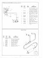
EXHAUST
GROUP
4
,.,..,,,,,
,,
.:.
,,
b
REF.
PART
NO.
——
NO.
I
‘MANIFOLD,
155C352
.!
,, j,
.,,
PART
QTY.
USED
—
‘:,
DESCRIPTIONS
EXHAUST
I
Horizontal
Outlet,
All
Except
,,
Key 6 (Specs.
2203 & 2537)
Vertical
Down,
Optional
Key 6 (Spec.
2203 Only)
Key 6 (Spec.
2537 Only)
Adapter,
Exh. Man. Out.
2
3
4
154D562
154C727
154D76i
155A 170
154A133
155A343
I
1
I
I
I
2
Gasket,
Gasket,
Exh.
Exh.
5
155B77
I
Muffler,
Exhaust
6
6A
7
I 550492
505-3 I
155A294
I
I
I
Tube,
Exh. - Flexible
Coupling,
Pipe
- Exh.
Plate,
Wall - Exh. Tube
4:.
:~
23
~
Adapter
Manifold
i, }\\
,,
,0
‘,’ I
///,
,:-=
,ti
Lb
\
.,
..“
,,
....’,
.--.l
~
Tube
~
.:.
,,
,~,
“ 6
\,’ <
6A
,.! .’;
>
..:>’
~..;’;
.-,
t
,, ,’”
&3
,\’1
/’
,,...
7“
7
\
.,
,’
,,,
/
,,,
.,
,>
/
‘$
0,
~]
. ..+
..
I
,
,.. -
/m
5 ---
.,,
,..,.,
;,,
,
,>
7Q
‘“~’,
1 /111./
I
~s!!::_
p’”
‘
“1
,T,”
J,,
,?”}
/
8
I “’. +-” ,65
la
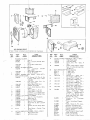
AIR
Note:
HOUSING
Shutter
HOUSING,
134D394
BLOWER
I
I
134D462
I
134 D1228
I
134D503
2
3
4
are
listed
but
SCROLL,
134D396
BLOWER
I
I
I
134 AI095
134B397
PANEL,
BLOWER
GRAL
CRANK
134E999
not
%1
illustrated.
u
PART
QTY .
USED
PART
NO.
REF.
NO.
l<”
GROUP
components
DESCRIPTIONS
K~Y
2537)
1,2,3,4,6
(Except
Spec.
17
Key
6 (Spec.
Key
5
2537
18
HOIUSING
1,2,3,4,5,6
K~y
Spec. 2203)
LPG
2203
7
8
9
10
II
134A I 169
134D423
I
I
134B47
I
I
Pits.
&
Crank
Baffle
Baffle
134B398
I
134B399
I
Pjate,
Plate,
134 B402
134B403
I
I
Extension,
E~tension,
SHROUD,
134 B437
LEFT
Only)
-
Opening
- L.H.
- R.H.
L.H.
R.H.
134D458
I
RIGHT
I
134D4S9
I
Begin
13
134D576
134A487
I
2
Kby 5
Biracket,
14
517-9
15
CATCH,
134B414
SHROUD
I
134A413
I
I
B~egin Spec.
B1
P lug,
Repl.
for
I
134 C1219
I
23
134 C1220
26
SPEED
GRIP
Left Hand Upper
Cover,
Gov.
Arm
Only
Plate,
- Pre-1
-
Spec.
Support
Housing)
1/4+20,
I /4-20,
Thin
Thick
I
Key 6 (Spec.
Shrcud,
Cyl.
2428 Only)
- Lower
R.t+.
I
Key 6 (Spec.
Elbow,
Air
I
Key 6 (Spec.
2428 Only)
Shutter,
Auto.
- Air Discharge
134 C1208
(opt.
134C884
6-1/2”
Spec.
134D893
I
134C880
I
A ONLY
Lower
44
2428
Outlet
Only)
Adapter
Accessory)
Applies
Long
After
Incl.
Parts
Marked
* Plus
Hdw.
*Extension,
Air
Discharge
Adapter
*Plate,
Mtg.
Vernatherm
Shutter
Element
I
*Shaft,
134 B660
I
I
I
I
* Bracket,
Vernatherm
*Element,
*Spring,
*Spring,
Vernatherm
Vernatherm
Shutter
I
I
3
*Switch,
High Air Temp.
*Strap,
Switch
Grdg.
*Clip,
Lead Securing
Cutoff
*Lead,
Circuit
309P77
160A I 44
332-47
336A 1090
——
.—
I
Switch
&
to
-
Repl.
Shutter
1958-
-
Only to
Assy.
134A885
309P85
134A656
134A658
-itr. Tube
Dur-
I
134 C1221
134C892
(Blower
A
- Begin
- Upper
L.H.
2428 Only)
- Lower
L,H,
2428 Only)
- lJpper
R.H.
1,2,3,4,6
- Begin
Crank
,--
A ONLY
5/16-48
Shroud,
Cyl.
Key 6 (Spec.
Shroud,
Cyl.
Key 6 (Spec.
Shroud,
Cyl,
Plate
Plate
A ir Out.
—
22
25
Fasteners
- SPEC.
FAS TENER
R ight Hand Lower
I
21
2
2
4
I
24
Cyl.
Cyl.
B, Key
Shroud
L ,eft Hand
NUT,
870- I I O
870-1 I I
870- I I 4
134 C1218
-
B
Button
20
Fasteners
HAND
CYLINDER
Spec. A - Incl.
Spec.
I
FASTENER
- SPEC.
Right
Hand Upper
Spec.
C & Discontinued
ing Spec. G
- Spec.
Baffle
Baffle
PARTs
DESCRIPTION
Used
HAN@ CYLINDER
I
Spec. A - Incl.
SHROUD,
134B438
12
1926266
Key
LPG
Pits.
(With
Prov.
M~g. Vaporizer)
Key 6 (Spec.
2203 Only)
Adapter,
Air Outlet
Cover,
B~Only
CATCH,
SHROUD
134A41 I
I
134A410
I
150C454
I
(Except
K~y6
(Spec.
2203 Only)
G1ille,
Air Outlet
r
HSG.
FRONT
- WITH INTE
(Spec.
QTY .
USED
Only)
134E408
5
6
NO.
A
GUIDE
I
A I Except
I
PART
NO.
——
16
Spec.
6
134 BI020
REF
Pin
Assy.
Mtg.
Power
Element
Stop
_....
2!
23
22
&
T
24
1
GG
,*,,
0
Q&
Q-” D-” “ ‘“’
Q
>*
17
“
*
.::*
*
_-~?
m
,
,,
,**’
*?
#
18
;,
*
20
19
,.
GENERATOR
GROUP
L
REF.
NO.
PART
NO.
——
*
I
2
I
5 10A52
*
I
4
*
*
i
I
9
*
4
10
*
I
13
.—..
~.
I
3
II
BRUSH,
2 14A45
COMMUTATOR-
214A57
214A49
4
4
COLLECTOR
8
8
4
BRUSH,
2 14A46
2 14A54
PART
QTY.
USED
15
212 BII06
4
16
212BI
123
8
17
212BI
120
4
18
GUIDE,
COMMUTATOR
212AI
121
4
212AIIOI
4
DESCRIPTIONS
Armature
- Incl.
Brg.
& Drive
Disc
Bearing,
Ball
Armature
(Rep].
510A2)
Frame
- Machined
& Drilled,
Less Coils
& Pole Shoes
Coil Set, Field
-Set
of 4
Coil,
Commutating
(Interpole)
Key 5
Shoe, Pole
Rig
Assy.,
Brush
Brushes
& Springs
Spec.
Begin
Key
A, Key 1,2,3,4
Spec. B, Key
-
QTY.
PARTS
REF.
PART
NO.
NO.
USED
DESCRIPTION
RING,
INSULATOR
I
-BRUSH
GUIDE
Spec. A, All Key
19
213BI06
213 BI16
20
21
I
213115
SPIDER,
BRUSH
I
212 BII19
I
212 BI 138
BELL,
211D76
Begin
I
Key
RIG
I
211D91
I
211D90
211 A140
I
I
Incl.
1,2,3,4,6
COVER,
232A60
Use 6)
Spring,
232A
23
B (Some
Pits.
BEARING
I
I
Commutator
Brush
BRUSH
Key 1,2,3,4,6
Key 5
24
232B 1093
232BI
162
232B84 I
25
26
232A6 15
232C784
* - Order
by
I
I031
COVER.
232B814
232 BI089
Spring,
Coil.
Ring
Brush
(Some Pits.
Use6)
Block,
Holder
- Co Il.
Ring
Br ush
part
1,2,3 ,4,6
5
MOUNTING
Spec. A, All
Begin
Spec.
Key Nos.
B, Key 1,2,3,4,6
Spec.
Begin
Key Nos.
B, Key 1,2,3,4,6
A, All
Spec.
(Except
22
Nos.
E$ Key
END
5
RINGSpec. A
Begin
Spec.
Spec.
END
Spec.
Key 5
Key6
(Spec.
Key
Spec.
2206
-’Top
&
5 (Key6,
2
I
I
Key
I
description,
Only)
(Except
OPENING
Key 1,2,3,4,6
I
2206
Key
1,2,3,4,6
2206)
BELL
3
I
2206)
5-
Spec.
Sides
Top
Key 5- Lower
Left
Key 5- Lower
Right
Cover,
End
Bel I Opening
Key I ,2,3,4,6Bottom
Clip,
Bearing
Stop
Support,
Gen. Frame
giving
Only)
plant
Model,
Spec.
-
and
..
I
16
1A
.--’
CONTROL
REF.
No.
——
I
PARTS
GROUP
PART
~
QTY.
No.
REF.
PART
USED
—
10
BOX, CONTROL
301 !3857
I
I
301 D990
PART
QTY.
USED
332A464
I
Jumper, Term.
to Grd.,
I
2,3,4,6
Condenser,
Term.
- Key
Battery
DESCRIPTIONS
Spe c. A
Begin
Spec.
BThrough
D, Key
II
312A17
PARTS
DESCRIPTION
1,2)3,4
*
I
*
I
2
30 I B856
I
3
BLOCK,
332A254
332A419
1A
4
TERM.,
Ke4 6
Pa~el,
Key
Key
Key
TERMINAL
332A43S
Box
Ke~ 6
Coyer,
Control
LO.AD CONNECTION
I
I
MARKER,
Control
I
12
307 B40
I
Relay,
3,4,6
13
308-2
I
Switch,
Hand
Key 2,4,6
14
SWITCH
308-26
15
308-90
15A
308P
- Upper,
Box
1,2-To
Spec. E (3-7/8”)
1,2 - Begin
Spec. E, All
3,4,6 (6-1/4”)
- START
I
& STOP
Key 2,4-
I
BI!OCK
Key
1,2 - To
Spec.
E (M I,M2,
154
I
M3,~4)
332A434
5
I
MARKER,
332A437
TERMINAL
I
Key 1,2- To Spec. E (M I,M2.
M3, kO)
BLOCK
Key~ 1,2 - Begin
Spec. E, All
Key 3,4,6 (M 1,M2,M3,M4)
Key, 1,2 - Begin
Spec.
E, All
332A436
I
CONDENSER,
LOAD
TERMINAL
3 12A22
2
Spet.
A (Some
Beg~in
Spec.
Key~ 3,4
6
8
312P87
JUMPER,
PLANTS
332A439
332A440
9
332A484
TER;
. - VOLT.
2
2
3
16
17
18
(M I, M2,M3,MO)
Plants
Use
3)
‘%19
B
SELECTION
- l-PHASE
20
Key 1,2- To Spec. E
Key
1,2 - Begin
Spec.
E, All
Key 3,4,6
J urn per, Term.
to Condenser
Key
21
AMMETER,
CHARGE
302-58
I
302-60
I
I
306A28
RELAY,
STOP
307052
I
307 B253
I
307 B180
I
Key 2,4,6
Key 5
Relay,
Start
46
Key
2,4,6
Key 2,4Spec. A
Key 2,4,6
(Except
Pits.
With
Manual
Choke)
Begin
Spec.
B
Relay,
2,4,6
Reverse
332A222
TERMINAL
I
-
A
Disc.,
Key 2,4,6
Block,
Term.
332A406
Start
Hole)
Regulator,
BLOCK,
22
Spec.
Elec.
1,2,
2,4,5,6
- Begin
Spec. B
Rect.
Hole)
- To
(Mts . in
Repl.
Use 308A166
Key
2,4,5,6
Use
Began
During
Spec. J (Mts. in Round
305A I
I
Pos.
1,2,3,4,6
- Start - Key
or
1,
Key
Key
1,2,3,4,6
Sol.
Key
-Chg.
- Remote
- Key
Circuit
Control
2,4,6
3-Place
Key
Volt.
Current
5
- Key
2,4,
Spec.
A--
.
REF.
.%
PART
QTY.
~
PARTS
USED
REF.
PART
NO.
NO.
DESCRIPTION
PARTS
DESCRIPTION
QTY.
USED
I
23
332A333
I
MARKER,
24
25
26
2~lace
Spec.
TERMINAL
-
Key
2,4,6
-
I
Begin
B
BLOCK
332A438
332A483
I
I
Key
2,4 - Spec.
A
Key
2,4,6
- Begin
(5, AI)
332A426
I
Key S ( 1,2,3)
REGULATOR
- KEY
Spec.
Begin
(30-Ohm,
RESISTOR,
304-121
304-25 I
VOLTAGE
I
I
27
27A
RESISTOR,
304A256
304A483
CHARGE
3
I
- KEY 2,4
To Spec. H (6-Ohm,
Begin
Spec,
H (3
225-Watt)
28
309-:10
I
Switch,
Ign. Cut-Off
Oil Press,
(Opt. )
29
308-97
I
Switch,
A ( 10-Ohm,
Spec.
B
(4,5,6)
Spec.
I
I
308A 165
308A9
CABLE,
416A77
33
Key
Key
BATTERY
2
Key
2428)
B
By-Pass
30
301 C853
31
*
i
Cover,
6
::;
32
SWITCH,
3PTi0NAL
Ac
REMOTE
METER
’;:;:P
CONTROL
PANEL
Low
Oil
308-37)
COntrol
307 B597
I
Relay,
Choke
Key 4,6 Spec.
(Repl.
307B4)
pits.
with
36
30 I A974
I
37
323A207
I
38
301 A878
I
303-84
I
Start-Stop
Switch
Bracket,
For 308-90
Mtg. , Key 2,4,36
Switch
Only)
Receptacle,
Key
6 (Spec.
2206 Only)
Plate
Control
Box
Panel
Key 6
Rheostat,
Control.
,
volt.
Opt.
Key
& choke
circuits
%-
*.
EQuIPMENT
by
Order
and Serial
- STOP
Spec.
35
BOX - Key 2,4,
START
(Except
Key 6 (Spec.
2428 Only)
Cable,
Battery
Jumper,
2,4,6 (Repl.
416 AI)
_
press-switch
(Repl.
2,4,5,6
2
I
Watt)
- LOW
308A94)
416A38
4 16A4
5-
75-Watt)
- 6-Ohm,
(Repl.
34
2,4,6
10-Watt)
2,4
6
description
giving
Key
Disconnect
F Through
K
Not
used
on
manual
choke.
5
complete
Model,
Spec.,
Number.
GROUP
2
,’,
Lir
..,,,
,.*
m
.?Z:’G=3
..__y_
.. ...
,3
REF.
NO.
QTY .
NO.
USED
PART
DESCRIPTIONS
4
I
2
3
.
4
o
—.
Q
0
5
6
. ..’”
+—. —-..
85
‘\
,
,.
f
As
Req.
As
302P42 I
Req.
METER,
RUNNING
I
302-2 i 2
I
302-102
RESISTOR,
304P99
304P12S
308-12
7
CIRCUIT
320P18
320P19
320P58
325K2
320PS2
323 P184
8
323-23
9
323-1
10
323-9
II
302 B448
RUNNING
I
I
1
BREAKER
As
Req.
As
Req.
As
Req.
I
As
Req.
I
As
Req.
As
Req.
4,- ,
@
0
/.””
10
4/
0-20
0-30
O-35
0-50
Amperes
Amperes
Amperes
Amperes
(Repl.
302-5)
(Repl.
302-7)
VOLTMETER
302P420
I!i
5
AMMETER
302-335
302 P418
302P444
302P419
o
0
7
PART
O-150-Volts
(Repl.
O-300-Volts
(Repl.
TIME
- I 15-V
60-Cycle
302-40)
302-41)
50-Cycle
TIME
METER
230-V
46 O-V
Switch,
Selector
- Voltmeter
20-Amperes
25-Am peres
30-Amperes
35-Amperes
50-Amperes
Receptacle
Dup - 2-Wire
PIUS
Ground
- 15-Amp
Receptacle,
2-wire
Twistlock
20-Amp
Receptacle
- 3-wire Twistlock
20-Am p
Receptacle
-4-wire
Twistlock
20-Amp
Plate,
Meter Face
S~ARTING
REF.~
MOTOR
& CHARGING
GENERATOR
GROUP
PART
GITY.
PART
NO.
USED
DESCRIPTIONS
NO. l
—.
191P86
I
191AH6
I
191 PI05
I
*Motor,
Starting
Jumper,
Copper
**Generator,
(Not
Illustrated)
- 6-V
Starter
Connection
Charge
-
- Incl.
Reg.
6-V
I
I
I
I
191C90
511P37
512P25
5 15A7
191B91
or parts,
contact
Prestolite
starter no. from nameplate.
- For
service
or parts,
contact
generator
no. from nameplate.
THE
FOLLOWING
AS USED
ON
SPECIAL
MODEL
Note:
Control
are terminated
REF.
PART
NO.
——
No.
PJote:
For
Gen.
Key, Generator
Pul Iey
Bracket,
Generator
I
* - J$or service
**
Guard,
Belt - Charge
Belt,
Generator
Drive
Pulley,
Generator
service,
Delco
giving
service,
CONTROL
KEY
giving
6, SPEC.
PARTS
ARE
OPTIONAL
(Not
Illustrated)
output
leads
18S0 ONLY
box is wall
mtd.
in Junction
Box.
type.
AC
PART
QTY .
USED
DESCRIPTIONS
302-212
I
308-68
332A607
332A642
308A29
338C235
301 D1852
I
Meter,
Switchr
I
I
I
I
1
Block,
Term.
- 12-Place
Strip,
Marker
- Blank
Switch,
Start
Harness,
Wiring
Box, Control
Panel,
Control
Bracket,
Contro
301 B1853
I
301 C1854
I
301 B1855
508-26
I
I
508- I
I
508-8
I
330-28
330-6
I
Box,
I
Cover,
other
Box
I Box
Box, Resistor
Grommet,
Rubber
Bracket
Grommet,
Rubber
put Box
Grommet,
put Box
SERVICE
KITS
kits,
to the
refer
Running
Time
Run-Stop-DRDT
(3/8”)
Rubber
AC
Mtg.
Mtg.
(3/4”)
Out-
( 1/2”)
[3ut-
Output
AC
group
Output
for
Box
tie
part
in ques-
tion.
REF.
No.
,——
PART
NO.
168K56
525P90
QTY .
USED
—
I
As
Req.
525P
137
522K131
I
522K138
I
522K210
I
PART
DESCRIPTIONS
Gasket
Paint,
12-OZ.
Kit,
Plant - Complete
Touch-up
(Pres s. Can)
- Mouse
Paint,
Touch-up
16-oz.
- Green
Grey
Enamel
(Press.
Can)
Enamel
.
Overhaul
Kit,
Spec.
A Only
Key 1,2,3,4
Overhaul
Kit, Spec. Bthrough
J - Less
1,2,3,4
Fuel
Overhaul
Kit,
L
-
Key
48
Less
I ,2,3,4
Pump
Spec.
Fuel
Kit-
Key
K through
Pump
Kit
-
WIRING DIAGRAM #61 lC 505
SINGLE PHASE MODELS
PENN STATE GASEOUS FUEL
BEGIN SPECIFICATION
‘%”
.—
——— ___
____
_l
f
b
L
I
I
)
-1
,
PLANTS
I
I
--—...
49
—.
WIRING DIAGRAM #61 IC 506
THREE PHASE MODELS
PENN STATE GASEOUS FUEL
BEGIN SPECIFICATION
“L”
PLANTS
,,,
7
7,,-
, c K.”.,<.
w-.,,,
4’.
7
I
I
D3----
L’
)
1(111
J
,
50
.,7!
,%40.
(m
.
WIRING DIAGRAM
# 611B127
250 VOLT,
DC MODEL
MAGNET USE PLANT
II
&l
r
‘I—
__
0 ‘1
———Z -1
S7%R7_JNG
MOTOR
51
DIAGRAMS
ARE
SHOWN
FOR
STANDARD
PLANTS
BEGINNING
WITH
SPEC
LETTER
F,
DIAGRAMS
FOR
PLANTS
PRIOR
TO
SPEC
F
AND
SPECIAL
MODELS
ARE
AVA~LABLE.
GIVE
COMPLETE
MODEL,
SPEC
AND
SERIAL
NUMBER
AS
SHOWN
ON
THE
PLANT
NAMEPLATE.
f31_lczJ33
IC5
]
--
&JL
CW-3?.
/’1F
G68C*,63R11C
,,....
U.4RWFAS
.fl.ff.
$ MAGNF7D
,v$358.6zof.
@
WIRING DIAGRAM #611C283
SING”:EPHASEMODELS
~
SPECIFICATION
“F” AND “G”
~
l~L-’-= ‘ Ga+mms J\
52
... .
WIRING DIAGRAM #611C279
THREE PHASE MODELS
SPECIFICATION
“F” AND l’G”
I
;)11
I
1’
I
i--_________ -____” ________ ‘
i--(---~.
,.
+
53
I
---l!
-———
—J__
..
...
..
WIRING DIAGRAM #61 1C327
SINGLE PHASE MODELS
SPECIFICATION
“H”, “J”, “K”
(Also Penn State Gasoline Plants)
“.,
..-
1
,—----------
.
---J=CIM.
I
PM*SE,2
120-w
—
.
. . . .
.
.
. . . . . .
.
.l_.
..
... .,
’,1. s,.”..< ,/f#r”$”:?c7c_5959
.
“T--WA
G*’
u’r*E,
v.
M,
II
/
~1
. J’
——
...
.,
54
.—
WIRING DIAGRAM #611C 324
THREE PHASE MODELS
~!K!f
SPECIFICATION “H”, “J”,
(Also Penn State Gasoline Plants)
,=__2___,_.-_L=
>._===
=.:
.ILAF?NCS3
C“.*E
6MAGNE70
w;z?a
E2c..
———
J
70?<&ow+e5i~t,w
6 f 5CW’54,5S.C’WM
‘====------–==
====----------T----=
(RF,G-V%S7”--—__
[Itmuu
TT-T-==,–
*w
,(!/+
A,, z,.
.27
I
-
‘I:;-:W
VIEW.
–
–_
_
_
r
I
L______________
-
_-
1
————
.——
————
+-%
J
.a
1/
1+
\
fA!;c
;,TR
,
_
L=
BA77ZRY
_ _.
Pcs+
6 ti-G
,--
—----
____________
/
..
.
WIRING DIAGRAM #61 IC 331
SINGLE PHASE MODELS
~
PENN STATE GASEOUS FUEL
SPECIFICATION
“H”, “J”, “K”
PLANTS
r
II
.. ----
I
L
..
56
—
—— .-
DIAGRAM #611C325
THREE PHASE MODELS
PENN STATE GASEOUS FUEL
SPECIFICATION“H”,“J”, “K”
WLIUNG
I
—“*
—*
.——
Uml..
I
—______
-J
wnma
:
*ox
c.en(wmnjwm,c9r3
-L
_,”,L
● Qx
● nx
9M#CL!WPtWVSS,Wt9,,
CC. VER(L.3WER1
“,YD)B,5S
r&r,ycL
@-aw
I18w.
**Z
N9xnll?
mm+
: PLA7C
H$X01A#7,
1—m.
uri7-a4
I
f Ma*.
●*M
3m.
Co”B,
.,,.-.—.
.,s.,.—,
!.- I
w
I
I
1’
!/l
LJ 4+1
+“mr
u .0’7
m.r’r,.
30,b,5D7)
w
1-
.–
(0
m
.1111
PLANTS
. --------------.@–’
rf(ft
m
-J
I
J1 I
IT==+
J
57
1::,
/ / ’ ‘,,
.\
.
.——_—-.—
w)
-.
[-~’’’----’
(REAR
WE
[INSIDE
VIEW]
==%?uL
-@
I
;71!
1
L-_____
Ii
-______ -___ ’______ .,___,
I q-”
II
II
?11
,----,
::::,
// 1!2
A
—
6 OHMS
—
-L
,-
,-’
A
I
J
_J
7———
,.! VOLT
ELECTRIC
CH4YI
4P
I /“
~M4
.——
—
———
——.
j
ILJT
/
::
I
MAT’L.,4V7F:
CO N7RDL
CD K7ROL
cnw7m0L
co KrRoL
.
..-4
BQX
COVER (uPPFR)N530!C853
BOX
PA NEL(UPPCR)
N>30!C
BOX co /ER IL 0WER)N$30,B
.9P.
N,?.,.
,,.4
13 AFFLL
PLATE
N> F0,A8,S
z-mm:
B u 77UNS-.
Nrx,
7-34.
+mfiwEss
CHONE $MAGNETO
M>33e
99(
856
Ea05
‘f
‘1111
58
I
DIAGRAM #611C498
PHASE MODELS
PACIFICATION
“L”
nn State Gasoline Plants]
,“.
..
..—
,
._— ,-
WIRING DIAGRAM #61 1C499
THREE PHASE MODELS
BEGIN SPECIFICATION
“L”
(Also Penn State Gasoline Plants)
J if----=
~=
>--=-----
---== ==.
=_=_-_-.-_-.
/.s..
.,FW, =.===------------------------—————- T,, .—, .— .7..,. .7 —---—
,0,
.6
—...
—- —_—_______________
——
. . #. . . —,=-...
—____
,_J
1
L___-_~]
l’fifl~
,.
M47LN.ZC,
1’
-—
J
.
.
59
—
j-
t-
,