1
Service Manual
THE FISHER@
-6~
T H E
F I S H E R
©
CT<",!"
'\0>
••••
~o:·
0
Ej
:=
,0,.
'
VOlUM'
ro,())~
0,
lRe..e
BALANCE
..
11I11'''''11l
I
--
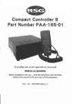
FM-190 X-190
C AUT ION:
This is a F ISH ER precision high-fidelity instrument. It should be serviced only by qualified personnel trained in the repair of transistor equipment and printed circuitry.
EQUIPMENT
AND TOOLS NEEDED
The following are needed to completely test and align modern high-fidelity
such as amplifiers, tuners and receivers.
Test
Instruments
Vacuum-Tube Voltohmmeter DC VTVM
Audio (AC) Vacuum-Tube Voltmeter (AC VTVM)
Oscilloscope (Flat to lOOkc minimum)
Audio (Sine-wave) Generator
Intermodu lat ion Ana Iyzer
Sweep (FM) Generator (88 to 108 mc)
Marker Generator
Multiplex Generator (preferably with RF outputFISHER Model 300 or equal).
Many of the items below are included just as a reminderthey are normal procedures, for experienced
technicians. Shortcuts can be taken but often they
cause additional damage - to transistors, circuit components or the printed-circuit
board.
Soldering-A
well-tinned, hot, clean soldering iron tip
will make it easier to solder without damage to the
printed-circuit
board or the many many circuit components mounted on it. It is not the wattage of the
iron that counts - it is the heat available at the tip.
Low-wattage soldering irpns will often take too long to
heat a connection - pigtail leads will get too hot and
damage the part. Too much heat, applied too long, will
damage the printed-circuit
board. Some 50-watt irons
reach temperatures of 1,000° F - others will hardly
melt solder. Small·diameter tips should be used for
single solder connections -larger
pyramid and chisel
tips are needed for larger areas.'
'
• When removing defective resistors, capacitors, etc.,
the leads should be cut as close to the body of the
circuit component as possible. (If the part is not being
returned for in-warranty factory replacement it maybe
cut in half - with diagonal-cutting
pliers - to make
removal easier.)
• Special de-soldering tiplets are made for unsoldering multiple-terminal
units like IF transformers and
electrolytic capacitors. By unsoldering all terminals at
the same time the part can be, removed with little
chance of breaking the printed-circuit
board.
• Always disconnect the chassis from the power line
when soldering. Turning the power switch OFF is not
enough. Power-line leakage paths, through the heating
element, can destroy transistors.
Transistors-Never
attempt to do any work on the
transistor amplifiers without first disconnecting the
- ~ AC-power linecord - wait until the power supply filtercapacitors have discharged.
• Guard against shorts - it takes only an instant for
a base-to-collector short to destroy that transistor and
possibly others direct-coupled to it. [In the time it
takes for a dropped machine screw, washer or even
the screwdriverrto glance off a pair of socket terminals
(or between a terminal and the chassis) a transistor
can be rllined.]
• DO NOT bias the base of any transistor to, or near,
the same voltage appl ied to its collector.
• DO NOT use an ohmmeter for testi ng transistors.
The voltage applied through the test probes may be
higher than the base-emitter breakdown voltage of the
transistor.
Output Stage and Driver-Replacements
for output
and driver transistors, if necessary, must be made from
the same beta group as the original type. The beta
group is indicated by a colored dot on the mounting
flange of the transistor. Be sure to include this information, when ordering replacement transistors.
instruments
Miscellaneous
Adjustable-line-Voltage
Transformer or
line-voltage regulator
Load Resistors (2) -8-ohm,
50-watt (or higher)
Stereo source (Turntable with stereo cartridge
or Tape Deck)
Speakers (2) Full-range, for listening tests
Soldering iron (with small-diameter tip).
Fully insulated from power line.
• If one output transistor burns out (open or shorts),
always remove all output transistors in that channel
and check the bias adjustment, the control and other
parts in the network with an ohmmeter before inserting a new transistor. All output transistors in one
channel will be destroyed if the base-biasing circuit
is open on the emitter end.
• When mounting a' replacement power transistor be
sure the bottom of the flange, the mica insulator and
the surface of the heat sink are free of foreign matter.
Dust and grit can prelent perfect contact. This reduces heat transfer to the heat sink. Metallic particles
can puncture the insulator and cause shorts - ruining
the transistor.
• Silicone grease must be used between the transistor and the mica insulator and between the mica and
the heat sink for best heat conduction. Heat is the
grea,test enemy of electronic equipment. It can shorten
the life of transistors, capacitors and resistors. (Use
Dow-Corning DC-3 or C20194 or equivalent compounds
made for power transistor heat conduction.)
• Use care when making connections to speakers and
output terminals. Any frayed wire ends can cause
shorts that may burn out the output transistors - they
are direct-coupled to the speakers. There is no output
transformer - nothing to limit current through the transistors except the fuses. To reduce the possibility of
shorts at the speakers, lugs should be used on the
exposed ends - at lea,st the ends of the stranded wires
should be tinned to prevent frayed wire ends. The
current in the speakers and output circuitry: is quite
high. Any poor contact or small-size wire,:,~~n cause
power losses in the speaker system. Use 14 ojl16 AWG
for long runs of speaker-connecting wiring.
DC-Voltage Measurements-These
basic tests of the
transistor circuitry are made without the signal generator. Without any signal input measure the circuit voltages - as indicated on the schematic. The voltage
difference between the base and the emitter should
be in the mi llivolt range - a sensitive DC meter is
needed for these readings. A low-voltage range of 1 volt,
full scale - or lower - is needed.
Audio-Voltage
(gain) Measurements-The
schematic
and printed-circuit
board layout diagrams are used.
Input signals are injected at the proper points - found
most quickly by using layout of the printed-circuit
board instead of the schematic. An AUDIO (AC) VTVM
connected to the test points should indicate voltages
close to those values shown in the boxes on the schematic. Many ot the signal levels in the input stages
are only a few millivolts-they
can not be read on the
AC ranges supplied on most Vacuum-Tube AC/DC Volt·
ohml!'eters (VTVMs). Even with a l-volt range a signal
level of 100 millivolts (.1 volt) will be the first 1/10
of the meter scale. A reading of 1 millivolt (.001 volt)
will hardly even move the meter needle.
'
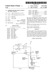
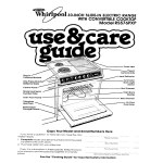
DIAL STRINGING
PROCEDURE
GROOVE
TOINNEA~
o
TO OUTER
GROOVE
its extreme clockwise
the remaining pulley.
• Hook one end of the spring over the bottom eor in the
front •• nd drive-drum (with the drum rotated to its extreme
counterclockwise
position).
• Stretch the tension spring until the loop on the free end
sticks out of the s lot in the edge of the drive-drum. Now
Insert a length of stiff wire, about l-inch long (0 piece of
straightened-out
paper clip will do nicely) through the loop
.to keep the spring stretched while stringing the dial cord.
Place the piece of stiff wire in the outer groove of the
drive-drumi bridging the slot in the drive·drum.
• Tie a small,
non-slip,
loop in the end of the dial cord.
i
Thread the loop in the dial cord through the opening in
the driveo/lrum slot, under the spring, and hook the loop
over the top ear inside the drive drum.
*
posi tion and fit the clio I corcl into
• Set the dial cord in the outer groove of the front-end drivedrum and thread it through the loop in the end of the tension
spring. (See detail drawing.ot lower right.)
• Pull all slack dial cord through the loop in the tension
spring •
• Check all pulleys
for proper threading
of the dial cord.
• Tie a small knot in the dial cord to secure it to the loop
in the tension spring. (Use a tweezer with a small tip to
help tie the knot.) Keep dial cord as tout as possible while
tying the knot.
• Apply a drop of quick-drying cement to the knot to prevent
it from slipping or becoming undone.
• Wrap the dial cord around the clrive-drum (counterclockwise) about
of a turn, in the inner groove, ond then around
the top guide pulley.
• After the cement has dried completely pull out the piece
of stiff wire and gently let the spring contract t9~Q.pply tension
to the dial cord.
.
..':'
• Stretch the dial cord to the left end of the dial, around
th.nwo guide pulleys and then back to the fly-wheel drive
shaft.
• Rotat. the front·end
clockwise position.
• Wind 3 full turns of dial cord around the.drive
shown in the upper detail drawing).
• While keeping
th" dial cord taut rotate
shaft (as
the drive-drum
to
.
. :~.
drive-drum ta its extreme'tbunter-
• Set the clial pointer to the zero (0) calibration
ging seale of the s Ii de ••.u Ie cliol.
on the log-
• Attach.the pointer to the dial cord and cement
with a drop or two of quick.dryin,ll cement.
it in place
If replacement parts are out of stock, locally, they may be obtained
directly from the Parts Department of FIStlER Radio Corporation.
They will be shipped "best way", either prepaid or C.O.D. unless
otherwise specified.
For instrument-operation information and technical assistance write
Richard Hamilton, Customer Service Department,FISHER Radio
Corporation, Long Island City, NewYork 11101.
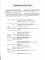
TROUBLESHOOTING
When 0 defect occurs in On electronic circuit the first
component suspected is usually the vacuum tube. Many of
the inexpensive tube testers will not indicate all the possible
~ internal faults in a voeuum tube - sli ght defects often sneak
past these testers. It is better to substitute another tube of
the same type.
Sometimes j t is possi ble
one circuit to another. This
when testing an individual
is switched with 0 defective
will be'ransferred
from one
to swi tch (transpose) tubes from
.method of testing is most suitable
stereo channel. When a good tube
One of the SOme type the symptom
stereo channel to the other.
GUIDE
When substituting
tubes it is absolutely necessary to be
certain the tube being inserted is ·good - a new tube, from a
fresh Iy opened carton, is not necessari Iy a perfect tube. Defects ",an occur from shipping and handling.
If you have any doubts about the quality of a tube try it
in an identical'eircuit
that is operating properly. For example,
a tube with heoter-eathode
leakage may operate normally in a
circuit with its cathode grounded; transpOSe (switch) it with
One in a circuit that has a cathode-bias
resistor and it will
cause a lot of hum.
• AC-interloek plug and ,..,eket, power cord and plug. wall outlet.
• Automatic shut~ff switch 51 (part of SELECTOR switch)
• Power switch 54.
• Automatic shut-off switch 51 (part of SELECTOR switch).
• J9 and its plug and the interconnecting
cable and the turntable
record player.
Distortion
Hum, Weak or
No oudio output
Check:
Test or.substitute
switch on the
• SPKR switch position and its operation.
VI. Test for proper DC voltages at: CR2, C2, R3; R3, R6, C3B; R6, R7, C3C;
R7, C3D.
• Setting of HUM ADJUST CONTROL (R2).
• 29S-volt DC 'power supply fi Iter (C3A, B, C, 0 ),
• Bios supply (CR3 and C4) for AC ripple.
DistortIon
Hum, Weak or
No 'Cudia output
(LEFT
ehonnel
Hum or
No audio output
(RIGHT channel
Hum or
No audio output
SELECTOR
Test (filament
only) SELECTOR In PHONO nod FM positions.
• Remove plug from Ll;FT RCRDR OUT jock, if used.
leakage for hum) Or substitute
VI, V4, VS.
only) SELECTOR in PHONO and FM positions.
• Remove plug from RIGHT RCRDR OUT jock, if used.
Test (fi lament leokage for hum) or substitute
VI, V4, V5.
in PHONO positions
•
•
•
•
Hum or
No audio output
SELECTOR
only
J3, J7, J9 and their plugs and interconnecting
cables to the record player.
Clean and tighten oil ground connections.
.
Reverse AC line-card plug in wall outlet
Reverse AC line-eord plug from record player in J18 (on chassis) if used.
in FM position only.
• Try other stations
• Reverse AC line.cord
plug in wall outlet.
Check:
Test (filament
• Antenna connections and antenna (outdoor)
leakage for hum) or substitute
Vll, V12, V13, V14.
Check:
Test (filament
• Balanced modulator 0401 and C409, C410; C407, C412i L401, L402.
leakage for hum) or substitute V401, V402.
.
HumNo audio output
Distortion
• IS. V402, C406, R433, R434, R43S, CR402, CR401.
• A li9nment of Z421.
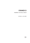
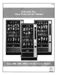
11131-2 MULTIPLEX
e
PRINTED CIRCUIT
IT
(JJ
------,
IR
C412
470
12K
MPX
~GENERATOR.
180
1
r---~
_J
I
IA
I ALIGNMENT
INSTRUCTIONS
MULTIPLEX SECTION
e
I
ALTERNATE ALIGNMENT
PROCEDURE
For multiplex generator. without an RFoutput
The pr.f.rred
aHgnment procedure,
in table 1 below, u••• a multiplex Slen.rator with, an RF output, lik.
FISHER Model 300. Optiml:lm performance
will b. obtained only when the multiplex decoder I. connected
the FM detector with which it will b. used. Check IF alignment ~irst-poor
alignment can prevent proper
plex decoder operation.
the
to
multi-
When uling this alignment procedure,
it i. nec.uary to disconnect
the ratio detector from the multiplex decoder
ot the point where the oenerator i. connected. Unsold.r point 1T carefully. The generator input must b. through
a simpl. low-pass f1l•• r-o 12 K resistor between the multipl."
generator and the MPX input with G 180 pF .capa.
citor from the MPX input
end of the r•• istor to ground (Figure 2, on schematic).
TEST
TEST
EQUIPMENT
REQUIRED:
MULTIPLEX
GENERATOR,
AUDIO <AC) VTVM. 100 kC OSCILLOSCOPE
TERNAL SWEEP JACKS, ALIGNMENT TOOL.
EQUIPMENT
REQUIRED:
WITH EX·
ITIPS
CONN.etION
1
2
MUI~rl:t=r::tor
onte.nna terminal,
19 kc outJIut of
generator te osdllo·
KOP' horizontal Inpvtl
generotor not c:ol'll'l.cf,d
to MPX I.dlon
3
Sa~
4
Some as Step 1
as Step I
MODULAtiON
19~rvlfot
---
GENIIATOR
INDICATOR
IF
TY"
DIVIATION
AND
CONHleTlON
ALIGNMENT
CONN_CTION
ADJUST
21 top and
bottom
---
Verti<:Qllnput of osc!lIoscope to A.22; set oscilloscope for ell:ternol Iweep
ZZ
VTVM and osdllolcope
vertical input to righT
. channel OIJlput lug
[termlnal1RI
ZI top
~o«J~~:n.r~:C:~~eO:n~~{o~~~~~
Same as Step 3
MPX separation
control (R-4'·
Mlnl:;U{;:a~~03dJIt£ 0be~Z~~~rnu~d
obtained In Step 3
Composite MPXr
1000 cps on
right channel only
±7S
kr;
5
Same as St~p 1
Same as Step 4
±75
kc
6
Same as Step '1
Composite MPX;
1000 cps on·
left dlaMel only
±75
kc
VTVM and OIcilloteope
vertical input tolrlght
channel output lug
(terminal IS)
Same 01 Step 5
--MPX separation
control {R41.
if nec.nary-
AUDIO
UVIL
INDICATION
VTVM to TP ~21
±75kc
INDICATOR
WITH EX.
Maximum
ALIGNMENT
IUPS
±7.5 kc
Compo'1te MPX,
1000 r;pl on
left r;hann.1 only
100 kC OSCILLOSCOPE
TAILI Z
TAIU 1
GENEIATOR
MULTIPLEX
GENERATOR,
AUDIO (AC) VTVM,
TERNAL SWEEP JACKS, ALIGNMENT TOOL.
1
readIng: on VTVM
CompOSite output of
MPX generator to
dem:cfvI~T~fr ~ti1nt
0:c1'1~:a;u:sndC:Z ~r:~.~~!~II;gto
38 kc. lInaious
pattern (see figure 11
should be as slow·
moving! en possible.
be
2
1)
19 kc outptJt of
generator to 01c1l10Scope horizontal Inputl
generator not etlnnected
toMPX settlon
TV" AND
CONNICTION
ADJUST
19 kc pilot
only
100 mV RMS
(2S0 MV poP)
AC,VTVM
to TP 0421
21 top Q~d bottom
---
---
Oscilloscope vertkol
Input to TP 422
ZZ
AC VfVM and oscilloscope
vertlc:ol Input to left
l:nonnel output lug
{f.rmlnal Jill
ZI top
3
SaM.
01
Step I
1000 cps on
left dlannel only
0.7 V RMS
13.92 V p·P}
4
Sam.
a. Step I
1000 cps on
right ehann.1 only
0.7 V ~MS
(3.92 V P'Pl
Same VlVM reading at obtained In
Step 3 ±:2 dbl clean 1000 cps sin.
wave on oscilloscope
5
Same al Step 1
Same al Step 4
M~:I;U;:a~~(ltJ"3b °be~~~fn~d
obtained In Step s.
6
Same as Step I
JOOO cps on
I.ft chonnel only
0.7 V RMS
13.92 V poP)
0.7 V RMS
(3.92 V p·P)
Some a$ Step 3
VTVM (llid oscillos,op.
••.••rticell Input to rlahl
ehonnal output lug
{terminal lSI
Sam.e 05 Step 5
MPX leparatlon
<:ontrol (R4~.
--MPX separation
control (R41.
ifneceualY-
INDICATION
Maximum
reading
on VTVM
o:c~tl~~~~u:sn~ro~: ~':~-~~~b\~gto
38 kc. llSioloul pattern [see figure lJ
should be as slowmoving as po"lble.
Maximum reoding on VTVMl clean
1000 cps line wave on os,IUoS'ope
Mlnl~ul~~~~atJn3b 0be~~~~~~~d
obtained In Step 3
Q'
be
Some VTVM reading
obtaln.d in
Step 3 :!:: 2 db; clean 1000 cps sine
way. on (ncilioitope
M~:i~ul~~3~n1
obtaIned
°be~~~~~d
in Step 5.
., I
lOOk.'
I
I
IL
_
-
.~
81 SELECTOR
I
OFF-SHOWN
•
•
•
'M STEREO
SWITCH
IN
FM MONO
I. 1'0111ALl.. VOLTAt! MID (:UMINT
MtASUltEM!NT In L.IM! VOLTAGI
T01l1VAC.
t.
MIAIUftitl·
WITH DC \lTV"
'ltITH NO atONAL INPUT .
lIl.lCTOfl •• ITCK IN ·'M MONO' 'OIITION.
DC VOLT"'E
TO ~eI!S
FlI STEREO F1LTEIt
"
TUIlt1l
,"OWlR
COMNECTOR
CAPACITORS
1.9" tolerance· for all fixed capacitor., un Ie•• otherwl ••
noted Or marked GMV (guaronf •• d minimum value). All
capac-Iton not marked uF are pF (uuF).
Symbol
Cl
C2
C3
Oe.crlption
M.ldo<l •• 01uF. 20l1. 600V
EI •• ,..lyll •• 100uF. 250V
EI.ctrolytrc,4-Sectlon
A-l00uF.250V
B- 40uF. 350V
C- 200uF. 350V
020uF,350V
PortNch
C2747
C50180015
C50180058
C4
C5
C6.7
ca. 9
Cl0.11
C12,13
C14.15
C16.17
C18.19
C20.21
C22.23
C2d
Electrolytic,
8uF, SOY
Mylar, .047uF, 2S0V
Ce;romh:, 33, N7S0, l000V
C •• oml •• 3900. 1000V
C.ramlc, 2200, lOOOV
Ceramic, 1800, 1000V
Ceramic, 68, N2200, lOOOV
C••• ml•• ,02uF. 20l1. 500V
C.ramlc, 39, N1S00, 1000V
Mylar, .022uF, 400V
. Mylar. ,012uF. 250V
M.ld.d, .0TvF. 20l1. 600V
C.629·138
C50197·52
C5~0015
C50072-34
C5OO72·5
C5007208
C5OO70012
C5OO89·5
C50070017
C50197.28
C50197-49
C2747
'0" tolerance for all fixed capacitor.,
unle •• oth.rwl.e
noted or mark.d GMV (guarante.d
minimum volue), All
capacitors not marked uF are ·pF (uuF).
Symbol
. Cl
C2
C3
C4
C5
C6.1
C8., B
C9
Cl0
CII
cn
C13
C14
CU
C16
In ohm., 5" tolerance,
1/3· W un I•••
K=Kilohm., M=Me;ohm ••
5ymbol
RI
R2
R3
R4
R5
R6
R7
R8,9
RIO, 11
R12.13
RId. 15
R16.17
Rl8A, B.
19., B'
Symbol
CR1.2
CR3
11
Jll
otherwl •• noted.
De-erlptlon
C.mposltlon.
820K. 10%, ~W
Pot., Wir.wound, 500, Hum Adj.
Compo.'tlon,
1.6K, 11m, lW
Compo,ltlon, 270K, Jo!Iw
Composition, 470K, Jo!Iw
Compo.itlon,
1.8K, 10", }iW
C.mp •• ltl.n. 3.3K. 10". ~W
D.p. Carbon, 820K
Dep. Carbon, 8.2M
Compo.ltlon,
18M, 10%, y'!W
Dep. Carbon, 1 K
Dep. Carbon, lOOK
Part Mo.
RC20BF824K
R516·128
RC30BFl52K
RC20BF274J
RC20llF474J
RC20BF182K
RC20BF332K
R33DC824J
R33DC825J
RC20IlFl86K
R33DC102J
R33DC104J
Pot., SOOK, Dual,
R50160013.8
Ba•• , Tr.ble
De.crlptlon
Olod., Silicon Rectifier
Diode, Silicon Recflfler
PII.t Bulb. #1847
Phono' .Jock
Part No.
5R50472
V·1112
150009·1
J846·120·1
R20
R21A, B
R22.23
R2d,25
R26, 27
R28,29
R30, 31
R32. 33
R34.35
R36A. B
R37. 38.
39,'40
Rdl •. 42,
43.44
R45, d6
R47.48
Rd9,50
PC1,2
51
52,3
Tl
T2
T3
Pot., SOOK, Balance Control
Pot., SOOK, Dual, Volume Control
Dep. Carbon. 22K
Dep. Car~on, 47K
D.p. Carbon, 3901('
D.p. Carbon, 1 K
Oep. Carbon, 220
Oep.,Carbon,47K
Compo.ltlon,
lS0K, 10%, KW
POL, lOOK, Duol~ AC Balance
R501600137
R501600139
R33DC223J
R33DC473J
R33DC394J
R33DC102J
R33DC221J
R33DC474J
RC20IlFl54K
RI078·116·
Dep. Carbon,
R33DC105J
1M
Oep. Corbon, 1 K
D.p, Corbon. 6.8K
Composition,
100, 10%, lW
Wlrewound, 50, 10%, SW
Printed Circuit, ·Tone Control
Switch, S.lector .
Switch, Slide
Trondormer,
Power
Tron.former,
Output
Transformer, Output
If replacement parts are out of stock, locally, they may be obtained
directly from the Parts Department of FISHER Radio Corporation.
They will be shipped "best way", either prepaid or C.O.D. unless
otherwise specified.
For instrument-operation information and technical assistance write
Richard Hamilton, Customer Service Department, FISHER Radio
Corporation, Long Island City, New York 11101. .
R33DC102J
R33DC682J
RC30lFl01K
R556·142
PC50187-9
51078-112
550200.5
TlO78-115
TlO78-11M
Tl078-117·1
Deecrlption
C.romlc, 21,5%, N7S0, 1000V
Ceramic, 1000, GMV, tOOOV
Ceramic, F •• dthru, 1000 GMV
Ceramic, 8, ±;SpF, NPO, 500V
C.roml •• 10. ±.5pF, Nl50. 500V
C.ramic~ Trimmer
Variable, FM
C••• ml•• 8. ±.5pF. NPO. 500V
Ceramic, 1000, GMV, 1000V
C.ramlc, 33, 5%, N750, l000V
Ceramic, 24, 5%, N150, 100DV
C.ramlc, 47, 5%1 N760, 1000V
C.,.ml •• 100, 5%. N1500. 1000V
Ceramic, F•• dthru, 1000, GMV
Ceromlc, 1000, 1000V
Port Ho.
C50070032
C5OO7lo2
C592·187
CC2OCJ080D5
CC20P Jl 0005
C662.123
C818·116
CC20CJ080D5
C5007lo2
C50070025
C5007008
C50070.29
C50070019
C592·187
C50072.3
Composition, In ohms, 10% tolerance,.Y.! Wau, unle ••
oth.rwl,.
not.d. K=Kllohm, M=Mtgohm.
Symbol
Rl.2
R3
R4
R5
R6,7
R8
R9
RIO
Rll
R12
D•• crlptfon
lOOK
470
820
150K
lK
T50
21K
lOOK
lK
GI•••• 3.3K. TOll, 7W
Symbol
11,2
Deacrlptlon
Lamp #1847
5t.reo Scan IndicatOf
Coli, FM Ant.nna
Choke ·1.5 Mlcrohenry
Choke, RF
C.II. FM RF
,Coil, FM Oscillator
13
Ll
L2
L3
L4
L5
Part No.
RC20BF10dK
RC20llF471K
RC20BF821K
RC20BFI54K
RC20BF101K
:mmm
RC20IFl04K
RC20BF102K
RPG7W332K
Part No.
150009.7
1501621·2
L818·1l3
L500660d
L629·180
L818-1l4
.5818.118
C17
C18
C19
C20
C21
C22
C23
C24
C25
C26
C27,28.
29
C30
C31.32
33
C34
C35
R13
Rid
RU
R16
R17
R18
R19
R20
C•• oml., 5000. +80 -29". 500V
Ceramic, 2700, lOOQV
C•• aml •• 5000 •. +80· -20l1, SOOV
C••• ml••. 02uF. GMV. 1000V
Electrolytic,
2.S.ctlon
A- 40uF, 350V
B- 20uF. 350V
Ceramic, 5000, +80 -2<m, SOOV
Ceramic·, 2700, 10aGv
Ceramic, 5000. +80 -20%, SOOV
C.raml •• 2700, 1000V
C.ra.II •• 5000. +80 -20l1. 500V
C5008906.
·C50072.17
C5i1089-6
C50071-6
C50180076
Ceramic, 330, 1000V
Electrolytic,
SuF, SOV.
C50072·1
C629·128
C.,amle. 5000. +80 -20l1, 500V
C••• mle. 560. TOOOV
C.ramlc, 5000, +80 -20%, 500V
C50089-6
C$OO72·14
C5008904
GI••••
150
47K
T5K
4.7M
Dep. Carbon', 470K, ~", l/aW
Dep. Carbon, 330K, 5", 1/SW
RPG3W561K'
RC20IlF151K
RC20IF473K
RC20lFl02K
RC20IlF473K
RC201'563K
RC20BP102K
RC201lF271K
RC20llFU2K
RC20IlFr02K
RC20BFl53K
RC20llF475K
R12DC47dJ
R12D.C334J
Choice, .68 Mlcrohenry
Choice, .~ Mlcroh.nr,
Choke, 3.3 Mlcrohenry
Switch, Selector
Tranlform.'1
FM IF
Transformer, FM IF
Coil, Limiter
Tran.,forme" Rdlo D.t.ctor
L50066·1
L50066·21
L50066 ••
SI194A113
ZZ662.117
%%2981
%%5021006
%%5.021009
560. lOll, 3W
IK
47K
56K
lK
270
R21
UK
R22
R23
R24
R25
R26,27
lK
QOOS9-6
C5OO72.17
C50089-6
C50072·17
CSOOSU
r
C408
.luF
I
r~---·
I
I
MPX
CONN.
R40S
10K
TO FM OETECTOR
I
C407
470
I
L401
20mH
I
I
L402
I
20mH
I
T.P.421
I
I
I
R410
1M
'---
MONO OUTPUT
I.
I
1
R411
1M
R428
lOOK
1
HEAfERS
I
I
I
I
180V
LEFT
OUTPUT
RIGHT
OUTPUT
IZOV
120Y
I8llV
f05V
f85V
210V
20
TO ALIGN-METER
SWITCH
(NOT USEO ON ALL MOOELS)
I
I
n@@A
10 1! IF
,. lile
I$l@@
@@I$l@
,.
llC1L1MtH
IMOI"A4l2.
C401-C412
CR401-CR402
L4CleL402
D401 .
P811SICIIS
~
~
VOLTAGES
lH 101
@
,p
~
CAN VARY t20'Ilo
STEREO
MONO
I PARTS
DESCRIPTION LIST
I
Ail clrCl,Ilt c070nenti with .ymbol. btgl"nl~
with
.cOl Or. locat. on the prlnt.d·clleul,
board;
0" be·
ginning with ,042' at. mounted on the metal .ubehanl ••
~APACITORS
M tolerance
for all fhced capaclt~.,
unl.ss oth.rwls.
no,.d·or mark.d GMV (guaranteed minimum volw).
All capacitor.
not marked uF ar. pF (uuf).
Symbol
D•• crlptlon
C401
C402
Capacitor, Mylar, .047uF 10% loDV
C~pacltor, Polystyren.,
2700 5"
12~V
Capacitor, Plastic Film, .1uF
C4Q3
Capacitor,
Capacitor,
C.r. Disc.,
Pla.tlcFllm,
1500, 10"
1uF 20"
·2SOV
C406
Capacitor,
Plastic
C407
C408
Capacitor,
Capacitor,
~09
C410
C411
Capacitor,
Capacitor,
Copacltor,
C412
C421
C422
Mylar, .•027 uF, 511. IOGV
C.r. Disc, 470 pF .1~
Plostlc 'Ftlm,.luF
20"
2SOV
CAr. Disc, 820 10"
Cer. Disc, 820 10%
Pla· •.•lc· F·i1rn, .1i.1F 2OlJ'
2SOV
..
_.
-'
C.r. Disc, 470 pF, 10"
Poly~tyren.,
-'-", "._',
.~~
-',:-'--
18~, 5", SOOV
_-
..
CS08574·s
C50B634-20
C50B633·1
CSOBS76-4
CSOB633·1
Film; .033uF
2OlI400V
Capocltor,
D•• crlptl.oh
._._-'.
CS08633·3O
CsOBS76·1
C50B633·1
C50BS 76-3
CSOB576·3
CSOB633-1
CSOBS76·1
C50B57406
CsOB634-1
PD,tHo.
Poly.tv''''., 4700, 5", 12SV
5"",
Poly.tyren.,
220,
SOOV
Poly'styrene, 4700, 5%, 12SV
C.ramic, .02 uF, +80, _20%, SOOV
Caramlc. 2200, 301I, 1000V
Ceramic,
Ceramic,
100, 20", l000V
1200, 10%, 1000V
C••• mlc, 68, 10" NPO, 1000V
Mica, 4700, 5", 300V .
C.ramlc, 5000, 20", SOOV
Ceroml~, 39, 10", H1500, 1000V
CSOB634-21
CSOB634-2
C50B634-21
CsOOS9-4
0
C5i83-1
C5 83-9
C~ 83-S
C5 711,46
CS0332-7
CSOOS9-1
CS007O-17
RESISTORS
Port No.
20" 2SOV
C404
C405
Symbol
C423
C424
C42S
C426
C427
C428
C429
C430
c;431
C432
C433
Symbol
R401
Description
R402
Re.lstor,
1/8W
Reststor,
R403
R404
Resistor,
Resistor,
PartHo.
Dep. Carbon, 33k 5",
Rl~pC333J
Dep. Corbon, 1.5m, 5",
1I3W
R33DC155J
Compo.ltlon, 22M~ 10", ~W RC20BF2~6K
Dep. Carbon, 470k; S",
I/SW
R12DC474J
R40S
Re.i.tor,
R4.06
R•• lstor, D.p. Carbon, 470k, S",
R407
R.sistor,
D.p. Carbon, 470k, 5",
1I8W
Rl2DC474J
1I8W
RI2DC224J
o.p.
Corbon, 22k, 5",
l/SW
R408
R.slstor,
R12DC223J
Dep. Carbon, 22k. 5",
·l/sW
R409
R.sl.tor,
R4io
Re.lstor,
Rl~DC223J
o.p.
Carbon,
10k, 5%,
I/SW
lISW
R12DC103J
Dep. Corbon, 1m, 5",
R12DCIOsJ
Symbol
R411
R412
De.crlptlon
R.al.tor, C.p. Carbon, 1m, 5%, '/8W
R•• I.tor, D.". Carbon, 10k, 5%,
R421
R422
·R423
R424
D.p. Carban,
Oep. Carbon,
D.p. Carbon,
Potet'!tlometer,
Con·trot
Cep. Carbon,
ComPosition,
3.9K, 57\. ~1/3W
10M, 10"", 1I2W
Dap.
Dap.
Dep.
Dep.
23OK, 511, 1I3W
lOOK
1.5M, 511, 1/3W
47K, 5", 1I3W
R42s
R426
11427
R428
R429
R430
R431
R432
R433.434,
435
I/SW'
2.21,4, 5%; 1I3W
10K, 5%, 1I3W
lK, 5", 1I3W
5K Separation
PartHa.
R12DC105J
R12DC103J
R33DC225J
R33DC103J
R33DC102J
Dap. Ca. bon, ISO, slI, 1I3W
R5015o-11
R33DC392J
RC20BF106K
R33DC224J
R12DC104J
R33DC15sJ
R33DC473J
R12DC6S3J
R33DC151J
Composition,
RC30BF333K
Carbon,
Co.bon,
Ca.bon,
C•• bon,
D.p. Corbon, 68K
IND1CA:TOa
AMPLIfiER
AND
3llKC
I Iel· Ie~:~~I~~
OSCILLATOR
33K, 10%, lW
MISCELLANEOUS
Symbol
CR401
CR402
CR421
D401
L401
1.402
L421
1421
1422
MPX 120
D.ser I'ptlon
Dlod.
Dtod.
Diode
Ring Demodul~r
Coil
Coli
Coli, 20 uH
Tronsformer, 19 kc:
T.ransformer, 381cc
Printed Circuit Bd.
MinI. Pin Term.
51.evlng 23--32" Lg.
Z421
Z422
Part Ne.
Vl1'1W
V50A26Q.15
V1l12
V50A26o-18
L50334-2
L50334·2
Ls0334·2
ZZS0210034
ZZ502100S4
PB1'131B111
A50A577
E~OA684-4
ECC81
ECC83
12AT7
12AX7
.&
.,....
".
3901<
...
r~~
'.,1<
ca •
•OUUF
N.
'"
••
,
*.OOV
,,8f€2
It" .•.
lOOK
'"
~.""
lAC BA"
8ALANCE
CONTROi.
mJ
[E]
IPHONO!
~
OUT
"
...
~:~
I
S2B
HIGH
FILTER
I
SW
OFF
"
r---....,
..
I
8AS,,-
1201C
750
I
L-L1t- .JI
..........
r·I
"'8a
[
••" J
III
'17
.02UF
RuI
••,
IIII'B
L~
CI5llF
21k
3000
l
TREBLE
I
J
L.::
PC2
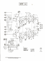
NOTe::
I, ALL VQL1lI4ES MEASUR£O WITH 'VTVM
AT I nV.AC I.lfl£. NO Sl6NAI. INPUT
2.*VOLTAGf
'VAlIIlr:J WITH
S. ALL call'AOTOIl:!1
NOT
AU
MARKED
4.VOI..T.AQES .M£ASlRt£O
WITH
WU
O!Cfl£"'E
SLIGNTLY
PoS
AIl:E
Sf SELECTOR SW
PI" lUUFJ
TUNER OFF
WITH TUN[R
ANO
ON
I
PHONO
2
FM
3
AUX
-
SHOWN
IN
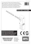
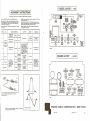
I ALIGNMENT
iet the SEL.ECTOR
switch
Adjust lino voltage (power
AC SO to 60 eye I•••
to the MONO pOlitlon.
S.t tuning dial to tho extr.,me low-frequency
pOlltlon.
.Dial pointer
should line up with the calibration
mark
It the low-froquoncy
end of the dial scal •• ROlot tho
~ial
pointer
if
and the
t •• t
equipment
Repoat steps
and maximum
for at loost
4 and 5 to obtain
sensitivity.
proper dial
s
AND 381<C
OSCILLATOR
~
Z421
Z422
SIGNAL GENERATOR
DIAL
GENERATOR
COUPLING
DC VTVM
MOD.
Tl; T2, T3,
Tut Point 3*
Unground.d tu be
-
.hl.ld
of V2
Un5lround.d tub.
2
,hl.ld
of V2
10.7 MC
None
10.7 MC
.
None
Ho •. I.ud of DC VTVM
to TEST POINT 4.
Ground I.ad of DC
VTVM to i unctIon of
two •• rl •••. conn.ct.d
eXf.mal r•• I'for •
(47K S%), wlr.d boo
~~d~o~~~:
I
90 MC
4
106 MC
;
S
98 MC
90MC
Two 120·ohm
carbon resl.ton
In •• rI•• with
g~.rotor I.ocl.
to the ani.nno
t.rmlnals
(Flour. l).
Moxlmum
.
valtog8
(b_low 20 volt.)
ECC8s8n
6AQ8
~U
Zl
106MC
o'
400 co ••
±22.S KC
d••••lation
0'
400
98 MC
OSe·MIX
0'
400
ep ••
ECC83
12AX7
3RD IF
Z2
6HS6
Z3
EF94
6AU6
Z4
RIGHT LEFT
~
OUTPUTS
Z.ro Indication on
nro"c.nt.r
dial.
POINT 3
Through lOOK
r.slstor to
Tut Point 2
L5 and L4
Through lOOK
r•• i,tor to
T.st Point 2
C7 ond C6
e •.•••
±22.S KC
d••••latlon
I9KC PILOT
SIGNAL
AMPLIFIER
~AND
2ND
EF94
6AU6
AND
T5 top
C,NTROL
$ G $ [~:t@)~
G
negotl ve
L-RFAMP
±22.S KC
deviation
3
T4,ond Ts
top and bottom
LAMP
~
INDICATION
1ST
FREQ.
I
S.t dial
pointer for
extreme
low·frequency
position.
ADJUST
TEREOSCAN
STEREO
SEPARATION
r;1 U
~ LJ~
~
LJ
calibration
ECC81
12AT7
STEP
I
R4
input to c:ha •• i•..
) for 117 volt.
(Use only the proper, fully insulated,
alignment
tools.)
'Reduce signal generator output during alignment to k.ep
VTVM reoding below that specified
for step 1.
necessary.)
Narm up the chauis
15 minutes.
I
INSTRUCTIONS
Through lOOK
r•• lstor to
T.•• t Point 2
I CHASSIS LAYOUT
•
I
AMPLIFIER
Adl"'t for maxi·
mum n.gatl ••••
voltog. and check
for sinusoidal
wav.form, with
seop., ot LEFT
or RIGHT outPl,It.
Ll
CHA:~~t6RIVER
O0
AND01NV
eHAN~~rTDRIVER
.'
.
LEFTAND RIGHT
INPUTAMP
ECC:QINV
'.:.J
~ECC83
12AX7V
~;2AX7
$~~99o
I
000-,I
INT sPKRS
r-
RIGHT COM
lEFT
RIGHT PUSH·PULL LEFTPUSH·PULl
POWEROUT
POWER OUT
ELL80@
ELL80@
6HU8
6HU8
:lo..
@@~~
l 1 J
FM
RI~rT
FM
~EI)T


![10780-90006 - 10780A Laser Receiver for 5501A [Prefix 1948] (Mar](http://vs1.manualzilla.com/store/data/006009643_1-6e2f54ebb2199ef6df634558ba4c1bb6-150x150.png)