1
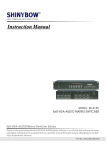
AV-OL-ILAB-12-R-D
& AV-OL-FL810-12-R-D
Universal DC Low Intensity Obstruction Light
Dual Fixture
Installation & Service Manual
Version 1.0
Universal DC Low Intensity Obstruction Light
Dual Light Fixture
Table of Contents
Introduction...........................................................................................Page 4
Technology............................................................................................Page 4
AV-OL-ILAB-12-R-D & AV-OL-ILAB-12-R-D Models...........................Page 5
Safety Information................................................................................Page 8
Unpacking, Mounting, Wiring & Setup...............................................Page 8
Unpacking....................................................................................Page 8
Mounting......................................................................................Page 8
Installation & Wiring.....................................................................Page 8
Opening & Closing the Light Head.............................Page 9
Operation & Setup.....................................................................Page 11
Intensity & Operation Mode Setting..........................Page 12
Alarm Relay Output..................................................Page 13
RS232 & RS422/485 Communications (Optional)...Page 13
Optional GSM Monitoring & Control System...................................Page 15
Maintenance & Servicing...................................................................Page 16
Trouble Shooting................................................................................Page 17
Appendix.............................................................................................Page 18
Light Head Wiring Diagram.......................................................Page 18
Light Head Systems Diagram....................................................Page 19
Light Head Parts Diagram.........................................................Page 20
Main Enclosure Parts Diagram..................................................Page 21
Product Order Codes.................................................................Page 22
Certifications & Compliance......................................................Page 23
Avlite Light Warranty..........................................................................Page 26
Version No.
1.0
Description
Manual launch
Date
Mar 2015
Approved
W. Evans
Latest products and information available at www.avlite.com
3
Universal DC Low Intensity Obstruction Light
Dual Light Fixture
Introduction
Congratulations! By choosing to purchase an Avlite light, you have become the owner of
one of the most advanced solar LED obstruction lights in the world.
Avlite Systems draws on more than 25 years experience in the design and manufacture of navigation aids,
and particular care has been taken to ensure your light gives years of trouble free service.
As a commitment to producing the highest quality products for our customers, Avlite has been independently
certified as complying with the requirements of ISO 9001:2008 quality management system.
By taking a few moments to browse through this booklet, you will become familiar with the versatility of your
light, and be able to maximise its operating function.
Please remember to complete the Avlite warranty registration card accompanying your light.
Technology
Avlite Systems is a world-class solar lighting systems manufacturer with a proven
reputation for rapid, innovative, and agile technology solutions designed specifically for
defense, government, civil and humanitarian aid operations in the most remote, toughest
environments.
Electronics
Avlite employs leading in-house electronic engineers in the design and development of software and related
circuitry. All individual electronic components are sourced directly by Avlite procurement staff ensuring that only
the highest quality components are used in our products.
LED Technology
All Avlite lights use the latest advancements in LED (Light Emitting Diode) technology as a light source.
The major advantage of LED’s over traditional light sources is well established in that they typically have an
operational life in excess of 100,000 hours, resulting in substantial savings to maintenance and servicing costs.
Precision Construction
Commitment to investing in the design and construction of injection-moulded parts including optic lenses, light
bases and a range of other components ensures that all Avlite products are of a consistent and superior quality.
Optical Performance
Avlite manufactures a range of aviation LED lenses moulded from multi-cavity dies. The company has superior
in-house lens manufacturing capabilities to support outstanding optical performance.
Award-winning, Patented Technology
Several United States and Australian patent registrations are held on Avlite’s range of innovative designs, with
other regional patents pending in Canada, United Kingdom and Europe.
Latest products and information available at www.avlite.com
4
Universal DC Low Intensity Obstruction Light
Dual Light Fixture
AV-OL-ILAB-12-R-D
& AV-OL-FL810-12-R-D Models
This Avlite dual light fixture is a steady burning, low intensity LED obstruction light
designed to comply with FAA L-810 and ICAO LIOL Type A & B requirements. The
model can be used for marking obstacles up to 45 metres above ground, such as
telecommunication towers, wind turbines, buildings and other tall structures.
Avlite’s LED obstruction lights offer an ultra bright, energy efficient and cost
effective lighting solution.
The dual light fixture can be configured to different operational states. Both light
fixtures may be set to operate steady-burning. Alternatively, the dual light fixture
may consist of a main light and a standby light. If the main light should ever fail the
standby light will automatically switch on to ensure the obstacle is always clearly
marked.
The light fixture incorporates internal diagnostic checking and an alarm contact for
remote monitoring. The alarm relay is energised in normal operation and is released
whenever the LED is not lit.
Latest products and information available at www.avlite.com
5
Universal DC Low Intensity Obstruction Light
Dual Light Fixture
Combined visual &
infrared for visibility to
pilots using night vision
(optional)
Single LED Optic
Automatic night
operation
Tough UV-stabilised
LEXAN® polycarbonate
lens & light base
2.83in
72.0mm
Robust 7-stage
powder-coated
aluminium housing
8.58in
218.0mm
10.32in
262mm
18.95in
481mm
Latest products and information available at www.avlite.com
6
SPECIFICATIONS•*
12-48 VDC
Light Characteristics
Light Source
Available colors
Peak Intensity (cd)†
Horizontal Output (degrees)
Vertical Divergence (degrees)
Reflector Type
Intensity Adjustments
Operation Mode Adjustment
LED Life Expectancy (hours)
As tested;
ICAO: AV-OL-ILAB-12 (Type A) & AV-OL-ILAB-12 (Type B)
FAA: AV-OL-FL810-12-R LED
Red as standard. Other colors available on request, including IR
Complies with ICAO LIOLA & LIOLB and FAA L-810 obstruction lights
360
ICAO Model: as per ICAO Type A/B specification
FAA Model: as per FAA L-810 obstruction light specification
Single LED Optic
ICAO Model: User-adjustable between 10cd & 32cd
FAA Model: 32.5cd
User-adjustable between dusk-till-dawn & 24 hour operation
>100,000
Electrical Characteristics
Current Draw (mA)‡
Power (W)‡
Current Draw (mA)‡
Power (W)‡
• Specifications subject to change or variation without notice
* Subject to standard terms and conditions
† Intensity setting subject to solar availability
‡ When used in redundant failsafe mode
Circuit Protection
Operating Voltage
Temperature Range
Failover Configuration @ 12V:
ICAO LIOL Type A @ 10cd Steady-on with relay energised: Imax = 55
ICAO LIOL Type B @ 32cd Steady-on with relay energised: Imax = 120
FAA L-810 @ 32.5cd Steady-on with relay energised: Imax = 120
ICAO LIOL Type A @ 10cd Steady-on with relay energised & IR: Pmax = 0.66
ICAO LIOL Type B @ 32cd Steady-on with relay energised & IR: Pmax = 1.44
FAA L-810 @ 32.5cd Steady-on with relay energised & IR: Pmax = 1.44
Dual Lit Configuration @ 12V:
ICAO LIOL Type A @ 10cd Steady-on with relay energised: Imax = 110
ICAO LIOL Type B @ 32cd Steady-on with relay energised: Imax = 240
FAA L-810 @ 32.5cd Steady-on with relay energised: Imax = 240
ICAO LIOL Type A @ 10cd Steady-on with relay energised & IR: Pmax = 1.32
ICAO LIOL Type B @ 32cd Steady-on with relay energised & IR: Pmax = 2.88
FAA L-810 @ 32.5cd Steady-on with relay energised & IR: Pmax = 2.88
Integrated
12 – 48 VDC
-40 to 80°C
Physical Characteristics
Body Material
Lens Material
Lens Diameter (mm/inches)
Lens Design
Mounting
Height (mm/inches)
Width (mm/inches)
Mass (kg/lbs)
Product Life Expectancy
7-stage powder-coated aluminium
LEXAN® Polycarbonate – UV stabilized
100 / 37/8
Single LED Optic
ICAO Model: 4 x 6.5mm mounting holes
FAA Model: ¾ inch pipe thread
ICAO Model: 262 / 103/8
FAA Model: 272 / 10¾
481 / 19
2.3 / 5
Up to 12 years
Environmental Factors
Humidity
Icing
Wind Speed
0 to 100%, MIL-STD-810F
22kg per square inch
Up to 240kph
Certifications
CE
Quality Assurance
EN61000-6-3:1997. EN61000-6-1:1997
ISO9001:2008
ICAO
FAA
Waterproof
Low Intensity Obstruction Light Type A & B
L-810 Steady-burning Red Obstruction Light
IP67
Intellectual Property
Trademarks
Warranty *
Options Available
AVLITE® is a registered trademark of Avlite Systems
3 year warranty
• Variety of solar/battery configurations
• GSM Cell-Phone Monitoring
• Dual visual/IR output
• IR LED
• RS422/485 communications port
Universal DC Low Intensity Obstruction Light
Dual Light Fixture
Safety Information
Safety Information
• Install the light in compliance with the effective local electrical code(s).
• Mains power should always be disconnected when work is being done in close proximity to
electrical fittings, and electrical work should only be done by a licensed and certified professional.
• Operate the light only within the indicated electrical ratings and product usage instructions.
• To ensure that the light and peripheral equipment function safely and correctly, use cable in
compliance with the effective local electrical code.
• Do not stare at the LED or shine the LED into your eyes or those of another person.
• Do dispose of the product according to the local laws and regulations for your region, for example,
at a recycling center that accepts electronic devices.
Unpacking, Mounting, Wiring & Setup
Unpacking
Unpack all hardware and inspect for damage. If there is any damage, please contact your Avlite Office.
Retain original packing material for possible future use in shipping.
Mounting
Mount the Obstruction Light using its four mounting holes. Make sure the light is horizontally aligned to
guarantee the required beam pattern of the obstruction light.
Installation & Wiring
Before proceeding with installation or service, make sure the following conditions are met:
• Ensure the tower or mast is grounded (No RF HAZARD)
• Check the mast lighting circuit is not faulty
• Ensure power lines are not ‘live’ (NO ELECTRICAL HAZARD)
• Avoid touching live circuits!
• Avoid touching any component or any part of the circuitry while the unit is operating. Do not change
components or make adjustments inside the unit with power on.
NOTE:
The unit must be installed by a qualified and certified professional.
Latest products and information available at www.avlite.com
8
Universal DC Low Intensity Obstruction Light
Dual Light Fixture
OPENING AND CLOSING THE LIGHT HEAD(S)
Remove the locking screw
In order to open the unit, the top half of the unit should be turned anti-clockwise with respect to the
bottom half. The top half will turn approximately 20mm over a positive “click” before separating from
the bottom half. Attention should be paid to the restriction caused by the internal cabling which is
secured by a cable gland.
The unit is closed by reversing the above procedure, ensuring the black rubber O-ring remains in
place.
Locking Screw
Figure 2. Obstruction Light head
DC POWER CONNECTION
1.Open the top lid by unscrewing the 6 top screws and removing the lid. Wire up the light and connect
power to the terminal block. Please refer to Figure 1.
2. Wire as follows:
• Positive supply (+) = +VDC
• Negative supply (-) = 0V
3. Close the lid using all 6 top screws. Make sure the black rubber O-ring remains in place during that
process.
NOTE:
• The unit is designed to operate from a nominal DC voltage from 12V to 48V.
• Use cable in compliance with the effective local electrical code. The cable outer diameter should be
between 5mm and 10mm. Avlite recommends the following number of cores and size[mm²]: 2 x 0.75
or 2 x 1.0
• Color coding may vary depending on country and local regulations.
Latest products and information available at www.avlite.com
9
Universal DC Low Intensity Obstruction Light
Dual Light Fixture
OV
Mounting plate
+VDC
Terminal
Block
Colour
CONNECTOR
SIGNAL
Brown
Terminal block
12V – 48V
Blue
Terminal block
0V
Dual lit wiring configuration
ry Light
Primary Light
SecondarySecondary
Light
Li
Mounting plate
0V
Terminal
Block
+VDC
0V
COLOUR
Brown
Blue
Mounting plate
Terminal
Block
+VDC
CONNECTOR
COLOUR
Terminal Block
Brown
Terminal Block
Blue
SIGNAL
CONNECTOR
12-48V
Terminal Block
0V
Terminal Block
SIGNAL
12-48V
0V
Fail-over wiring diagram
Figure 1. DC Wiring Diagram
Latest products and information available at www.avlite.com
10
Universal DC Low Intensity Obstruction Light
Dual Light Fixture
Operation & Setup
When powered up, the light will constantly check day/night status using its internal ambient light
sensor. The ambient light sensor averages its measurement for 30 seconds.
FAA: By default the lights turn ON when the ambient light decreases to not less than 35 footcandles (367.7 lux) and turn OFF when the ambient light decreases to not more than 60 footcandles (645.8 lux). These limits can be factory adjusted, if required.
ICAO: By default the lights turn ON when the ambient light decreases to not less than 35 footcandles (100 lux) and turn OFF when the ambient light decreases to not more than 60 footcandles (150 lux). These limits can be factory adjusted, if required.
ight
Latest products and information available at www.avlite.com
11
Universal DC Low Intensity Obstruction Light
Dual Light Fixture
INTENSITY & OPERATION MODE SETTING
Light intensity & operation mode setting for ICAO compliant light fixture
The fixture will be supplied with the ICAO compliant optic.
The obstruction light will be pre-set to the intensity setting specified by the customer (ICAO Type A or
ICAO Type B) for a red steady burning Low Intensity Obstruction Light in dusk-till-dawn mode. The
intensity and operation mode is pre-set in the factory and does not need to be set by the user.
If the customer should need to change the intensity or operation mode settings of the ICAO compliant
model they can do this by changing the INTENSITY DIP switch. Please refer to table below for DIP
switch settings and Figure 3 for circuit board location.
Position 2
Position 1
OFF
OFF
Light Intensity
ICAO Low Intensity Obstruction Light Type A (10cd), dusk-till-dawn mode
– DEFAULT
OFF
ON
ICAO Low Intensity Obstruction Light Type A (10cd), 24 hour mode
ON
OFF
ICAO Low Intensity Obstruction Light Type B (32cd), dusk-till-dawn mode
ON
ON
ICAO Low Intensity Obstruction Light Type B (32cd), 24 hour mode
Light intensity & operation mode setting for FAA compliant light fixture
The fixture will be supplied with the FAA compliant optic. The FAA compliant model comes pre-set to the correct intensity for L-810 steady burning red
obstruction light in dusk-till-dawn mode. The intensity and operation mode is pre-set in the factory and
does not need to be set by the user.
If the customer should need to change the operation mode settings of the FAA compliant model they
can do this by changing the INTENSITY DIP switch. Please refer to table below for DIP switch settings
and Figure 3 for circuit board location.
Position 2
Position 1
Light Intensity
No function
OFF
FAA L-810 Low Intensity Obstruction Light, dusk-till-dawn mode
– DEFAULT
No function
ON
FAA L-810 Low Intensity Obstruction Light, 24 hour mode
NOTE:
The ICAO Model and FAA Model have their own unique optic. The ICAO model cannot be used for
FAA purposes and the FAA model cannot be used for ICAO purposes. The model required needs to be
specified at the time of order.
NOTE:
The unit must be installed by a qualified electrician.
Latest products and information available at www.avlite.com
12
Universal DC Low Intensity Obstruction Light
Dual Light Fixture
ALARM RELAY OUTPUT
In normal operation the relay is energised
• Terminal contacts COMM and NC of the relay are electrically closed
• Terminal contacts COMM and NO of the relay are electrically open
Whenever the LED is not lit due to a power failure and/or a LED failure the relay will not be energised.
• Terminal contacts COMM and NO of the relay are electrically closed
• Terminal contacts COMM and NC of the relay are electrically open For location details of the terminals please refer to Figure 3.
The alarm relay can be configured in three different ways:
• Relay normal operation (default, as described above)
• Relay inverse operation (inverse functionality of the normal operation, used to conserve power)
• Relay disable (in case the relay is not required, used to conserve power)
NOTE: The alarm relay is intended for low voltage (SELV) connection only.
RS232 & RS422/485 COMMUNICATION (OPTIONAL)
The Obstruction Light offers a RS232 and a R2422/485 interface.
RS232
Typical 3 pin TxD, RxD and GND arrangement
RS422/485 Typical 4 pin arrangement with Termination selection and Duplex/Halfduplex selection
For location details please refer to Figure 3.
Duplex
SW3
Termination
SW4
S1
S2
S1
S2
OFF
OFF
Simplex operation
OFF
OFF
No termination
ON
ON
Duplex operation
ON
ON
120 Ohm termination
Please contact AVLITE for further details.
Latest products and information available at www.avlite.com
13
Universal DC Low Intensity Obstruction Light
Dual Light Fixture
Relay
INTENSITY
TxD
RxD
SW2
ALARM
GND
Figure 3. Obstruction Light PCB with terminals and DIP switches
Latest products and information available at www.avlite.com
14
NC
NO
COMM
GND
0V
POWER
FULL HALF
DUPLEX
RS-232
1 2
ON
ON
ON
1 2
1 2
TERMINATE
+VDC
GND
-VE
+VE
-VE
+VE
RS-422
Tx
Rx
Universal DC Low Intensity Obstruction Light
Dual Light Fixture
Optional GSM
Monitoring & Control System
The AV-OL Series Dual Light Fixture may also be fitted with GSM Cell-Phone Monitoring and Control
– enabling users to access real-time diagnostics data and change light settings via cell-phone. The
system can also be configured to send out alarm SMS text messages to designated cellular telephone
numbers. Users can also have alarms and reports sent to designated email addresses.
Please contact Avlite for further information and instructions.
Latest products and information available at www.avlite.com
15
Universal DC Low Intensity Obstruction Light
Dual Light Fixture
Maintenance & Servicing
Designed to be maintenance free the Obstruction Lights require minimal attention, though the
following maintenance and servicing information is provided to help ensure the life of your Avlite
product.
•
Occasional cleaning of the dome lens may be required using a cloth and warm soapy water.
Latest products and information available at www.avlite.com
16
Universal DC Low Intensity Obstruction Light
Dual Light Fixture
Trouble Shooting
Problem
Remedy
Light will not activate.
•
•
•
•
Ensure proper connectivity with power supply
Ensure that the power supply has the right polarity and voltage range
Ensure wiring is in accordance with Figure 1
Cover the light sensor to force the light ON
Latest products and information available at www.avlite.com
17
Universal DC Low Intensity Obstruction Light
Dual Light Fixture
Appendix
Light Head Wiring Diagram
Figure 4. Light head wiring diagram
shown with optional serial communication
Latest products and information available at www.avlite.com
18
Universal DC Low Intensity Obstruction Light
Dual Light Fixture
Light Head Systems Diagram
Light head / electronics
Tx
RS422
RS485
Rx
+VE
TxD
-VE
RxD
+VE
GND
LED driver
-VE
GND
12VDC48VDC
RS232
+VDC
NC
Micro
controller
ALARM
RELAY
NO
COMM
0V
Light
sensor
GND
Figure 5. Systems Diagram
Latest products and information available at www.avlite.com
19
Universal DC Low Intensity Obstruction Light
Dual Light Fixture
Light Head Parts Diagram
dome lens
optics
PCB with
single LED
Screw
Top enclosure
O-ring
Security lock
Bottom enclosure
Cable gland
Metal ring
Inside thread for
pole mounting
vent
Figure 6. Light head parts diagram
Latest products and information available at www.avlite.com
20
Universal DC Low Intensity Obstruction Light
Dual Light Fixture
Main Enclosure Parts Diagram
Figure 7. Parts diagram of the main enclosure
Latest products and information available at www.avlite.com
21
Universal DC Low Intensity Obstruction Light
Dual Light Fixture
Product Order Codes
HOW TO ORDER AV-OL Series Obstruction Lights:
ICAO Compliant
FAA Compliant
AV-OL-ILAB-[Model]-[Color]-[?]-[?]-[?]-[?]-[?]
AV-OL-FL810-[Model]-[Color]-[?]-[?]-[?]-[?]-[?]
Product No.:
Product No.:
Model:
12 = 12–48 VDC
UM = 110–240 VAC
Model:
12 = 12–48 VDC
UM = 110–240 VAC
Color:
R = Red
IR = Infrared
RIR = Combined Red/IR
Color:
R = Red
IR = Infrared
RIR = Combined Red/IR
Single or Dual Fixture:
[blank] = Single light fixture
[D] = Dual light fixture
Single or Dual Fixture:
[blank] = Single light fixture
[D] = Dual light fixture
Solar/Battery Configuration:
CT1 = Type 1
CT2 = Type 2
[blank] = No solar/battery configuration
Solar/Battery Configuration:
CT1 = Type 1
CT2 = Type 2
[blank] = No solar/battery configuration
Monitoring & Control:
G = GSM
RF = Radio Control
[blank] = No monitoring & control
Monitoring & Control:
G = GSM
RF = Radio Control
[blank] = No monitoring & control
RS Communications Port (12-48VDC Model only):
RS = RS communications port
[blank] = No RS communications port
RS Communications Port (12-48VDC Model only):
RS = RS communications port
[blank] = No RS communications port
Feature:
0 = Both lights activated at the same time
1 = One light activated with automatic changeover
ability
[blank] = No feature
Feature:
0 = Both lights activated at the same time
1 = One light activated with automatic changeover
ability
[blank] = No feature
Latest products and information available at www.avlite.com
22
Universal DC Low Intensity Obstruction Light
Dual Light Fixture
Certifications & Compliance
Certified to: FAA AC NO: 150/5345-43F L-810 (L)
FAA Engineering Brief No. 67
FAA Engineering Brief No. 76 (if applicable)
Compliant to: ICAO Annex 14 Volume 1, ‘Aerodrome Design and Operations’, Fourth Edition July 2004,
Table 6.3, Low Intensity Type A & B Obstruction Light
Latest products and information available at www.avlite.com
23
Universal DC Low Intensity Obstruction Light
Dual Light Fixture
Notes
Latest products and information available at www.avlite.com
24
Universal DC Low Intensity Obstruction Light
Dual Light Fixture
Notes
Latest products and information available at www.avlite.com
25
Universal DC Low Intensity Obstruction Light
Dual Light Fixture
Avlite Light Warranty V1.2
Activating the Warranty
Upon purchase, the Avlite Systems warranty must be activated for recognition of future claims. To do
this you need to register on-line. Please complete the Online Registration Form at:
www.avlite.com
Avlite Systems will repair or replace your lantern in the event of electronic failure for a period
of up to three years from the date of purchase.
Avlite Systems will repair or replace any ancillary or accessory products in the event of failure
for a period of up to one year from the date of purchase, as per the terms & conditions below.
The unit must be returned to Avlite freight prepaid.
Warranty Terms
1. Avlite Systems warrants that any Avlite aviation products fitted with telemetry equipment including
but not limited to AIS, GSM, GPS or RF (“Telemetry Products”) will be free from defective materials
and workmanship under normal and intended use, subject to the conditions hereinafter set forth,
for a period of twelve (12) months from the date of purchase by the original purchaser.
2. Avlite Systems warrants that any rotationally-moulded products (“Roto-Moulded Products”) and
accessory products (“Accessory Products”) will be free from defective materials and workmanship
under normal and intended use, subject to the conditions hereinafter set forth, for a period of
twelve (12) months from the date of purchase by the original purchaser.
3. Avlite Systems warrants that any Avlite aviation products other than the Telemetry Products, RotoMoulded Products and Accessory Products (“Avlite Products”) will be free from defective materials
and workmanship under normal and intended use, subject to the conditions hereinafter set forth,
for a period of three (3) years from the date of purchase by the original purchaser.
4. Avlite Systems will repair or replace, at Avlite’s sole discretion, any Telemetry Products, RotoMoulded Products, Accessory Products or Avlite Products found to be defective in material and
workmanship in the relevant warranty period so long as the Warranty Conditions (set out below)
are satisfied.
5. If any Telemetry Products or Avlite Products are fitted with a rechargeable battery, Avlite Systems
warrants the battery will be free from defect for a period of one (1) year when used within original
manufacturer’s specifications and instructions.
Warranty Conditions
This Warranty is subject to the following conditions and limitations;
1. The warranty is applicable to lanterns manufactured from 1/1/2009.
2. The warranty is void and inapplicable if:
a. the product has been used or handled other than in accordance with the instructions in the
owner’s manual and any other information or instructions provided to the customer by Avlite;
b. the product has been deliberately abused, or misused, damaged by accident or neglect or in being
transported; or
c. the defect is due to the product being repaired or tampered with by anyone other than Avlite or
authorised Avlite repair personnel.
3. The customer must give Avlite Systems notice of any defect with the product within 30 days of the
customer becoming aware of the defect.
4. Rechargeable batteries have a limited number of charge cycles and may eventually need
to be replaced. Typical battery replacement period is 3-4 years. Long term exposure to high
temperatures will shorten the battery life. Batteries used or stored in a manner inconsistent with
the manufacturer’s specifications and instructions shall not be covered by this warranty.
5. No modifications to the original specifications determined by Avlite shall be made without written
approval of Avlite Systems.
6. Avlite lights can be fitted with 3rd party power supplies and accessories but are covered by the 3rd
Latest products and information available at www.avlite.com
26
Universal DC Low Intensity Obstruction Light
Dual Light Fixture
party warranty terms and conditions.
7. The product must be packed and returned to Avlite Systems by the customer at his or her
sole expense. Avlite Systems will pay return freight of its choice. A returned product must be
accompanied by a written description of the defect and a photocopy of the original purchase
receipt. This receipt must clearly list model and serial number, the date of purchase, the name and
address of the purchaser and authorised dealer and the price paid by the purchaser. On receipt
of the product, Avlite Systems will assess the product and advise the customer as to whether the
claimed defect is covered by this warranty.
8. Avlite Systems reserves the right to modify the design of any product without obligation to
purchasers of previously manufactured products and to change the prices or specifications of any
product without notice or obligation to any person.
9. Input voltage shall not exceed those recommended for the product.
10. Warranty does not cover damage caused by the incorrect replacement of battery in solar lantern
models.
11. This warranty does not cover any damage or defect caused to any product as a result of water
flooding or any other acts of nature.
12. There are no representations or warranties of any kind by Avlite or any other person who is an
agent, employee, or other representative or affiliate of Avlite, express or implied, with respect to
condition of performance of any product, their merchantability, or fitness for a particular purpose, or
with respect to any other matter relating to any products.
Limitation of Liability
To the extent permitted by acts and regulations applicable in the country of manufacture, the liability
of Avlite Systems under this Warranty will be, at the option of Avlite Systems, limited to either the
replacement or repair of any defective product covered by this Warranty. Avlite Systems will not be
liable to Buyer for consequential damages resulting from any defect or deficiencies in accepted items.
Limited to Original Purchaser
This Warranty is for the sole benefit of the original purchaser of the covered product and shall not
extend to any subsequent purchaser of the product.
Miscellaneous
Apart from the specific warranties provided under this warranty, all other express or implied warranties
relating to the above product is hereby excluded to the fullest extent allowable under law. The warranty
does not extend to any lost profits, loss of good will or any indirect, incidental or consequential costs or
damages or losses incurred by the purchaser as a result of any defect with the covered product.
Warrantor
Avlite Systems has authorised distribution in many countries of the world. In each country, the
authorised importing distributor has accepted the responsibility for warranty of products sold by
distributor. Warranty service should normally be obtained from the importing distributor from whom
you purchased your product. In the event of service required beyond the capability of the importer,
Avlite Systems will fulfil the conditions of the warranty. Such product must be returned at the owner’s
expense to the Avlite Systems factory, together with a photocopy of the bill of sale for that product, a
detailed description of the problem, and any information necessary for return shipment.
Information in this manual is subject to change without notice and does not represent a commitment on the part of the vendor.
Sealite products are subject to certain Australian and worldwide patent applications.
Latest products and information available at www.avlite.com
27
Universal DC Low Intensity Obstruction Light
Dual Light Fixture
Other Avlite Products Available
Solar Aviation Lighting
Helipad Lighting
Obstruction Lighting
Airfield Markers
& Accessories
Typical Applications
• Temporary & permanent
airfield lighting
• Remote, emergency &
defence airfield lighting
• Barricade, hazard &
perimeter lighting
• Helipad lighting
• Obstruction lighting
For a complete list of product compliances
including ICAO & FAA, please contact Avlite today
Area & Sign Lighting
Head Office
Avlite Systems
11 Industrial Drive
Somerville, Vic 3912
Australia
Tel: +61 (0)3 5977 6128
Fax: +61 (0)3 5977 6124
Email: [email protected]
Internet: www.avlite.com
A subsidiary of Sealite Pty Ltd www.sealite.com
Latest products and information available at www.avlite.com
28