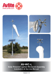
1
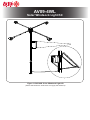
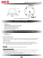
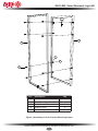
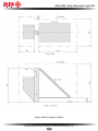
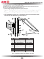
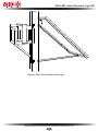
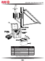
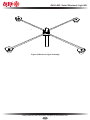
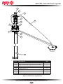
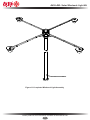
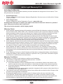
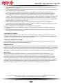
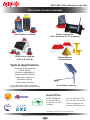
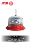
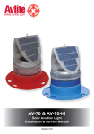
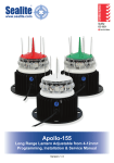
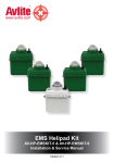
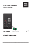
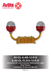
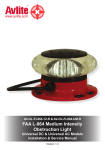
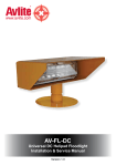
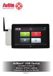
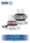
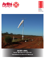
AV09-4WL
Solar Windsock Light Kit
Installation & Service Manual
Version 1.3
AV09-4WL
Solar Windsock Light Kit
Figure 1 AV09-4WL Solar Windsock Light Kit
(Shown with windsock. Avlite does not supply the windsock)
AV09-4WL Solar Windsock Light Kit
Table of Contents
Introduction................................................................................................................... 4
Operating Principle...................................................................................................... 4
Technology.................................................................................................................... 4
AV09-4WL Model........................................................................................................... 5
Optional Configurations.............................................................................................. 5
Assembly & Installation............................................................................................... 6
Assembly of the Solar Panel & Mounting Frame....................................................... 6
Unpacking Instructions......................................................................................................................................6
Initial Inspection.................................................................................................................................................6
Assembly...........................................................................................................................................................6
Installation of the Solar Panel & Battery Box Cage.................................................. 8
Unpacking Instructions......................................................................................................................................8
Initial Inspection.................................................................................................................................................8
Assembly...........................................................................................................................................................8
Installing the Solar Panel & Battery Box Cage................................................................................................10
Installation of the Battery & Battery Box.................................................................. 12
Unpacking Instructions....................................................................................................................................12
Initial Inspection...............................................................................................................................................12
Installing the Battery Box.................................................................................................................................12
Regulator Connection & Operation.......................................................................... 14
Regulator Connection Order...........................................................................................................................14
Selecting Lighting Control Option....................................................................................................................14
Day/Night Transition........................................................................................................................................15
LED Indicators.................................................................................................................................................15
Assembly & Installation of the Solar Windsock Light............................................ 16
Unpacking Instructions....................................................................................................................................16
Initial Inspection...............................................................................................................................................16
Installation.......................................................................................................................................................16
Wiring of Completed Windsock Light Assembly..................................................... 19
Unpacking Instructions....................................................................................................................................19
Initial Inspection...............................................................................................................................................19
Wiring of Windsock Light.................................................................................................................................19
Maintenance & Servicing........................................................................................... 23
Trouble Shooting........................................................................................................ 24
Avlite Light Warranty.................................................................................................. 26
Version No.
Description
Date
Approved
00
01
02
Manual Launch
Installation Details Updated
Note added to Assembly & Installation, washers added
to Fig 5, style of battery change to Fig 7, spring washers
added to Fig 8, appendix added (wiring schematic)
Tech Drawing Update
13 Feb 2005
23 March 2006
15 Aug 2007
C. Procter
C. Procter
C. Procter
27 July 2010
K. Paton
1.3
Latest products and information available at www.avlite.com
3
AV09-4WL Solar Windsock Light Kit
Introduction
Congratulations! By choosing to purchase an Avlite light, you have become the
owner of one of the most advanced solar LED airfield lights in the world.
Avlite Systems draws on more than 25 years experience in the design and manufacture of navigation
aids, and particular care has been taken to ensure your light gives years of trouble free service.
As a commitment to producing the highest quality products for our customers, Avlite has been
independently certified as complying with the requirements of ISO 9001:2000 quality management
system.
By taking a few moments to browse through this booklet, you will become familiar with the versatility of
your light, and be able to maximise its operating function.
Please remember to complete the Avlite warranty registration card accompanying your light.
Operating Principle
The solar module of the light converts sunlight to an electrical current that is used to charge the
battery. The battery provides power to operate the light at night.
The flasher unit has very low current requirements. A microprocessor drives an array of ultra bright
LED’s through a DC/DC converter, which enables the LED’s to operate within the manufacturer’s
specifications. The battery is protected from over-charging within the circuit to ensure maximum
battery life.
On darkness, the microprocessor will initiate a program check and after approximately 1 minute will
turn on.
Technology
Avlite Systems is a world-class solar lighting systems manufacturer with a proven
reputation for rapid, innovative, and agile technology solutions designed specifically
for defense, government, civil and humanitarian aid operations in the most remote,
toughest environments.
Electronics
Avlite employs leading in-house electronic engineers in the design and development of software and
related circuitry. All individual electronic components are sourced directly by Avlite procurement staff
ensuring that only the highest quality components are used in our products.
LED Technology
All aviation lights use the latest advancements in LED (Light Emitting Diode) technology as a light
source. The major advantage of LED’s over traditional light sources is well established in that they
typically have an operational life in excess of 100,000 hours, resulting in substantial savings to
maintenance and servicing costs.
Precision Construction
Commitment to investing in the design and construction of injection-moulded parts including optic
lenses, light bases and a range of other components ensures that all Avlite products are of a
consistent and superior quality.
Optical Performance
Avlite manufactures a range of aviation LED lenses moulded from multi-cavity dies. Complex shapes
such as the AV70 and 16-segment multi-focus lenses are a testament to the company’s superior inhouse lens manufacturing capabilities and outstanding optical performance.
Award-winning, Patented Technology
Several United States and Australian patent registrations are held on Avlite’s range of innovative
designs, with other regional patents pending in Canada, United Kingdom and Europe.
Latest products and information available at www.avlite.com
4
AV09-4WL Solar Windsock Light Kit
AV09-4WL Model
The light source for the AV09-4WL is a high intensity 3watt LED with an appropriate current control
driving circuit. Four lighting arms spaced at 90 degrees apart and facing downwards over the
windsock provide clear illumination of the windsock position.
A master light controller enables activation of the lights once the light level falls to a
predetermined level.
Power to the lights is provided by 2x 55Ah 12volt SLA batteries. This battery is recharged each
day by a 140watt solar module. A 10amp solar regulator is fitted between the solar module and the
battery to ensure the battery is charged correctly and to prevent over charging.
The solar module charging is critical to reliable ongoing operation. It must face the midday sun
and be clear of shadowing by trees or obstructions.
SPECIFICATIONS •
Light Characteristics
Light Source
Available colours
Horizontal & Vertical Divergence
(degrees)
LED Life Expectancy (hours)
4 x domed luminaires each with 1x 3watt ultra-high intensity surface-mounted LED
White
120
Current Draw (mA)
Circuit Protection
Operating Voltage (v)
Temperature Range
1000
Polarity protected
12
-40 to 80°C
Solar Module Type
Output (watts)
Solar Module Efficiency (%)
Charging Regulation
Multicrystalline
140
15
Controller
Battery Type
Battery Capacity (Ah)
Nominal Voltage (v)
Autonomy (nights)
SLA (Sealed Lead Acid)
2 x 55Ah
12
8
CE
Quality Assurance
EN61000-6-3:1997. EN61000-6-1:1997
ISO9001:2000
Trademarks
AVLITE® is a registered trademark of Avlite Systems
Full 3 year warranty
Electrical Characteristics
Solar Characteristics
Power Supply
Certifications
Intellectual Property
Warranty *
>100,000
• Specifications subject to change or variation without notice
* Subject to standard terms and conditions
Optional Configurations
Optional Radio Controlled (AV09-4WL-RF)
The Avlite Solar Windsock Light Kit is also available with Radio Control, whereby lights can be
operated by a wireless handheld controller, which enables personell to remotely activate the lights.
Optional External ON/OFF Switch (AV09-4WL-S)
The Avlite Solar Windsock Light Kit can be fitted with an external ON/OFF switch. The ON/OFF switch
may be useful if the unit is only required for short periods and disconnecting the battery is not viable.
Optional Avlite Pilot Activated Lighting Control
The Avlite Solar Windsock Light Kit can be integrated to a third party Pilot Activated Lighting Controller
(AV-PALC), to allow approaching aircraft to activate lighting on unmanned aerodromes.
Latest products and information available at www.avlite.com
5
AV09-4WL Solar Windsock Light Kit
Figure 2 Leading Dimensions of AV09
Assembly & Installation
The installation of the AV09-4WL Solar Windsock Light includes the following steps:•
•
•
•
•
•
•
Unpacking
Initial Inspection
Assembling the solar panel and mounting frame
Installing the battery box cage and solar panel
Installing the battery with battery box
Assembling and installing windsock lights
Wiring of completed assembly
Assembly of the Solar Panel & Mounting Frame
Tools required
•
•
Adjustable spanner
6mm Allen key
Unpacking Instructions
Unpack all hardware and verify container contents in accordance with Figure 3 “Assembly of Solar
Panel and Mounting Frame”. Please contact your Avlite office if there is any hardware missing.
Initial Inspection
Inspect all hardware for damage. If there is any damage, please contact your Avlite Office.
Note:- If the solar panel and mounting frame have been supplied pre-assembled then proceed to
‘Installation of the Solar Panel & Battery Box Cage’ section of this manual.
Assembly
Refer to Figure 3 “Assembly of Solar Panel and Mounting Frame”.
Assembling the panel & frame
The 120W Solar Panel (Ref 3.1) is attached to the Mounting Frame (Ref 3.2) using bolts (Ref 3.3),
washers (Ref 3.4) and nuts (Ref 3.5).
a. Insert bolts through the holes in the mounting frame, entering from the side of the angle.
b. Fit the Solar Panel flush against the Mounting Frame.
c. Install a washer and a self locking nut on each bolt. Tighten using spanner.
Latest products and information available at www.avlite.com
6
AV09-4WL Solar Windsock Light Kit
1
2
4
5
3
Item
Description
Qty
3.1
140W Solar Panel
1
3.2
Solar Panel Frame
1
3.3
Bolt, 8mm x 20
8
3.4
Washer, 8mm
8
3.5
Self Locking Nut, 8mm
8
Figure 3 Assembly of Solar Panel & Mounting Frame
Latest products and information available at www.avlite.com
7
AV09-4WL Solar Windsock Light Kit
Installation of the Solar Panel & Battery Box Cage
Tools required
•
Digging implement (for post)
•
Under size drill for 12mm screws
•
Spanner
Unpacking Instructions
Unpack all hardware and verify container contents in accordance with Figure 5 “Installation of Solar
Panel & Battery Box Cage”. Please contact your Avlite office if there is any hardware missing.
Initial Inspection
Inspect all hardware for damage. If there is any damage, please contact your Avlite Office.
Installation
Refer to Figure 4 “Panel & Cage Footprint” and Figure 5 “Installation of Solar Panel & Battery Box
Cage” during installation of the panel and cage.
Installing the Post
A suitable mounting point for the Solar Panel and Battery Box Cage is to be provided by the client. It is
usual to use a purpose installed post. The following should be observed:•
The post should be of a durable timber, or other durable material.
•
Recommended minimum post size is 150mm x 150mm, or larger if the Battery Box Cage needs to
be installed immediately beneath the Solar Panel.
•
The length of post required is the sum of exposed length (normally 1.25m) plus the required depth
into the ground which is dependant on local soil conditions (recommended depth 850 minimum).
•
The Solar Panel is to face south if installed in the northern hemisphere and north if in the
Southern hemisphere. Therefore, faces of the post must be aligned with the cardinal points of the
compass.
•
The post should not be more than 20m from the windsock post, and should not be located so as to
place the Solar Panel in shade for a significant time.
•
The Solar Panel is tempered glass, so the post should be located away from any objects which
might fall on the installation.
•
The post and equipment footprint should be at least 300mm clear of the windsock itself under all
conditions.
a. If you are mounting the Panel and Cage on a post, then dig a hole and install the post in the
chosen location.
Latest products and information available at www.avlite.com
8
AV09-4WL Solar Windsock Light Kit
Figure 4 Panel & Cage Footprint
Latest products and information available at www.avlite.com
9
AV09-4WL Solar Windsock Light Kit
Installing the Solar Panel & Battery Box Cage
The Battery Box Cage (Ref 5.2) and the steel support bracket (Ref 5.4) are attached to the post
(Ref 5.3) using coach screws and washers (Ref 5.6, 5.7).
a. Drill the post for the steel support bracket (6 places) and install.
Important: - The Solar Panel is to face south if installed in the northern hemisphere and north if in
the southern hemisphere. Locate the solar panel support bracket accordingly.
b. Drill the post for the Battery Box Cage (6 places) on the opposite side to the solar panel and
install.
c. Install the solar panel and frame (Ref 5.1) and the Brace (Ref 5.5) to the steel support bracket
using bolts (Ref 5.8), washers (Ref 5.9) and nuts (Ref 5.10).
10
9
1
3
2
8
4
6
10
9
5
7
8
6
9
8
10
7
Item
Description
5.1
140W Solar Panel & Frame
Qty
5.2
Battery Box Cage
5.3
Post, 150x150 minimum
5.4
Steel Support
5.5
Steel Brace
5.6
Screw, 12mm x 75
5.7
Washer, 12mm
12
5.8
Bolt, 10mm x 25
4
5.9
Washer, 10mm
4
5.10
Self Locking Nut, 10mm
4
1
1
Client Supplied
1
1
Client Supplied
Figure 5 Installation of Solar Panel & Battery Box Cage
Latest products and information available at www.avlite.com
10
AV09-4WL Solar Windsock Light Kit
Figure 6 Solar Panel & Battery Box Cage
Latest products and information available at www.avlite.com
11
AV09-4WL Solar Windsock Light Kit
Installation of the Battery & Battery Box
Tools required
•
Spanner
Unpacking instructions
Unpack all hardware and verify container contents in accordance with Figure 7 “Battery and Battery
Box”. Please contact your Avlite office if there is any hardware missing.
Initial inspection
Inspect all hardware for damage. If there is any damage, please contact your Avlite Office. Retain
original packing material for possible future use in shipping the AV09-4WL.
Installing the Battery Box
Refer to Figure 7 “Battery and Battery Box” during installation of the Battery and Battery Box.
a. Open the battery box cage door and place the battery case (Ref 7.1) into the cage with the hinge
of the case adjacent to the hinge of the cage.
b. Open the battery case and lower the battery into the case ensuring the battery terminals are
upright.
c. Insert one bolt (Ref 7.3) with a washer (Ref 7.4) under the head through each of the battery
terminals.
d. Connect Battery (-) cable from the solar regulator to the Battery (+) terminal
e. Connect Battery (+) cable from the solar regulator to the Battery (-) terminal
f. Connect Solar (-) cable from the solar regulator to the Solar (-)
g. Connect Solar (+) cable from the solar regulator to the Solar (+)
h. Connect Load (-) cable from the solar regulator to the light (-)
i. Connect Load (-) cable from the solar regulator to the light (+)
Note: The regulator connection points are numbered. Please follow the sequence for correct
installation.
Latest products and information available at www.avlite.com
12
AV09-4WL Solar Windsock Light Kit
Item
Description
7.1
Battery Case, SPC353534
Qty
1
7.2
Battery, 12V 70AH or equivalent
1
7.3
Bolt, battery
2
7.4
Washer, battery
4
7.5
Spring Washer, battery
2
7.6
Nut, battery
2
Figure 7 Battery and Battery Box
Latest products and information available at www.avlite.com
13
AV09-4WL Solar Windsock Light Kit
Regulator Connection & Operation
Regulator Connection Order
The label on the Regulator has each system connection labelled from 1 to 6. This is the recommended
order of system connections.
IMPORTANT: The BATTERY must be connected before the SOLAR to properly start the
microcontroller.
1. BATTERY: Connect the battery (+) and battery (-) to the Regulator
2. SOLAR: First, be certain the battery (+) and battery (-) is connected correctly. Then connect the
solar array to the SOLAR terminals.
Selecting Lighting Control Option
After completing the system connections, select the desired LIGHTING CONTROL option.
A brief description is as follows:
OFF
Lights remain turned off
2, 4, 6, 8, 10
Hours light is turned off after sundown
3/1, 4/2, 6/2
Light is turned on after sundown, turned off during the night, and turned on again
one hour (3/1) or two hours (4/2, 6/2) before sunrise
D/DDusk-to-Dawn, light is on all night
The factory setting of the light is D/D (Dusk-to-Dawn).
To select a lighting option, turn the rotary digital switch to the desired position. An arrow in the rotary
switch will point to the selected position. This is a digital switch, so it will click into each of the ten
positions.
To confirm correct selection of the desired control option, press the TEST button located below the
rotary switches.
LIGHTING CONTROL
LOW VOLTAGE
DISCONNECT
CHARGING
D/D
TEMP SENSE
SOLAR
4
+
BATTERY
3
2
+
LIGHT
1
6
5
+
SEALED
OR
FLOODED
SELECT
OFF
6/2
4
4/2
6
3/1
10
TEST
Regulator Diagram
Latest products and information available at www.avlite.com
14
2
8
AV09-4WL Solar Windsock Light Kit
Day/Night Transition
The Regulator uses the solar array to detect day and night. The transition to night requires the level
of solar radiation being received to be less than 2 percent. The transition back to day requires a high
solar array open-circuit voltage. Both state changes require 10 minutes of continuous transition values
before making change. These constraints avoid false transitions due to lightning or dark storm clouds.
LED Indicators:
Green LED
The green LED indicator will light whenever sunlight is available for battery charging. The green LED
will turn off at night.
Because the Regulator uses a PWM constant voltage charging process, there is usually some amount
of energy going into the battery at all times. Although the charging current falls to very low levels when
the battery reaches full charge, the green LED will continue to stay ON all day. This is to indicate that
the controller is working and that energy is available from the PV array for charging.
Red LED
The red LED is an indicator for 3 different functions:
•
Automatic low voltage load disconnect (LVD)
If the battery charge state falls below the LVD setpoint, the light will be disconnected and the red
LED will light. This indicates the controller has disconnected the load to protect the battery from
further discharge and possible damage. The red LED will turn off when the battery recovers to
about 50% of its rated capacity and the load is automatically reconnected.
•
Initial controller start-up
When the regulator is properly connected to the battery, the red LED will flash 3 times.
•
Confirm lighting control selection
When the TEST button is pressed, the red LED will confirm the lighting control option selected by
the rotary switch.
Latest products and information available at www.avlite.com
15
AV09-4WL Solar Windsock Light Kit
Assembly & Installation of the Solar Windsock Light
Tools required
•
Spanner
Unpacking Instructions
Unpack all hardware and verify container contents in accordance with Figure 8 “Windsock Light Arm &
Mounting Bracket”. Please contact your Avlite Systems office if there is any hardware missing.
Initial Inspection
Inspect all hardware for damage. If there is any damage, please contact your Avlite Systems Office.
Retain original packing material for possible future use in shipping the AV09-4WL.
Installation
Refer to Figure 8 “Windsock Light Arm & Mounting Bracket” during installation of the windsock light.
Assembling the Windsock Light Arms
Windsock Light Arms (Ref 8.2) and AV09 Lights (Ref 8.3) are assembled using bolts (Ref 8.4), spring
washers (Ref 8.5) and plain nuts (Ref 8.6).
a. Insert bolts through the light arm and AV09 from above. Fasten using spring washers and nuts. (4
places). Repeat for four complete light-arm assemblies.
Installing the Windsock Light on the Windsock Post
Light arms are attached to the main windsock post using windsock light mounting brackets (Ref 8.7).
In locating the mounting brackets consider the following:•
The lights are fixed and are not meant to turn with the windsock.
•
Lights should be mounted far enough above the windsock to avoid having the windsock foul on the
lights.
•
The supplied mounting brackets (Ref 8.7) will accommodate a post size from approximately 50mm
to 175mm.
•
Provision is required for the power supply cable (approx 8mm diameter) to run from the power
supply past the wind sock and up to the lights. This is most easily achieved by running the supply
cable down through the middle of the main windsock post and out through a hole near the base.
a. Locate the windsock light mounting brackets on the windsock post and clamp using screwed rods
(Ref 8.8) with washer (Ref 8.9), spring washer (Ref 8.10) and plain nut (Ref 8.11) on each end of
each rod.
b. Fit light-arm assemblies to the mounting brackets using bolts (Ref 8.12), washers (Ref 8.13) and
self locking nuts (Ref 8.14).
Note: The preferred location for windsock lights is above the windsock.
Latest products and information available at www.avlite.com
16
AV09-4WL Solar Windsock Light Kit
7
12
13
2
4
7
13
14
8
1
9
10
11
3
5
6
Item
Description
8.1
Windsock Post
Qty
8.2
Windsock Light Arm
8.3
AV09 Directional LED Area Light
4
8.4
Bolt, 5mm x 20
16
8.5
Spring Washer, 5mm
16
8.6
Plain Nut, 5mm
16
8.7
Windsock Light Mounting Bracket
2
8.8
Screwed Rod, 5/16” x 300mm
4
8.9
Washer, 5/16”
8
8.10
Spring Washer, 5/16”
8
8.11
Plain Nut, 5/16”
8
8.12
Bolt, 8mm x 40
8
8.13
Washer, 8mm
16
8.14
Self Locking Nut, 8mm
8
Client Supplied
4
Figure 8 Windsock Light Arm & Mounting Bracket
Latest products and information available at www.avlite.com
17
AV09-4WL Solar Windsock Light Kit
Figure 9 Windsock Light Assembly
Latest products and information available at www.avlite.com
18
AV09-4WL Solar Windsock Light Kit
Wiring of Completed Windsock Light Assembly
Tools required
•
Spanner
•
Philips head screwdriver
Unpacking Instructions
Unpack all hardware and verify container contents in accordance with Figure 10 “Windsock Light
Wiring”. Please contact your Avlite Systems office if there is any hardware missing.
Initial Inspection
Inspect all hardware for damage. If there is any damage, please contact your Avlite Systems Office.
Retain original packing material for possible future use in shipping the AV09-4WL.
Wiring of Windsock Light
Refer to Figure 10 “Windsock Light Wiring” during installation of windsock light wiring.
The AV09 junction box base (Ref 10.2) has four empty cable glands along its sides which are used for
the AV09 power leads (Ref 10.1). The single cable exiting at the back of the junction box base is the
main power supply lead which is to be routed to the battery box.
a. Route the main power supply lead (coming from the back of the junction box base) down through
the top of the main windsock post, out through the bottom and over to the battery box cage (Figure
6). It is preferable to run the cable through some type of rubber grommet or boot at the top of the
post (client supplied) and it may be necessary to drill an exit hole near the base of the post (also
with a grommet).
b. Feed an AV09 power lead (Ref 10.1) through one of the empty cable glands in the junction box
and join the blue bullet connector to any unused blue connector in the box. Join the red bullet
connector to any unused red connector. Repeat for the remaining three AV09 power leads.
c. Fit the junction box lid (Ref 10.3) to the junction box base using screws (Ref 10.4).
d. Attach the completed junction box to the windsock light mounting bracket using bolts (Ref 10.5),
washers (Ref 10.6) and self locking nuts (Ref 10.7).
Important: Ensure that the junction box lid is faced down.
e. Secure all loose cables using nylon cable ties. Client supplied.
f. Pass the lead through the remaining unused cable gland in the back of the battery case.
g. Connect the main power supply cable ends to the load terminals on the solar regulator.
h. Close battery case lid and engage latches. Close battery box cage door and fasten shut with nut &
bolt or padlock as required (client supplied).
Latest products and information available at www.avlite.com
19
AV09-4WL Solar Windsock Light Kit
5
6
2
3
1
4
6
7
Item
Description
10.1
AV09 Power Lead, (factory fitted)
Qty
4
10.2
AV09 Junction Box, base with mount plate
1
10.3
AV09 Junction Box, lid
1
10.4
Screw, 4mm x 16
4
10.5
Bolt, 6mm x 20
2
10.6
Washer, 6mm
4
10.7
Self Locking Nut, 6mm
2
Figure 10 Windsock Light Wiring
Latest products and information available at www.avlite.com
20
AV09-4WL Solar Windsock Light Kit
Figure 11 Completed Windsock Light Assembly
Latest products and information available at www.avlite.com
21
AV09-4WL Solar Windsock Light Kit
Figure 12 Wiring Schematic
Latest products and information available at www.avlite.com
22
AV09-4WL Solar Windsock Light Kit
Maintenance and Servicing
Designed to be maintenance free, the AV09-4WL requires minimal attention, though the following
maintenance and servicing information is provided to help ensure the life of your Avlite product.
General Maintenance
a. Cleaning Solar PanelsOccasional cleaning of the solar panels may be required. Using a cloth and warm soapy water, wipe
off any foreign matter before rinsing the panels with fresh water.
b. Battery CheckInspection of batteries should be performed every three years (minimum) to ensure that the charger,
battery and ancillary electronics are functioning correctly. Using a voltage meter, check that the
battery voltage is at least 12.3 volts under 500MA load, and ensure all terminals are clear of foreign
matter.
Replacing the Battery
a. Disconnect the load
b. Disconnect the solar
c. Unscrew positive and negative leads and remove battery from the battery box
d. Reattach positive and negative leads to new battery
e. Discard old battery in a safe manner.
f. Reconnect the solar
g. Reconnect the load
h. To test, place dark cover (towel or jacket) on top of light sensor junction box (ref Figure 10) to
activate sensor, light will come on within about 10 seconds.
Follow the instructions for the regulator during assembly. See’Regulator Connection &
Operation’ section of this manual.
Observe the polarity of the battery before the leads are re-connected to ensure the replacement
battery is correctly fitted.
Latest products and information available at www.avlite.com
23
AV09-4WL Solar Windsock Light Kit
Trouble Shooting
Problem
Remedy
Light will not activate.
•
•
•
•
Light will not operate for the
entire night.
• When the lantern is initially removed from storage the battery may be
discharged and require several days of operational conditions to ‘cycle’
up to full autonomy. Expose lantern to direct sunlight and monitor
operation for several days. Avlite products typically require an average
2.5 hours of direct sunlight per day to retain full autonomy.
• Ensure solar module is clean and not covered by shading during the day.
• Do not cover module with protective devices such as a steel cage as
small shadows across cells reduce performance.
• Batteries slowly lose capacity over time. Failure to operate for the full
night may be the result of loss of capacity which means the battery must
be replaced.
Ensure battery connections are correct polarity.
Ensure lantern is in darkness.
Ensure battery terminals are properly connected.
Ensure battery voltage is above 12volts.
Latest products and information available at www.avlite.com
24
AV09-4WL Solar Windsock Light Kit
Notes
Latest products and information available at www.avlite.com
25
AV09-4WL Solar Windsock Light Kit
Avlite Light Warranty V1.0
Activating the Warranty
Upon purchase, the Avlite Systems warranty must be activated for recognition of future claims. To do
this you have two (2) options:
1. Postal Registration
Please complete the Avlite Systems Warranty Registration Card and return to Avlite within 30 days
of your purchase.
2. Online Registration
Please complete the Online Registration Form at; www.avlite.com
Avlite Systems will repair or replace your light in the event of electronic failure for a period of
up to three years from the date of purchase.
The unit must be returned to Avlite freight prepaid.
Warranty Terms
1. Avlite Systems warrants that any Avlite aviation products fitted with telemetry equipment including
but not limited to AIS, GSM, GPS or RF (“Telemetry Products”) will be free from defective materials
and workmanship under normal and intended use, subject to the conditions hereinafter set forth,
for a period of twelve (12) months from the date of purchase by the original purchaser.
2. Avlite Systems warrants that any rotationally-moulded products (“Roto-Moulded Products”) and
accessory products (“Accessory Products”) will be free from defective materials and workmanship
under normal and intended use, subject to the conditions hereinafter set forth, for a period of
twelve (12) months from the date of purchase by the original purchaser.
3. Avlite Systems warrants that any Avlite aviation products other than the Telemetry Products, RotoMoulded Products and Accessory Products (“Avlite Products”) will be free from defective materials
and workmanship under normal and intended use, subject to the conditions hereinafter set forth,
for a period of three (3) years from the date of purchase by the original purchaser.
4. Avlite Systems will repair or replace, at Avlite’s sole discretion, any Telemetry Products, RotoMoulded Products, Accessory Products or Avlite Products found to be defective in material and
workmanship in the relevant warranty period so long as the Warranty Conditions (set out below)
are satisfied.
5. If any Telemetry Products or Avlite Products are fitted with a rechargeable battery, Avlite Systems
warrants the battery will be free from defect for a period of one (1) year when used within original
manufacturer’s specifications and instructions.
Warranty Conditions
This Warranty is subject to the following conditions and limitations;
1. The warranty is applicable to lights manufactured from 1/1/2009.
2. The warranty is void and inapplicable if:
a. the product has been used or handled other than in accordance with the instructions in the
owner’s manual and any other information or instructions provided to the customer by Avlite;
b. the product has been deliberately abused, or misused, damaged by accident or neglect or in
being transported; or
c. the defect is due to the product being repaired or tampered with by anyone other than Avlite or
authorised Avlite repair personnel.
3. The customer must give Avlite Systems notice of any defect with the product within 30 days of the
customer becoming aware of the defect.
4. Rechargeable batteries have a limited number of charge cycles and may eventually need
to be replaced. Typical battery replacement period is 3-4 years. Long term exposure to high
temperatures will shorten the battery life. Batteries used or stored in a manner inconsistent with
the manufacturer’s specifications and instructions shall not be covered by this warranty.
Latest products and information available at www.avlite.com
26
AV09-4WL Solar Windsock Light Kit
5. No modifications to the original specifications determined by Avlite shall be made without written
approval of Avlite Systems.
6. Avlite lights can be fitted with 3rd party power supplies and accessories but are covered by the 3rd
party warranty terms and conditions.
7. The product must be packed and returned to Avlite Systems by the customer at his or her
sole expense. Avlite Systems will pay return freight of its choice. A returned product must be
accompanied by a written description of the defect and a photocopy of the original purchase
receipt. This receipt must clearly list model and serial number, the date of purchase, the name and
address of the purchaser and authorised dealer and the price paid by the purchaser. On receipt
of the product, Avlite Systems will assess the product and advise the customer as to whether the
claimed defect is covered by this warranty.
8. Avlite Systems reserves the right to modify the design of any product without obligation to
purchasers of previously manufactured products and to change the prices or specifications of any
product without notice or obligation to any person.
9. Input voltage shall not exceed those recommended for the product.
10. Warranty does not cover damage caused by the incorrect replacement of battery in solar light
models.
11. This warranty does not cover any damage or defect caused to any product as a result of water
flooding or any other acts of nature.
Limitation of Liability
To the extent permitted by section 68A of the Trade Practices Act 1974 (Cth), the liability of Avlite
Systems under this Warranty will be, at the option of Avlite Systems, limited to either the replacement
or repair of any defective product covered by this Warranty.
Limited to Original Purchaser
This Warranty is for the sole benefit of the original purchaser of the covered product and shall not
extend to any subsequent purchaser of the product.
Miscellaneous
Apart from the specific warranties provided under this warranty, all other express or implied warranties
relating to the above product is hereby excluded to the fullest extent allowable under law. The warranty
does not extend to any lost profits, loss of good will or any indirect, incidental or consequential costs or
damages or losses incurred by the purchaser as a result of any defect with the covered product.
Warrantor
Avlite Systems has authorised distribution in many countries of the world. In each country, the
authorised importing distributor has accepted the responsibility for warranty of products sold by
distributor. Warranty service should normally be obtained from the importing distributor from whom
you purchased your product. In the event of service required beyond the capability of the importer,
Avlite Systems will fulfil the conditions of the warranty. Such product must be returned at the owner’s
expense to the Avlite Systems factory, together with a photocopy of the bill of sale for that product, a
detailed description of the problem, and any information necessary for return shipment.
Information in this manual is subject to change without notice and does not represent a commitment on the part of the vendor.
Avlite products are subject to certain Australian and worldwide patent applications.
Latest products and information available at www.avlite.com
27
AV09-4WL Solar Windsock Light Kit
Other Avlite Products Available
Solar Aviation Lighting
Radio Controlled &
PALC Systems (FCC Compliant)
Obstruction Lighting
(LIOL A & LIOL B)
Airfield Markers
& Accessories
Typical Applications
• Temporary & permanent
airfield lighting
• Remote, emergency &
defence airfield lighting
• Barricade, hazard &
perimeter lighting
• Obstruction Lighting
Area & Sign Lighting
For a complete list of product compliances
including ICAO & FAA, please contact Avlite today
Head Office
Avlite Systems
11 Industrial Drive
Somerville, Vic 3912
Australia
Tel: +61 (0)3 5977 6128
Fax: +61 (0)3 5977 6124
Email: [email protected]
Internet: www.avlite.com
A subsidiary of Sealite Pty Ltd www.sealite.com
Latest products and information available at www.avlite.com
28