1
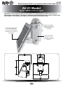
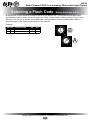
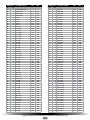
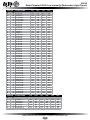
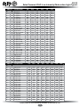
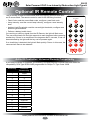
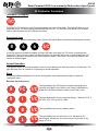
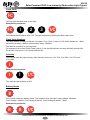
AV-23
Solar Powered ICAO Low Intensity
Obstruction Light Type A
Installation & Service Manual
Version 4.0
AV-23
Solar Powered ICAO Low Intensity Obstruction Light Type A
Table of Contents
Introduction...........................................................................................Page 4
Operating Principle..............................................................................Page 4
Technology............................................................................................Page 4
AV-23 Model..........................................................................................Page 8
Installation of AV-23 Model................................................................Page 10
Selecting an Intensity/ Power Setting..............................................Page 11
Selecting a Flash Code......................................................................Page 12
Flash Codes........................................................................................Page 13
Optional IR Remote Control..............................................................Page 18
Avlite IR Controller / Universal Remote Compatibility....................Page 18
IR Controller Functions......................................................................Page 19
Test Mode / Configure................................................................Page 19
Security Access..........................................................................Page 19
Normal Operation.......................................................................Page 19
Read...........................................................................................Page 19
Flash Code.................................................................................Page 20
Flash Code Numbers.................................................................Page 20
Intensity......................................................................................Page 20
Battery Status.............................................................................Page 20
Lux.............................................................................................Page 21
Error Indication...........................................................................Page 22
Configuration Settings................................................................Page 22
Maintenance and Servicing...............................................................Page 23
Trouble Shooting................................................................................Page 24
Avlite Light Warranty..........................................................................Page 26
Version No.
3.0
4.0
Description
IR Controller Instructions
Remove AV07 Model
Date
Sept 2012
January 2013
Approved
C. Procter
J. Dore
Latest products and information available at www.avlite.com
3
AV-23
Solar Powered ICAO Low Intensity Obstruction Light Type A
Introduction
Congratulations! By choosing to purchase an Avlite light, you have become the owner of
one of the most advanced solar LED airfield lights in the world.
Avlite Systems draws on more than 25 years experience in the design and manufacture of navigation aids,
and particular care has been taken to ensure your light gives years of trouble free service.
As a commitment to producing the highest quality products for our customers, Avlite has been independently
certified as complying with the requirements of ISO 9001:2008 quality management system.
By taking a few moments to browse through this booklet, you will become familiar with the versatility of your
light, and be able to maximise its operating function.
Please remember to complete the Avlite warranty registration card accompanying your light.
Operating Principle
The solar module of the light converts sunlight to an electrical current that is used to charge the battery. The
battery provides power to operate the light at night.
The flasher unit has very low current requirements. A microprocessor drives an ultra bright LED through a
DC/DC converter, which enables the LED to operate within the manufacturer’s specifications. The battery is
protected from over-charging within the circuit to ensure maximum battery life.
On darkness, the microprocessor will initiate a program check and after approximately 1 minute will turn on.
Technology
Avlite Systems is a world-class solar lighting systems manufacturer with a proven
reputation for rapid, innovative, and agile technology solutions designed specifically for
defense, government, civil and humanitarian aid operations in the most remote, toughest
environments.
Electronics
Avlite employs leading in-house electronic engineers in the design and development of software and related
circuitry. All individual electronic components are sourced directly by Avlite procurement staff ensuring that only
the highest quality components are used in our products.
LED Technology
All aviation lights use the latest advancements in LED (Light Emitting Diode) technology as a light source.
The major advantage of LED’s over traditional light sources is well established in that they typically have an
operational life in excess of 100,000 hours, resulting in substantial savings to maintenance and servicing costs.
Precision Construction
Commitment to investing in the design and construction of injection-moulded parts including optic lenses, light
bases and a range of other components ensures that all Avlite products are of a consistent and superior quality.
Optical Performance
Avlite manufactures a range of aviation LED lenses moulded from multi-cavity dies. Complex shapes such
as the AV70 and 16-segment multi-focus lenses are a testament to the company’s superior in-house lens
manufacturing capabilities and outstanding optical performance.
Award-winning, Patented Technology
Several United States and Australian patent registrations are held on Avlite’s range of innovative designs, with
other regional patents pending in Canada, United Kingdom and Europe.
Latest products and information available at www.avlite.com
4
AV-23
Solar Powered ICAO Low Intensity Obstruction Light Type A
AV-23 Model
Solar Obstruction Light
The AV-23 is a low intensity solar powered obstruction light designed to offer users years of
maintenance-free operation. The unit is completely self-contained and incorporates a large 10watt
solar module, 7.5Ah battery, LED light source and advanced driving circuitry.
Interchangeable
LED flasher unit, and
replaceable lens
assembly
Large 10watt adjustable
tilt solar module to
maximise solar radiation
collection for charging
the battery
User-replaceable
battery in large
high-impact resistant
housing
Latest products and information available at www.avlite.com
5
AV-23
Solar Powered ICAO Low Intensity Obstruction Light Type A
SPECIFICATIONS•*
AV-23
Light Characteristics
Light Source
Available colors
Peak Intensity (cd)†
Horizontal Output (degrees)
Vertical Divergence (degrees)
Reflector Type
Available Flash Characteristics
Intensity Adjustments
LED Life Expectancy (hours)
As tested AV-OL-ILA-12-R LED
Red as standard. Other colors available on request, including IR
Complies with ICAO LIOLA
360
+4 to +13
Single LED Optic
>250 including steady-on (user-adjustable)
Adjustable in 25% increments
>100,000
Electrical Characteristics
Current Draw (mA)
Circuit Protection
Nominal Voltage (V)
Temperature Range
Steady-on: 39
Integrated
12
-40 to 80°C
Solar Characteristics
Solar Module Type
Output (watts)
Solar Module Efficiency (%)
Charging Regulation
Multicrystalline
10 (1 x 10watt)
14
Microprocessor controlled
Power Supply
Battery Type
Battery Capacity (Ah)
Nominal Voltage (V)
Battery Service Life
Autonomy (nights)
SLA (Sealed Lead Acid)
7.5
12
Average 5 years
Steady-on: >10
Flashing: >45 (14 hour darkness, 12.5% duty cycle)
Physical Characteristics
Body Material
Lens Material
Lens Diameter (mm/inches)
Lens Design
Mounting
Height (mm/inches)
Width (mm/inches)
Mass (kg/lbs)
Product Life Expectancy
7-stage powder-coated aluminium
LEXAN® Polycarbonate – UV stabilized
107 / 4¼
Single LED Optic
50mm OD pole
365 / 143/8
295 / 115/8
5.5 / 121/8
Up to 12 years
Certifications
CE
Quality Assurance
ICAO
EN61000-6-3:1997. EN61000-6-1:1997
ISO9001:2008
Low Intensity Obstruction Light Type A
Intellectual Property
Trademarks
Warranty *
Options Available
AVLITE® is a registered trademark of Avlite Systems
3 year warranty
• IR Controller
• 200mm bolt pattern mounting plate
• IR LED
• Specifications subject to change or variation without notice
* Subject to standard terms and conditions
† Intensity setting subject to solar availability
Latest products and information available at www.avlite.com
6
AV-23
Solar Powered ICAO Low Intensity Obstruction Light Type A
Installation of AV-23 Model
Charging the Battery
New lights should be connected and left in the sun for 1-2 days to ensure battery is charged
before placing in service.
Preferred Installation Location
For best light performance, ensure solar modules are not covered and are in clear view of the
sky with no shadows.
Light Operation
Light is activated by connecting solar module and battery positive and negative wires. Intensity and
flash settings need to be set prior to activation.
1. Unscrew the two socket cap screws located at either side of the light and remove lens cover.
2. Carefully remove internal flasher unit from within the lens cover.
3. The power and range settings of the light are adjusted by setting the DIP switches located on the
top of this internal flasher unit. Your lantern is normally set to maximum range (see ‘Selecting an
Intensity Setting’ section of this manual).
4. Set rotary switches to the required flash code (see ‘Selecting a Flash Code’ section of this
manual), also located on the top of the internal flasher unit.
5. Replace internal flasher unit back inside light cover.
6. To activate the light, connect the “Battery Negative (-)” wire to the negative terminal, and the
“Battery Positive (+)” wire to the positive terminal of the battery, and the “Solar Negative (-)” wire
to internal “Solar Negative (-)” wire, and the “Solar Positive (+)” wire to the internal “Solar Positive
(+)” wire.
7. Replace lens cover back onto unit, making sure that wires are not protruding, and screw the two
socket cap screws up tight.
8. To test place dark cover (towel or jacket) on top of light to activate sensor, light will come on within
one minute.
Care must be taken to observe the polarity of each wire before they are connected.
To ensure waterproofing of the unit, make sure that no wires are protruding and that there is an
even seal when reattaching the lens cover to the unit body.
Latest products and information available at www.avlite.com
7
AV-23
Solar Powered ICAO Low Intensity Obstruction Light Type A
Selecting an Intensity/Power Setting
Intensity/power settings on Avlite lanterns operate via DIP switches, located near the rotary switches
on the flasher unit. The intensity/power settings may be used to reduce the power consumption and
intensity of the lantern. Setting the lantern to 25% intensity will reduce the power consumption to 25%
of the normal 100% setting and the range by 25%. This setting may be used to adjust the current draw
of the light to local sunlight conditions.
The following diagrams indicate intensity/power settings:-
ON
1
ON
2
100%
1
ON
2
1
75%
ON
2
1
50%
2
25%
Intensity
Setting
Power
mA / hour
100%
100
75%
76
50%
51
25%
26
Power Consumption Calculator
Night Hours
(use 13.7 if
unknown)
Power
mA/hour
X
Model
AV-23
Total power
used per night
(mA)
Duty Cycle
(e.g. 20% = 0.2)
X
Total power
used per night
(mAh)
=
Number of full sunlight hours
required to break even
Solar Panel
Charge (mA)
/
456
(the amount of time it will take for the solar to
replace what the light took out overnight)
=
If the number of Full Sunlight hours is less than 2.5-3.0 hours, please consider reducing the intensity
(Power) or reducing the Duty Cycle.
Latest products and information available at www.avlite.com
8
AV-23
Solar Powered ICAO Low Intensity Obstruction Light Type A
Selecting a Flash Code - Rotary Switches A & B
All lights have 2 rotary switches marked A and B on the flasher unit. Turning the small arrows to the
appropriate number or letter will set the code (see ‘Flash Codes’ section, of this manual). The unit may
take up to one minute to activate a new flash code. A comprehensive list of available flash codes is
listed on pages in the ‘Flash Codes’ section of this manual.
2.7
B
23
789A
F01
Latest products and information available at www.avlite.com
9
BCD
456
0.3
23
FL 3 S
789A
E
OFF
F01
0
ON
E
A
FLASH CODE
BCD
SWITCH
A
B
456
Example:
A
AV-23
Solar Powered ICAO Low Intensity Obstruction Light Type A
Flash Codes
AVLITE® code reference is listed by number of flashes
For the latest version of this document visit www.avlite.com,
or email [email protected]
Symbols
FL
Flash followed by number Eg. FL 1 S, one flash every second
FFixed
Q
Quick flash
VQ
Very quick flash
OC
Occulting; greater period on than off
ISO
Isophase; equal period on and off
LFL Long flash long
MO
Morse code ( ) contains letter
For example, VQ (6) + LFL 10 S means 6 very quick flashes followed by a long flash, during a
10-second interval.
The amount of power your light draws through the night depends on the duty cycle, i.e. the amount of
time on as a proportion to the timing cycle. For example, 0.5 seconds on and 4.5 seconds off equals a
10% duty cycle.
It is best to operate at the lowest duty cycle appropriate to the actual needs of the application.
Please note, Avlite models will retain full autonomy in normal operating conditions with duty-cycles up to
approximately 30%. In applications whereby duty cycles exceed this limit, a reduction in light intensity is
recommended. Please contact a Avlite consultant if assistance is required.
Latest products and information available at www.avlite.com
10
SWITCH
A
B
0
D
E
F
7
8
9
A
8
B
9
C
F
1
0
0
2
3
4
5
6
7
1
8
9
D
1
A
2
B
3
C
D
2
5
E
4
4
5
E
F
6
0
1
2
3
3
F
3
8
4
5
9
6
0
3
3
3
3
3
3
3
4
3
4
3
4
0
5
4
0
0
0
0
0
0
2
0
0
6
5
0
5
0
5
0
0
2
4
2
6
5
5
0
0
5
1
1
1
2
6
2
1
5
1
1
5
1
FLASH CODE
ON
OFF
F (Steady light)
VQ 0.5 S
VQ 0.6 S
VQ 0.6 S
Q1S
Q1S
Q1S
Q1S
Q1S
Q 1.2 S
Q 1.2 S
Q 1.2 S
FL 1.5 S
FL 1.5 S
FL 1.5 S
FL 1.5 S
FL 2 S
FL 2 S
FL 2 S
FL 2 S
FL 2 S
FL 2 S
ISO 2 S
FL 2.5 S
FL 2.5 S
FL 2.5 S
FL 3 S
FL 3 S
FL 3 S
FL 3 S
FL 3 S
FL 3 S
FL 3 S
ISO 3 S
OC 3 S
OC 3 S
OC 3.5 S
FL 4 S
FL 4 S
FL 4 S
FL 4 S
FL 4 S
FL 4 S
FL 4 S
FL 4 S
ISO 4 S
OC 4 S
OC 4 S
FL 4.3 S
FL 5 S
FL 5 S
FL 5 S
FL 5 S
FL 5 S
0.2
0.2
0.3
0.2
0.3
0.4
0.5
0.8
0.3
0.5
0.6
0.2
0.3
0.4
0.5
0.2
0.3
0.4
0.5
0.7
0.8
1.0
0.3
0.5
1.0
0.2
0.3
0.4
0.5
0.6
0.7
1.0
1.5
2.0
2.5
2.5
0.2
0.3
0.4
0.5
0.6
0.8
1.0
1.5
2.0
2.5
3.0
1.3
0.2
0.3
0.5
0.9
1.0
0.3
0.4
0.3
0.8
0.7
0.6
0.5
0.2
0.9
0.7
0.6
1.3
1.2
1.1
1.0
1.8
1.7
1.6
1.5
1.3
1.2
1.0
2.2
2.0
1.5
2.8
2.7
2.6
2.5
2.4
2.3
2.0
1.5
1.0
0.5
1.0
3.8
3.7
3.6
3.5
3.4
3.2
3.0
2.5
2.0
1.5
1.0
3.0
4.8
4.7
4.5
4.1
4.0
SWITCH
A
B
7
4
8
0
1
2
C
B
C
8
9
A
7
B
5
9
6
3
4
A
9
5
D
C
E
B
6
A
6
B
F
C
7
0
1
D
2
E
1
C
D
7
2
8
5
6
F
D
3
0
4
7
A
E
1
2
2
3
3
3
6
5
5
1
1
1
5
1
2
2
4
3
3
4
6
6
5
1
5
4
2
2
6
2
5
4
6
6
6
1
6
1
4
2
2
2
4
6
3
3
1
4
4
2
4
4
6
4
FLASH CODE
ON
OFF
FL 5 S
ISO 5 S
LFL 5 S
OC 5 S
OC 5 S
OC 5 S
FL 6 S
FL 6 S
FL 6 S
FL 6 S
FL 6 S
FL 6 S
FL 6 S
FL 6 S
ISO 6 S
LFL 6 S
OC 6 S
OC 6 S
OC 6 S
FL 7 S
FL 7 S
OC 7 S
FL 7.5 S
FL 7.5 S
FL 8 S
FL 8 S
ISO 8 S
LFL 8 S
OC 8 S
LFL 8 S
FL 9 S
FL 9 S
OC 9 S
FL 10 S
FL 10 S
FL 10 S
FL 10 S
FL 10 S
FL 10 S
LFL 10 S
LFL 10 S
ISO 10 S
LFL 10 S
OC 10 S
OC 10 S
OC 10 S
FL 12 S
FL 12 S
LFL 12 S
FL 15 S
LFL 15 S
OC 15 S
LFL 20 S
FL 26 S
1.5
2.5
2.0
3.0
4.0
4.5
0.2
0.3
0.4
0.5
0.6
1.0
1.2
1.5
3.0
2.0
4.0
4.5
5.0
1.0
2.0
4.5
0.5
0.8
0.5
1.0
4.0
2.0
5.0
3.0
0.9
1.0
6.0
0.2
0.3
0.5
0.8
1.0
1.5
2.0
3.0
5.0
4.0
6.0
7.0
7.5
1.2
2.5
2.0
1.0
4.0
10
2.0
1.0
3.5
2.5
3.0
2.0
1.0
0.5
5.8
5.7
5.6
5.5
5.4
5.0
4.8
4.5
3.0
4.0
2.0
1.5
1.0
6.0
5.0
2.5
7.0
6.7
7.5
7.0
4.0
6.0
3.0
5.0
8.1
8.0
3.0
9.8
9.7
9.5
9.2
9.0
8.5
8.0
7.0
5.0
6.0
4.0
3.0
2.5
10.8
9.5
10.0
14.0
11.0
5.0
18.0
25.0
Latest products and information available at www.avlite.com
11
AV-23
Solar Powered ICAO Low Intensity Obstruction Light Type A
SWITCH
A
B
0
A
E
B
1
A
2
A
3
A
F
9
2
C
4
A
0
7
1
7
9
B
2
9
5
A
7
8
A
A
6
A
7
A
9
9
2
8
3
7
3
9
A
9
7
B
8
A
4
7
8
8
5
7
4
C
5
C
F
B
9
A
9
8
6
7
7
7
6
9
8
7
B
9
9
7
4
9
B
A
C
9
D
9
A
8
A
7
8
B
C
A
D
A
FLASH CODE
ON
OFF
ON
OFF
FL (2) 4 S
VQ (2) 4 S
FL (2) 4.5 S
FL (2) 4.5 S
FL (2) 4.5 S
FL (2) 5 S
FL (2) 5 S
FL (2) 5 S
FL (2) 5 S
FL (2) 5 S
Q (2) 5 S
Q (2) 5 S
FL (2) 5.5 S
FL (2) 6 S
FL (2) 6 S
FL (2) 6 S
FL (2) 6 S
FL (2) 6 S
FL (2) 6 S
FL (2) 6 S
Q (2) 6 S
FL (2) 7 S
FL (2) 8 S
FL (2) 8 S
FL (2) 8 S
FL (2) 8 S
FL (2) 8 S
OC (2) 8 S
OC (2) 8 S
VQ (2) 8 S
FL (2) 10 S
FL (2) 10 S
FL (2) 10 S
FL (2) 10 S
FL (2) 10 S
FL (2) 10 S
FL (2) 10 S
FL (2) 10 S
Q (2) 10 S
FL (2) 12 S
FL (2) 12 S
FL (2) 12 S
FL (2) 15 S
FL (2) 15 S
Q (2) 15 S
FL (2) 20 S
FL (2) 25 S
0.5
0.2
0.3
0.4
0.5
0.2
0.2
0.4
0.5
1.0
0.3
0.5
0.4
0.3
0.3
0.3
0.4
0.5
0.8
1.0
0.3
1.0
0.4
0.4
0.5
0.8
1.0
3.0
5.0
0.2
0.4
0.5
0.5
0.5
0.5
0.8
1.0
1.0
0.6
0.4
0.5
1.5
0.5
1.0
0.2
1.0
1.0
1.0
1.0
1.0
1.0
1.0
0.8
1.2
0.6
1.0
1.0
0.7
0.5
1.4
0.6
0.9
1.0
1.0
1.0
1.2
1.0
0.7
1.0
0.6
1.0
1.0
1.2
1.0
2.0
1.0
1.0
1.6
0.5
1.0
1.5
2.0
1.2
1.0
1.5
0.4
1.0
1.0
2.0
1.5
2.0
0.8
3.0
1.0
0.5
0.2
0.3
0.4
0.5
0.2
0.2
0.4
0.5
1.0
0.3
0.5
0.4
1.0
0.3
0.3
0.4
0.5
0.8
1.0
0.3
1.0
2.0
0.4
0.5
2.4
1.0
1.0
1.0
0.2
0.4
1.5
0.5
0.5
0.5
0.8
1.0
1.0
0.6
0.4
0.5
1.5
2.0
1.0
0.2
1.0
1.0
2.0
2.6
2.9
2.7
2.5
3.8
3.4
3.6
3.0
2.0
3.7
3.5
3.3
4.1
4.5
4.4
4.2
4.0
3.2
3.0
4.7
4.0
5.0
6.2
6.0
3.6
5.0
2.0
1.0
6.6
7.6
7.5
8.0
7.5
7.0
7.2
7.0
6.5
8.4
10.2
10.0
7.0
11.0
11.0
13.8
15.0
22.0
SWITCH
A
B
7
9
5
9
0
C
E
9
3
C
2
B
FLASH CODE
ON
OFF
ON
OFF
ON
OFF
Q (3) 5 S
VQ (3) 5 S
VQ (3) 5 S
VQ (3) 5 S
FL (3) 6 S
FL (2+1) 6 S
0.5
0.2
0.3
0.3
0.5
0.3
0.5
0.3
0.2
0.3
1.0
0.4
0.5
0.2
0.3
0.3
0.5
0.3
0.5
0.3
0.2
0.3
1.0
1.2
0.5
0.2
0.3
0.3
0.5
0.3
2.5
3.8
3.7
3.5
2.5
3.5
Latest products and information available at www.avlite.com
12
AV-23
Solar Powered ICAO Low Intensity Obstruction Light Type A
SWITCH
A
B
A
B
F
A
0
B
B
7
B
8
C
8
C
B
C
7
D
B
D
7
3
8
8
9
B
B
D
8
1
B
E
A
E
7
B
6
4
8
5
8
1
8
F
7
9
D
0
8
F
8
0
9
1
9
6
8
1
C
4
B
3
B
5
B
6
B
SWITCH
A
B
B
F
B
D
8
D
1
D
2
D
F
E
B
E
4
F
C
E
3
D
A
D
4
D
8
E
7
D
D
E
C
D
5
D
0
D
3
F
0
F
E
E
6
F
FLASH CODE
ON
OFF
ON
OFF
ON
OFF
Q (3) 6 S
FL (3) 8 S
FL (3) 9 S
FL (3) 9 S
FL (3) 10 S
FL (3) 10 S
FL (3) 10 S
FL (3) 10 S
FL (3) 10 S
FL (3) 10 S
FL (2+1) 10 S
OC (3) 10 S
Q (3) 10 S
FL (2 + 1) 10 S
FL (3) 12 S
FL (3) 12 S
FL (3) 12 S
FL (3) 12 S
FL (2+1) 12 S
FL (2+1) 12 S
FL (2+1) 13.5 S
FL (3) 15 S
FL (3) 15 S
FL (3) 15 S
FL (2+1) 15 S
FL (2+1) 15 S
FL (2+1) 15 S
FL (2+1) 15 S
VQ (3) 15 S
FL (3) 20 S
FL (3) 20 S
FL (3) 20 S
FL (3) 20 S
0.3
0.5
0.3
0.8
0.3
0.4
0.5
0.5
0.6
1.0
0.5
5.0
0.3
0.5
0.5
0.5
0.8
1.0
0.8
1.0
1.0
0.3
0.4
0.5
0.6
0.7
0.7
1.0
0.1
0.5
0.5
0.8
1.0
0.7
1.0
1.0
1.2
0.7
0.6
0.5
1.5
0.6
1.0
0.7
1.0
0.7
0.5
1.5
2.0
1.2
1.0
1.2
1.0
1.0
1.7
1.0
1.5
0.3
0.5
0.7
2.0
0.5
3.0
1.5
1.2
1.0
0.3
0.5
0.3
0.8
0.3
0.4
0.5
0.5
0.6
1.0
0.5
1.0
0.3
0.5
0.5
0.5
0.8
1.0
0.8
1.0
1.0
0.3
0.4
0.5
0.6
0.7
0.7
1.0
0.1
0.5
0.5
0.8
1.0
0.7
1.0
1.0
1.2
0.7
0.6
0.5
1.5
0.6
1.0
2.1
1.0
0.7
1.5
1.5
2.0
1.2
3.0
2.4
4.0
4.0
1.7
1.0
1.5
0.3
0.5
0.7
5.0
0.5
3.0
1.5
1.2
1.0
0.3
0.5
0.3
0.8
0.9
1.2
0.5
0.5
0.6
1.0
0.5
1.0
0.3
0.5
0.5
0.5
0.8
1.0
0.8
1.0
1.0
0.3
0.4
0.5
1.4
1.9
2.1
1.0
0.1
0.5
0.5
0.8
1.0
3.7
4.5
6.1
4.2
7.1
6.8
7.5
5.5
7.0
5.0
5.7
1.0
7.7
6.5
7.5
6.5
7.2
5.0
6.0
4.0
5.5
10.7
11.8
10.5
11.8
10.7
10.1
5.0
13.7
12.5
15.5
15.2
15.0
FLASH CODE
ON
OFF
ON
OFF
ON
OFF
ON
OFF
VQ (4) 4 S
Q (4) 6 S
Q (4) 6 S
FL (4) 10 S
FL (4) 10 S
Q (4) 10 S
FL (4) 12 S
FL (4) 12 S
FL (4) 12 S
FL (4) 12 S
Q (4) 12 S
FL (4) 15 S
FL (4) 15 S
FL (4) 15 S
FL (4) 16 S
FL (4) 20 S
FL (4) 20 S
FL (4) 20 S
FL (4) 20 S
Q (4) 20 S
Q (4) 28 S
FL (4) 30 S
0.3
0.3
0.4
0.5
0.8
0.3
0.3
0.5
0.5
0.8
0.3
0.5
1.0
1.5
0.5
0.3
0.5
0.5
1.5
0.5
0.5
0.5
0.3
0.7
0.6
1.0
1.2
0.7
1.7
0.5
1.5
1.2
0.7
1.5
1.0
0.5
1.5
3.0
1.5
1.5
1.5
0.5
0.5
0.5
0.3
0.3
0.4
0.5
0.8
0.3
0.3
0.5
0.5
0.8
0.3
0.5
1.0
0.5
0.5
0.3
0.5
0.5
1.5
0.5
0.5
0.5
0.3
0.7
0.6
1.0
1.2
0.7
1.7
0.5
1.5
1.2
0.7
1.5
1.0
0.5
1.5
3.0
1.5
1.5
1.5
0.5
0.5
0.5
0.3
0.3
0.4
0.5
0.8
0.3
0.3
0.5
0.5
0.8
0.3
0.5
1.0
0.5
0.5
0.3
0.5
0.5
1.5
0.5
0.5
0.5
0.3
0.7
0.6
1.0
1.2
0.7
1.7
0.5
1.5
1.2
0.7
1.5
1.0
0.5
1.5
3.0
1.5
4.5
1.5
0.5
0.5
0.5
0.3
0.3
0.4
0.5
0.8
0.3
0.3
0.5
0.5
0.8
0.3
0.5
1.0
0.5
0.5
0.3
0.5
0.5
1.5
0.5
0.5
0.5
2.3
2.7
2.6
5.0
3.2
6.7
5.7
8.5
5.5
5.2
8.7
8.5
8.0
10.5
9.5
9.8
13.5
10.5
9.5
16.5
24.5
26.5
Latest products and information available at www.avlite.com
13
AV-23
Solar Powered ICAO Low Intensity Obstruction Light Type A
SWITCH
A
B
D
D
E
D
E
8
5
F
9
F
9
E
SWITCH
A
B
F
D
A
F
7
F
SWITCH
A
B
6
E
7
E
2
F
2
E
3
E
8
F
SWITCH
A
B
4
E
5
E
1
F
0
E
1
E
FLASH CODE
ON
OFF
ON
OFF
ON
OFF
ON
OFF
ON
OFF
Q (5) 7 S
Q (5) 10 S
FL (5) 16.5 S
FL (5) 20 S
FL (5) 20 S
FL (5) 20 S
0.3
0.3
5.0
0.5
0.8
1.0
0.7
0.7
1.5
0.5
1.2
1.0
0.3
0.3
0.5
0.5
0.8
1.0
0.7
0.7
1.5
0.5
1.2
1.0
0.3
0.3
0.5
0.5
0.8
1.0
0.7
0.7
1.5
0.5
1.2
1.0
0.3
0.3
0.5
0.5
0.8
1.0
0.7
0.7
1.5
0.5
1.2
1.0
0.3
0.3
0.5
0.5
0.8
1.0
2.7
5.7
3.5
15.5
11.2
11.0
FLASH CODE
ON
OFF
ON
OFF
ON
OFF
ON
OFF
ON
OFF
ON
OFF
Q (6) 10 S
FL (6) 15 S
FL (6) 15 S
0.3
0.3
0.5
0.7
0.7
1.0
0.3
0.3
0.5
0.7
0.7
1.0
0.3
0.3
0.5
0.7
0.7
1.0
0.3
0.3
0.5
0.7
0.7
1.0
0.3
0.3
0.5
0.7
0.7
1.0
0.3
0.3
0.5
4.7
9.7
7.0
FLASH CODE
ON
OFF
ON
OFF
ON
OFF
ON
OFF
ON
OFF
ON
OFF
ON
OFF
VQ (6) + LFL 10 S
VQ (6) + LFL 10 S
Q (6) + LFL 15 S
Q (6) + LFL 15 S
Q (6) + LFL 15 S
VQ (6) + LFL 15 S
0.2
0.3
0.2
0.3
0.6
0.3
0.3
0.3
0.8
0.7
0.6
0.3
0.2
0.3
0.2
0.3
0.6
0.3
0.3
0.3
0.8
0.7
0.6
0.3
0.2
0.3
0.2
0.3
0.6
0.3
0.3
0.3
0.8
0.7
0.6
0.3
0.2
0.3
0.2
0.3
0.6
0.3
0.3
0.3
0.8
0.7
0.6
0.3
0.2
0.3
0.2
0.3
0.6
0.3
0.3
0.3
0.8
0.7
0.6
0.3
0.2
0.3
0.2
0.3
0.6
0.3
0.3
0.3
0.8
0.7
0.6
0.3
2.0
2.0
2.0
2.0
2.0
2.0
5.0
4.4
7.0
7.0
5.8
9.4
FLASH CODE
ON
OFF
ON
OFF
ON
OFF
ON
OFF
ON
OFF
ON
OFF
ON
OFF
ON
OFF
ON
OFF
VQ (9) 10 S
VQ (9) 10 S
Q (9) 15 S
Q (9) 15 S
Q (9) 15 S
0.2
0.3
0.2
0.3
0.6
0.3
0.3
0.8
0.7
0.6
0.2
0.3
0.2
0.3
0.6
0.3
0.3
0.8
0.7
0.6
0.2
0.3
0.2
0.3
0.6
0.3
0.3
0.8
0.7
0.6
0.2
0.3
0.2
0.3
0.6
0.3
0.3
0.8
0.7
0.6
0.2
0.3
0.2
0.3
0.6
0.3
0.3
0.8
0.7
0.6
0.2
0.3
0.2
0.3
0.6
0.3
0.3
0.8
0.7
0.6
0.2
0.3
0.2
0.3
0.6
0.3
0.3
0.8
0.7
0.6
0.2
0.3
0.2
0.3
0.6
0.3
0.3
0.8
0.7
0.6
0.2
0.3
0.2
0.3
0.6
5.8
4.9
6.8
6.7
4.8
SWITCH FLASH CODE
ON OFF
A
B
MORSE CODE ( ) INDICATES LETTER
7
8
MO (A) 6 S
0.3
0.6
7
B
MO (A) 8 S
0.4
0.6
8
8
MO (A) 8 S
0.8
1.2
B
8
MO (U) 10 S
0.3
0.7
C
8
MO (U) 10 S
0.4
0.6
D
8
MO (U) 10 S
0.5
0.5
9
8
MO (A) 10 S
0.5
0.5
8
9
MO (D) 10 S
5.0
1.0
A
8
MO (A) 15 S
0.5
1.5
F
8
MO (U) 15 S
0.6
0.3
0
9
MO (U) 15 S
0.7
0.5
1
9
MO (U) 15 S
0.7
0.7
7
D
MO (B) 15 S
1.5
0.5
ON
OFF
1.0
2.0
2.4
0.3
0.4
0.5
1.5
1.0
2.0
0.6
0.7
0.7
0.5
4.1
5.0
3.6
0.7
0.6
0.5
7.5
1.0
11.0
0.3
0.5
0.7
0.5
ON
OFF
0.9
1.2
1.5
7.1
6.8
6.5
1.0
1.0
1.4
1.9
2.1
0.5
11.8
10.7
10.1
0.5
ON
OFF
0.5
10.5
Latest products and information available at www.avlite.com
14
AV-23
Solar Powered ICAO Low Intensity Obstruction Light Type A
Optional IR Remote Control
The IR remote is used to communicate with Avlite lighting products that have
an IR sensor fitted. The remote control is used for the following functions:
Test / Configure
• Flash Code: read the current flash code, configure a new flash code.
• Lamp Intensity: read the current lamp intensity, configure a new intensity
level.
• Ambient Light Thresholds: read the current light thresholds, configure new
ambient light thresholds.
• Perform a battery health check.
On receiving a valid key signal from the IR Remote, the light will flash once.
The user should wait until the light responds to each keypress before pressing
another key. If there is no response to the keypress after 3 seconds, it has not
been detected by the light and the key can be pressed again.
If an invalid key is detected, the light will flash quickly 5 times. In this case, the
command will have to be restarted.
T/C
1
2
3
4
5
6
7
8
9
Read
Lux
R
0
L
Flash Code
Intensity
Battery Status
FC
I
B
Avlite IR Controller / Universal Remote Compatibility
If you lose your Avlite IR Controller, the following Universal Remote Controller has been tested for
compatibility: RCA Type RCR312WR programmed for Phillips TV Type Code 10054
Avlite Key
Universal
Remote Key
T
Power
1
1
2
2
3
3
4
4
5
5
6
6
7
7
8
8
9
9
0
0
R
Channel+
L
Mute
FC
Volume+
I
Volume-
B
ChannelLatest products and information available at www.avlite.com
15
1
1
4
1
4
4
7
7
R
7
R
1RC
C
4C
AV-23
Solar Powered ICAO Low Intensity Obstruction Light Type A
IR Controller Functions
T/C
T/C
2 T/C
3
T/C
2
3
15
3
Security
2 Access26
3 T/C
5
6
48
6
5 T/C
159
26
8
9
1
9
8 T/C
T/C
170
2
3
489L
5
L
0
Normal Operation
0
2R0I T/C
3
4
5
6
1
2
34L
7BL
8
I
B
Read
FC
B
T/C
5
6
7
8
9
1
2
37
4I T/C
5
6
RBI
0
Test Mode / Configure
Pressing the T/C button for upto 5 seconds places the light in Test Mode. The light will flash once in
response to the T/C button being pressed and then turn off. The security code needs to be entered
next to gain access to the IR Controller functions.
Press 8 6 6 T/C. Between each key press, wait for the light to flash once before pressing the next key.
T/C
3
If security access has been accepted, the light will flash once after the T/C button is pressed and
remain off. If an incorrect number has been entered, the light will flash once to acknowledge the T/C
button being pressed, followed by the error sequence flash. If this occurs, the security access code
can be re-entered again.
62
3
5
9
6
8
L
9
0
B
L
3I
B
The light will return to normal operation once it has not detected a valid key press for 30 seconds. The
light will flash once to indicate it is returning to normal operation.
Pressing the Read followed by one of the configuration keys shall cause the light to flash the
configured value.
Example Key Sequences:
1
7
1
2
8
R
4
7
3
2
9
0
5
8
FC
T/C
3R
LI
6
9
4
R
5
4
0
FC
R
7
1
6
5LI
0
8
FC
T/C
2
6
BL
9
The light flashes the current intensity setting: 1 flash for 25%, 2
for 50%, 3 for 75% and 4 for 100%.
7C
8
7I
R
FC
1
4
BI
9
8
0
2
5
T/C
9
BL
The light flashes the current battery status.
T/C
5
2
8
BL
The light flashes the sunset level in Lux, followed by a 2
second gap, followed by the sunrise level. Levels are in the
range of 1 to 9.
R
R
0
FC
4
0LI
1
7
The light flashes the ‘IR Remote’ number belonging to the
currently set Flash Code. Refer to the Flash Code tables to
match the ‘IR Remote’ flash number to the Flash Code.
3
6
6
3
9
Latest products and information available at www.avlite.com
16
1
4
1
7C
4
4
R
Flash Code
7
FC
T/C
R
5
0
8
I
0
2
T/C
FC
3
1I
2B
5
2
6
3
4
5
This key sets the flash code on the light.
Example Key sequence:
Flash Code Numbers
C
3
8
5
9
6
7
9LR
8
4
9
5
6
0
7L
8
9
R
B
0
L
3
FC
I
B
For example if the current Flash Code is set to 51 via the AB switches, the lamp will flash number 081.
For a flash code set to 01, the lamp will flash 001.
T/C
06I
R
2
The flash for number 0 is one long flash.
R5C
7
1
6
The lamp flashes numbers as follows: Hundreds, Tens, Ones. A value of 125 will be flashed as: 1 flash,
followed by a delay, 2 flashes, followed by a delay, 5 flashes.
Intensity
4
0
T/C
3
This sets the flash code to value 123. The light responds by flashing the flash code value.
R2
7
1
8C
6
AV-23
Solar Powered ICAO Low Intensity Obstruction Light Type A
L
9
B
T/C
L
03
8
This function sets the light intensity. Valid intensity values are 1 for 25%, 2 for 50%, 3 for 75% and
4 for 100%.
B
L T/C
FC
I
2 T/C
3
9I
1B T/C
2
1
2
3
5
6
L
1
2
4
5
Battery Status
Example Key sequence:
This sets the light intensity to 25%.
4
8
B
5
9
4
7
6
5
8
0
7
8L
R7
0
B
R
FC
9
0
8
T/C
L
0I
63
6
9
This function reads the battery status. The response from the light is High Voltage: 4 flashes,
Good Voltage: 3 flashes, Low Voltage 2 flashes, Cutoff Voltage or below: 1 flash.
Example Key sequence:
RI
L
9
BL
Latest products and information available at www.avlite.com
17
8
0
I
AV-23
Solar Powered ICAO Low Intensity Obstruction Light Type A
9
Lux
L
This key sets the Ambient Light levels for the light. The format is L <1 (Lux D-N) or 2 (Lux N-D)> <Lux
Level (1 to 9)> T.
B
There are 9 programmable lux levels for both the night - day and day – night transitions. The levels 1
to 9 represent increasing Lux levels. The Lux range between levels 1 and 9 is approximately 50 Lux.
The nominal and factory preset value is 5. This equates to the day - night transition occurring at
around 100Lux, (the level at which the lamp turns on), and a night – day transition of around 150 Lux
(the level at which the lamp turns off).
/C
2
T/C
5
2
8
05
8I
0
I
Day - Night Transition
Night - Day Transition
Level
Lux D-N
(Approx)
Level
Lux N-D
(Approx)
1
60
1
110
2
70
2
120
3
80
3
130
4
90
4
140
5*
100
5*
150
6
110
6
160
7
120
7
170
8
130
8
180
140
9
190
3
6
3
9
9
T/C
T/C T/C
* Factory Preset
Example key sequence:
Assume the current Lux settings are at the factory preset values of 5.
1L6
1
2
1
2
3
2
3
T/C
3
4B9
4
T/C
5
4
5
1
6
5
6
2
6
3
1
7L
7
2
8
7
3
48
9
8
T/C
59
9
6
This sets the ambient light level 2 steps lower than the nominal 100 Lux for the lamp to turn on. This
will make the lamp turn on when its surroundings are darker.
This sets the ambient light level 3 steps higher than the nominal 150 Lux for the lamp to turn off. This
will make the lamp turn off when its’ surroundings are brighter.
R4B
R
5
0
R
0
1
7L6
0
L
2
8L
3
9
7
FC
FC
8I
FC
4I
R
B9
I
B
5
0
B
L6
On successful programming, the light will flash the sunset level (D-N), followed by a 2 second gap,
followed by the sunrise level (N-D).
Latest products and information available at www.avlite.com
18
7
R
C
8
T/C
9
AV-23
Solar Powered ICAO Low Intensity Obstruction Light Type A
Error Indication
If the key sequence is invalid, or an out of bounds value is attempted to be set, the light flashes 5
times for 1 second. (The command then needs to be sent from the start.)
1
0
2L
3
4I
5B
6
T/C
Example key sequence: (Set the intensity level to 5 – undefined.)
Configuration Settings
7
1
8
92
The light flashes 5 times for 1 second.
3
The intensity and flash codes can be changed using the switches on the lamp circuit board or with the
IR Remote Control. The lamp intensity and flash code settings are set to the last detected change,
carried out with the IR Remote Control or by changing the switch positions.
Example #1: If the intensity is set at 100% with the intensity switches, and is then set to 50% using
the IR Remote Control, the intensity setting will change to 50%. If the intensity is then set to 75% using
the switches, the new intensity value will be 75%.
R
L
5
04
6
In order to change intensity settings using the IR Remoter Control, the lamp must be powered.
The lamp can detect a change in switch settings if they are changed while the light is powered down.
FC
7I
B
8
9
R
0
L
Example #2: The flash code is set according to the switch settings: A=5, B = 1. The operator changes
the flash code to 65 (A=4, B=1) using the IR Remote Control. The new flash code is now configured to
A=4, B=1. The lamp is powered down and the operator changes the flash code switches to A=3, B=1
and powers on the light. The new flash code is now A=3, B=1. If the flash code is read from the light
using the IR Remote Control, the lamp will flash 49 which is the corresponding number for switches
A=3, B=1.
Use the IR Remote Control to read the current lamp intensity setting and flash code.
FC
I
B
Latest products and information available at www.avlite.com
19
AV-23
Solar Powered ICAO Low Intensity Obstruction Light Type A
Maintenance and Servicing
Designed to be maintenance free, the AV-23 requires minimal attention, though the following
maintenance and servicing information is provided to help ensure the life of your product.
1. Cleaning Lens- occasional cleaning of the light lens may be required. Using a cloth and warm
soapy water, wipe off any foreign matter before rinsing the lens with fresh water.
2. Battery Check- inspection of batteries should be performed every three years (minimum) to ensure
that the charger, battery and ancillary electronics are functioning correctly. Using a voltage meter,
check that the battery voltage is at least 12 volts under 100MA load, and ensure all terminals are
clear of foreign matter (Battery Connected Units Only).
3. Cleaning Solar Panels (AV-23 Model) - occasional cleaning of the solar panels may be required.
Using a cloth and warm soapy water, wipe off any foreign matter before rinsing the panels with
fresh water.
AV-23 Model Only
Replacing the battery- Don’t throw the unit out!!
The AV-23 light battery compartment provides the user with the ability to change the battery after years
of operation.
1.
2.
3.
4.
5.
6.
Remove the 2 x M8 x 50 SHCS.
Remove battery from AV-23 case and disconnect the battery leads.
Discard old battery in a safe manner.
Reattach positive and negative leads to new battery and then place back into case.
Refit the light head. Tighten SHCS evenly and securely.
To test place dark cover (towel or jacket) on top of light to activate sensor, light will come on.
Care must be taken to observe the polarity of the battery before the leads are re-connected,
and ensure the replacement battery is correctly fitted. Always discard old batteries in a safe
manner.
Long Term Storage Instructions
If the AV-23 is to be placed in storage for an extended period, being more than 5 months, please follow
the below steps.
1. The 12 volt SLA Battery must be stored in a fully charged condition.
2. Remove the light head.
3. Disconnect the battery leads.
All batteries will discharge over time and the rate of discharge is dependent on temperature. If the light
is being stored in temperatures greater than 40°C the battery will discharge faster.
Please check battery every 3-6 months and recharge if necessary.
Recharging the Battery
1. Remove the light head and assembly.
2. Connect the battery leads.
3. Reconnect the battery and place unit in the sun for 2-4 days
Or
Reconnect battery and place in front of a halogen lamp for 2-3 days. (Do not place the halogen light
too close to the solar panel or the panel may be overheated)
Check the battery voltage regularly to make sure the unit is charging correctly.
Latest products and information available at www.avlite.com
20
AV-23
Solar Powered ICAO Low Intensity Obstruction Light Type A
AV-23 Trouble Shooting
Problem
Remedy
Light will not activate.
• Ensure light is in darkness.
• Wait at least 60 seconds for the program to initialise in darkness.
• Ensure switch setting is on a valid code (See Flash Codes section of this
manual).
• Ensure battery terminals are properly connected.
• Ensure battery voltage is above 12.6volts.
Timing codes will not change.
• Turn rotary switches several times to ensure contacts are clear.
Light will not operate for the
entire night.
• Expose light to direct sunlight and monitor operation for several days.
Avlite products typically require 3.0 hours of direct sunlight per day to
retain full autonomy. From a discharged state, the light may require
several days of operational conditions to ‘cycle’ up to full autonomy.
• Reducing the light output intensity or duty cycle (flash code) will reduce
current draw on the battery.
• Ensure solar module is clean and not covered by shading during the day.
Light is constantly on during
the day.
• Ensure the flash code is not set to F F. This flash code is for testing
purposes only and will be steady on for 24 hours a day.
Latest products and information available at www.avlite.com
21
AV-23
Solar Powered ICAO Low Intensity Obstruction Light Type A
Avlite Light Warranty V1.1
Activating the Warranty
Upon purchase, the Avlite Systems warranty must be activated for recognition of future claims. To do
this you have two (2) options:
1. Postal Registration
Please complete the Avlite Systems Warranty Registration Card and return to Avlite within 30 days
of your purchase.
2. Online Registration
Please complete the Online Registration Form at; www.avlite.com
Avlite Systems will repair or replace your lantern in the event of electronic failure for a period
of up to three years from the date of purchase.
The unit must be returned to Avlite freight prepaid.
Warranty Terms
1. Avlite Systems warrants that any Avlite aviation products fitted with telemetry equipment including
but not limited to AIS, GSM, GPS or RF (“Telemetry Products”) will be free from defective materials
and workmanship under normal and intended use, subject to the conditions hereinafter set forth,
for a period of twelve (12) months from the date of purchase by the original purchaser.
2. Avlite Systems warrants that any rotationally-moulded products (“Roto-Moulded Products”) and
accessory products (“Accessory Products”) will be free from defective materials and workmanship
under normal and intended use, subject to the conditions hereinafter set forth, for a period of
twelve (12) months from the date of purchase by the original purchaser.
3. Avlite Systems warrants that any Avlite aviation products other than the Telemetry Products, RotoMoulded Products and Accessory Products (“Avlite Products”) will be free from defective materials
and workmanship under normal and intended use, subject to the conditions hereinafter set forth,
for a period of three (3) years from the date of purchase by the original purchaser.
4. Avlite Systems will repair or replace, at Avlite’s sole discretion, any Telemetry Products, RotoMoulded Products, Accessory Products or Avlite Products found to be defective in material and
workmanship in the relevant warranty period so long as the Warranty Conditions (set out below)
are satisfied.
5. If any Telemetry Products or Avlite Products are fitted with a rechargeable battery, Avlite Systems
warrants the battery will be free from defect for a period of one (1) year when used within original
manufacturer’s specifications and instructions.
Warranty Conditions
This Warranty is subject to the following conditions and limitations;
1. The warranty is applicable to lanterns manufactured from 1/1/2009.
2. The warranty is void and inapplicable if:
a. the product has been used or handled other than in accordance with the instructions in the
owner’s manual and any other information or instructions provided to the customer by Avlite;
b. the product has been deliberately abused, or misused, damaged by accident or neglect or in
being transported; or
c. the defect is due to the product being repaired or tampered with by anyone other than Avlite or
authorised Avlite repair personnel.
3. The customer must give Avlite Systems notice of any defect with the product within 30 days of the
customer becoming aware of the defect.
4. Rechargeable batteries have a limited number of charge cycles and may eventually need
to be replaced. Typical battery replacement period is 3-4 years. Long term exposure to high
temperatures will shorten the battery life. Batteries used or stored in a manner inconsistent with
the manufacturer’s specifications and instructions shall not be covered by this warranty.
Latest products and information available at www.avlite.com
22
AV-23
Solar Powered ICAO Low Intensity Obstruction Light Type A
5. No modifications to the original specifications determined by Avlite shall be made without written
approval of Avlite Systems.
6. Avlite lights can be fitted with 3rd party power supplies and accessories but are covered by the 3rd
party warranty terms and conditions.
7. The product must be packed and returned to Avlite Systems by the customer at his or her
sole expense. Avlite Systems will pay return freight of its choice. A returned product must be
accompanied by a written description of the defect and a photocopy of the original purchase
receipt. This receipt must clearly list model and serial number, the date of purchase, the name and
address of the purchaser and authorised dealer and the price paid by the purchaser. On receipt
of the product, Avlite Systems will assess the product and advise the customer as to whether the
claimed defect is covered by this warranty.
8. Avlite Systems reserves the right to modify the design of any product without obligation to
purchasers of previously manufactured products and to change the prices or specifications of any
product without notice or obligation to any person.
9. Input voltage shall not exceed those recommended for the product.
10. Warranty does not cover damage caused by the incorrect replacement of battery in solar lantern
models.
11. This warranty does not cover any damage or defect caused to any product as a result of water
flooding or any other acts of nature.
12. There are no representations or warranties of any kind by Avlite or any other person who is an
agent, employee, or other representative or affiliate of Avlite, express or implied, with respect to
condition of performance of any product, their merchantability, or fitness for a particular purpose, or
with respect to any other matter relating to any products.
Limitation of Liability
To the extent permitted by section 68A of the Trade Practices Act 1974 (Cth), the liability of Avlite
Systems under this Warranty will be, at the option of Avlite Systems, limited to either the replacement
or repair of any defective product covered by this Warranty. Avlite Systems will not be liable to Buyer
for consequential damages resulting from any defect or deficiencies in accepted items.
Limited to Original Purchaser
This Warranty is for the sole benefit of the original purchaser of the covered product and shall not
extend to any subsequent purchaser of the product.
Miscellaneous
Apart from the specific warranties provided under this warranty, all other express or implied warranties
relating to the above product is hereby excluded to the fullest extent allowable under law. The warranty
does not extend to any lost profits, loss of good will or any indirect, incidental or consequential costs or
damages or losses incurred by the purchaser as a result of any defect with the covered product.
Warrantor
Avlite Systems has authorised distribution in many countries of the world. In each country, the
authorised importing distributor has accepted the responsibility for warranty of products sold by
distributor. Warranty service should normally be obtained from the importing distributor from whom
you purchased your product. In the event of service required beyond the capability of the importer,
Avlite Systems will fulfil the conditions of the warranty. Such product must be returned at the owner’s
expense to the Avlite Systems factory, together with a photocopy of the bill of sale for that product, a
detailed description of the problem, and any information necessary for return shipment.
Information in this manual is subject to change without notice and does not represent a commitment on the part of the vendor.
Sealite products are subject to certain Australian and worldwide patent applications.
Latest products and information available at www.avlite.com
23
AV-23
Solar Powered ICAO Low Intensity Obstruction Light Type A
Other Avlite Products Available
Solar Aviation Lighting
Radio Controlled &
PALC Systems (FCC Compliant)
Obstruction Lighting
(LIOL A & LIOL B)
Airfield Markers
& Accessories
Typical Applications
• Temporary & permanent
airfield lighting
• Remote, emergency &
defence airfield lighting
• Barricade, hazard &
perimeter lighting
• Obstruction Lighting
Area & Sign Lighting
For a complete list of product compliances
including ICAO & FAA, please contact Avlite today
Head Office
Avlite Systems
11 Industrial Drive
Somerville, Vic 3912
Australia
Tel: +61 (0)3 5977 6128
Fax: +61 (0)3 5977 6124
Email: [email protected]
Internet: www.avlite.com
A subsidiary of Sealite Pty Ltd www.sealite.com
Latest products and information available at www.avlite.com
24


![Installation Manual [PDF 4.6 MB]](http://vs1.manualzilla.com/store/data/006008736_1-137b4e33f3bd3f098e11b56c54272240-150x150.png)