1
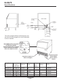
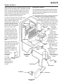
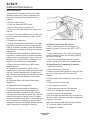
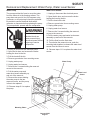
SCE275
Introduction
To the owner or user: This service manual is
intended to provide you, and the maintenance or
service technician, with the information needed to
install, start up, clean, maintain and repair this
product.
The SCE275 is an ice machine that produces
cubed ice on a vertical freezing surface. The cubes
fall into the ice storage bin where they break up
into individual cubes.
The SCE275 automatically maintains the level of
ice by turning on when the ice level falls, and
switches off when the bin is full.
This unit is serviceable in place; the ice storage bin
and hood may be removed from the chassis to
allow service access without removing the ice
machine from its installed position. The
refrigeration system uses R-404A as the
refrigerant.
Table of Contents
Specifications · · · · · · · · · · · · · · · · · · · · · · · · · · · · · · · · · · · · · · · · · · · 2
For The Installer: Environmental Limitations · · · · · · · · · · · · · · · · · · · · · · · · · · · 3
Installation · · · · · · · · · · · · · · · · · · · · · · · · · · · · · · · · · · · · · · · · · · · · · 4
Installation · · · · · · · · · · · · · · · · · · · · · · · · · · · · · · · · · · · · · · · · · · · · · 5
For The Plumber· · · · · · · · · · · · · · · · · · · · · · · · · · · · · · · · · · · · · · · · · · 6
Installation · · · · · · · · · · · · · · · · · · · · · · · · · · · · · · · · · · · · · · · · · · · · · 7
Removal of the Cabinet · · · · · · · · · · · · · · · · · · · · · · · · · · · · · · · · · · · · · · 8
Component Location · · · · · · · · · · · · · · · · · · · · · · · · · · · · · · · · · · · · · · · 9
Component Description · · · · · · · · · · · · · · · · · · · · · · · · · · · · · · · · · · · · · · 10
AutoIQ Controller · · · · · · · · · · · · · · · · · · · · · · · · · · · · · · · · · · · · · · · · · 11
Initial Start Up · · · · · · · · · · · · · · · · · · · · · · · · · · · · · · · · · · · · · · · · · · · 12
Notes On Operation · · · · · · · · · · · · · · · · · · · · · · · · · · · · · · · · · · · · · · · · 13
Adjustments · · · · · · · · · · · · · · · · · · · · · · · · · · · · · · · · · · · · · · · · · · · · 14
How To Operate The AutoIQ Controller · · · · · · · · · · · · · · · · · · · · · · · · · · · · · · 15
How The Electronic Cuber Works · · · · · · · · · · · · · · · · · · · · · · · · · · · · · · · · · 16
Water System · · · · · · · · · · · · · · · · · · · · · · · · · · · · · · · · · · · · · · · · · · · 17
Technicians Only: Freeze Cycle Operational Sequence · · · · · · · · · · · · · · · · · · · · · 18
Technicians Only: Harvest Cycle Operational Sequence · · · · · · · · · · · · · · · · · · · · · 19
Sanitizing and Water System Cleaning · · · · · · · · · · · · · · · · · · · · · · · · · · · · · · 20
Sanitizing and Cleaning · · · · · · · · · · · · · · · · · · · · · · · · · · · · · · · · · · · · · · 21
Additional Maintenance · · · · · · · · · · · · · · · · · · · · · · · · · · · · · · · · · · · · · · 22
Additional Maintenance · · · · · · · · · · · · · · · · · · · · · · · · · · · · · · · · · · · · · · 23
Additional Maintenance: Bin Controls · · · · · · · · · · · · · · · · · · · · · · · · · · · · · · · 24
Technical Characteristics · · · · · · · · · · · · · · · · · · · · · · · · · · · · · · · · · · · · · 25
Service Diagnosis · · · · · · · · · · · · · · · · · · · · · · · · · · · · · · · · · · · · · · · · · 26
Service Diagnosis · · · · · · · · · · · · · · · · · · · · · · · · · · · · · · · · · · · · · · · · · 27
Service Diagnosis · · · · · · · · · · · · · · · · · · · · · · · · · · · · · · · · · · · · · · · · · 28
PTCR · · · · · · · · · · · · · · · · · · · · · · · · · · · · · · · · · · · · · · · · · · · · · · · 29
Removal and Replacement: AutoIQ Controller · · · · · · · · · · · · · · · · · · · · · · · · · · 30
Removal and Replacement: Water Pump, Water Level Sensor · · · · · · · · · · · · · · · · · · 31
Removal and Replacement: Inlet Valve & Water Trough · · · · · · · · · · · · · · · · · · · · · 32
Removal and Replacement: Bin Control Set · · · · · · · · · · · · · · · · · · · · · · · · · · · 33
Removal and Replacement: Thermistors · · · · · · · · · · · · · · · · · · · · · · · · · · · · · 34
Water Distributors · · · · · · · · · · · · · · · · · · · · · · · · · · · · · · · · · · · · · · · · · 35
Refrigeration System Service: R-404A · · · · · · · · · · · · · · · · · · · · · · · · · · · · · · 36
Parts lists and wiring diagrams are located in
This manual was printed on recycled paper.
the center of this manual.
January 2003
Page 1
SCE275
Specifications
WATER REGULATOR
3/8-18 NPT
(W/C ONLY)
4.00 IN.
10.16 CM.
MINIMUM UTILITY
CLEARANCE
BACK VIEW
POTABLE
WATER INLET
3/8 FLARE
3.68 IN.
9.35 CM.
4.59 IN.
11.66 CM.
4.06 IN.
10.31 CM.
6.00 IN
15.2 CM.
3/4 FPT
DRAIN
1.68 IN.
4.27 CM.
ELECTRICAL CORD
7.17 IN.
18.21 CM.
COND DRAIN
1/2-13 NPT
(W/C ONLY)
9.12 IN.
23.16 CM.
The unit is equipped with an electrical power cord,
but should only be plugged into a circuit dedicated
to the ice machine.
11.35 IN.
28.83 CM.
THE NAMEPLATE IS LOCATED
ON THE BACK PANEL
A Serial Number Plate is Located
on the Front Edge of the Base,
Behind the Right Front Grill
AutoIQ Controller
(Behind Right
Grill in A thru F
Series)
Controller Location in G
Series and Higher
Model Number Dimensions
Basic
(w/o) legs
Electrical
H" x W" x D"
SCE275A-1G 33 x 30 14 x 30 115/60/1
Condenser Total
Type
Load
Amps
Air
15
Total Unit
Wattage
Refrigerant R-404A
(HP62)
18 ounces
SCE275A-32G 33 x 30¼ x 30 208-230/60/1 Air
8.4
18 ounces
SCE275W-1G 33 x 30 14 x 30
115/60/1
Water
15
12 ounces
SCE275A-6G
33 x 30 14 x 30
230/50/1
Air
7.5
1725
18 ounces
SCE275W-6G 33 x 30 x 30
230/50/1
Water
7.5
1725
12 ounces
1
4
January 2003
Page 2
SCE275
For The Installer: Environmental Limitations
The ice machine must be installed indoors in a
controlled environment.
Min
Max
Air Temp
0
50 F.
1000F.
Water Temp
400F.
1000F.
Water Pressure
20 PSI
80 PSI
Voltage (60 Hz)
103.5
126.5
Voltage (50 Hz)
207
253
Air In
Air Out
Operating the ice machine outside of the above
limitations, or outdoors, is potentially damaging to
the machine, and it is misuse of the machine. This
may void the warranty.
Scotsman Ice Systems are designed and
manufactured with the highest regard for safety
and performance. They meet or exceed the
standards of UL, NSF, and CUL
Scotsman assumes no liability or responsibility of
any kind for products manufactured by Scotsman
that have been altered in any way, including the
use of any part and/or other components not
specifically approved by Scotsman.
Airflow on air cooled models is:
Intake through the left front grill.
Exhaust through the right front grill.
Do not install where this air flow is obstructed.
The SCE275 has a removable cabinet. When
installed, the machine should have some extra
clearance ( 18") on the left and right sides so that the
cabinet may be easily removed when the machine
is in place.
Scotsman reserves the right to make design
changes and/or improvements at any time.
Specifications and design are subject to change
without notice.
January 2003
Page 3
SCE275
Installation
Water
The water supply for this ice machine has been in
contact with many materials since it fell from the
sky as rain. All rain is slightly acidic, and tends to
dissolve the materials it comes in contact with.
During water’s journey to the ice machine, it has
flowed over and through the ground, been picked
up by a municipal or private pump, forced through
a series of pipes of differing construction and may
have been treated by the municipality providing the
water.
Electrical power is supplied through a cord
connected to the unit. All local codes must be
followed.
This means that there is no such thing as “pure”
water. All water contains some level of impurity.
There are two ways water carries the impurities:
suspended and dissolved. Water filters can remove
the suspended solids, but cannot remove the
dissolved portion.
and electrical power supply.
No extension cords are allowed. The building drain
inlet must be lower than the drain outlet(s) at the
back of the ice machine. The water supply must
have a hand shut off valve accessible when the
unit is installed.
Cube ice machines use more water than is made
into ice, the excess amount is used to dilute the
concentration of minerals and “rinse” out the water
system to keep the water scale from clogging up
the machine. That water rinse, combined with
water filters, prolongs the times between needed
water system cleanings.
2. Determine the method of installation, is the
machine to be installed under the counter? Is the
drain in the floor under the machine? Is the water
inlet valve accessible?
The water to the ice machine should be filtered.
Water filters vary greatly in ability and function.
Install one that filters out suspended solids to a
dimension of 5 microns or less. The finer the filter
the better, but finer filters may plug-up sooner than
course ones. It may be necessary to add a course
filter ahead of the fine filter to prolong filter life.
Pre-installation:
1. Inspect the place where the ice machine is to be
installed. Check for:
space for the cabinet,
water supply,
drain availability
Unpack and Assemble
1. Remove legs and scoop from storage bin.
2. Remove shipping materials from ice making
area.
The SCE275 is factory set for a water purge that
will work in most water conditions. While the
amount of purge is adjustable, only change it if
necessary.
Note: Water use adjustments are customer
convenience adjustments; they are not factory
defects and are NOT covered by warranty.
This ice machine may be installed in the open or
under a counter. No clearance is required at the
sides or top beyond what’s needed to place the
cabinet into position. Air cooled models blow air in
and out through the grills at the front. Space is
required for utility connections at the back.
The ice machine is not designed for outdoor
use. It must be installed indoors, in a controlled
environment. The air and water temperatures
must not exceed rated limits.
Remove Material Located Between
Cube Deflector and Troughs
3. Place corner posts from the shipping carton on
the floor behind the ice machine. Tip the ice
machine on its back and remove the shipping skid.
4. Screw the legs into the threaded holes in the
base of the ice machine.
5. Tip the ice machine back to an upright position.
January 2003
Page 4
SCE275
Installation
For The Plumber
Begin by planning the installation and obtaining the
needed supplies:
3
3
3
" soft copper tubing
8
" rigid drain tubing
4
" FPT fitting for bin/reservoir drain connection
4
" FPT fitting for condenser drain connection
1
2
" FPT fitting for water cooled condenser inlet
connection
1. Connect cold potable water to the 3 8" male flare
at the back of the cabinet. A water filter and hand
shut off valve is recommended. Flush the water
line prior to connecting to the ice machine.
3
8
If water cooled, connect a separate water inlet line
to the water cooled condenser inlet fitting. It should
also have a hand shut off valve.
A loop of copper tubing may be used between the
ice machine and the water supply. This will allow
the ice machine to be pulled out from its installed
location without disconnecting the water line. No
back-flow preventer should be needed in the inlet
potable water line because provision for that is
incorporated in this N.S.F. listed product (the water
valve outlet is above the reservoir wall and cannot
siphon).
2. Connect a drain tube to each drain connection
(water cooled drain must be separate).
3. Route the drain tubes to the building drain
receptacle.
CONFORM TO ALL LOCAL CODES
Plumbing Connections,
Water Cooled Shown
Reservoir & Bin
Drain
Field Supplied Filter
and Hand Valve
Water Cooled Inlet
Potable Water Inlet
Water Cooled Drain
Drain Receptacle
January 2003
Page 5
SCE275
For The Plumber
Drain Configuration:
Water cooled models must use a separate drain
tube from the reservoir/bin drain.
The water cooled condenser drain should not be
vented.
Drain tube material must be rigid and meet local
code.
Traps in the bin drain line without vents ahead of
them will cause poor draining.
The bin drain must be vented if there is a long
horizontal run (5’ or more).
All drains are gravity, and must have a minimum
fall of ¼" per foot of horizontal run.
Maintain the air gap required by local code
between the end of the drain tubes and the
building drain
receptacle.
Note: Drain tubing
should be insulated
to prevent
condensation from
forming on the
tubing.
Vented Drain
Potable Water
Supply
Air Cooled Plumbing
Connections
January 2003
Page 6
SCE275
Installation
For The Electrician
The 115 volt, 60 Hz model is a cord-connected
unit, and must be on a separate 115 volt AC 60
cycle single phase power supply. The maximum
fuse size for this circuit should be 15 amps. Per the
nameplate use fuses, or HACR circuit breakers.
Connect 50 Hz models to the correct voltage and
fuses.
Follow All Local Codes - This Unit Must Be
Grounded. Do not use extension cords and do not
disable or by-pass ground prong on electrical plug.
After Utility Connections:
1. Level the cabinet, use the leg levelers on the
end of the legs to adjust the cabinet height. (Legs
should have been installed when the unit was
unpacked). Check for levelness at the reservoir.
2. Wash out the bin and hood. If desired, the
interior of the bin could be sanitized.
3. Locate the scoop, wash it and have it available
for use when needed.
Final Check List
1. Is the ice maker cabinet in a room where
ambient temperatures are within the minimum and
maximum temperatures specified?
2. Has the water supply been connected?
3. Is the water pressure adequate?
4. Have the water connections been checked for
water leaks?
5. Have the drain connections been made?
6. Have the drain connections been checked for
leaks?
7. Is the cabinet level?
10. Has the bin and cabinet been wiped clean and
sanitized?
11. Has the Customer Evaluation & Warranty
Registration form been filled out? Check for correct
model and serial numbers from the nameplate,
then mail the completed form to Scotsman.
12. Has the owner/user been given the name and
telephone number of the authorized Scotsman
Service Agency serving that location?
13. To start up machine, follow the directions on
page 12. For more information on the unit, turn to
the next page.
8. Is the ice machine plugged into an electrical
power supply of the proper voltage and is the ice
machine the only load on that circuit?
9. Has all of the shipping material been removed
from the inside of the cabinet? Check for
materials between the cube deflector and the
water troughs (see page 4). Be sure the cube
deflector is in place.
January 2003
Page 7
SCE275
Removal of the Cabinet
One of the most useful features of this ice machine
is the ability to remove the cabinet from the ice
machine without removing the ice machine from its
installed position.
4. Pull the hood and door assembly straight out
until it can be lifted up.
STEP 4
Hood
To Remove:
To remove the cabinet base the hood must be
removed first.
1. Remove 5 screws and the three grills at the front
of the base.
STEP 1
5. In the area behind the grills (removed in step 1)
are two knobs similar to those removed in step 3.
2. Push and hold the Off button the AutoIQ
Controller until the machine has switched OFF. Be
certain the ice machine has been switched off.
STEP 5
STEP 2
Unscrew and remove the two knobs.
6. Locate the bin drain. Loosen the hose clamp
holding the drain tube to its fitting and pull the drain
tube off of the fitting.
Note: Controller on left
side of cabinet on G
series and higher.
7. Lift up the front of the base and rotate the base
up and off of the ice machine.
3. Open the bin door and unscrew the knobs at the
left and right inside of the ice storage bin. Unscrew
the knobs all the way out.
STEP 3
Bin Drain
The machine is now exposed for service.
January 2003
Page 8
SCE275
Component Location
The ice machine is designed for front service.
Many components are serviceable from the front
without removing the cabinet. With the cabinet
removed, nearly all components are serviceable.
When the bin is removed, the condensing unit is
visible.
Water Distributors
Evaporator Cover
Reservoir
Evaporators
Water Trough
Cube Deflector
Compressor
Refrigeration
Access Valves
Water Inlet
Valve
AutoIQ
Controller,
location shown
for A thru F
series
Fan Motors
Component Location
These parts are located inside the bin:
Evaporators
Water Reservoir
Water Pump
Cube Deflector
Water Troughs
Water Distributors
Controller Location, G series
and higher
Water Level Sensor
January 2003
Page 9
SCE275
Component Description
High Pressure Cut Out - Water Cooled Only
Evaporators/Freezing Compartment:
This is a switch that opens to stop the ice machine
when the internal refrigeration pressures become
too high (over 450 PSIG). It is an automatic reset.
Location of the 2 evaporators. Ice forms on the
evaporators and is released when warmed up
during the harvest cycle.
Evaporators
Cube Deflector:
Where the ice is formed. There are two vertical
evaporator plates that form vertical strips of cubes.
The strips break up into individual cubes as they
fall.
The slots in the inclined deflector let the water
falling from the evaporators back into the reservoir,
but when ice falls during harvest, the ice slides off
into the bin.
Thermostatic Expansion Valve
Water Trough
The thermostatic expansion valve is used to meter
liquid refrigerant into the evaporator, adjusting the
flow of refrigerant as required to make ice.
Diverts water from the evaporators to the right and
left to keep water off the ice.
Reservoir:
Only to be used by a certified technician. Allows
access to the refrigeration system for diagnostic
information.
Contains the water used for ice.
Water Inlet Valve:
Refrigeration Service Access Valves:
Opens to allow water into the reservoir.
Water Pump:
Water Level Sensor:
Forces the water from the reservoir to the top of
the evaporators. The motor is separated from the
reservoir water to minimize contact with the water.
Controls the size of the ice cube by measuring how
much water is used in a cycle. It consists of a float,
stem and electric eye. The stem will move slightly
when the pump is on, this is normal. As the
machine makes ice the reservoir water level will fall
and the visible portion of the stem will slide down
thru the slot in the sensor body.
AutoIQ Controller:
Controls the operation of the ice machine. Turns it
on and off; switches it between cycles; shows
information via indicator lights; and shuts the
machine down if there is a problem.
Compressor:
The refrigerant vapor pump, it forces the refrigerant
to flow thru the refrigeration system tubing.
Hot Gas Valve:
Closed during freeze, it opens during harvest to
divert hot discharge refrigerant gas into the inlet of
the evaporators.
Condenser:
Either air or water cooled, discharges the heat
produced in ice making.
January 2003
Page 10
SCE275
AutoIQ Controller
Indicator Lights:
Cycle Definitions:
Bin Full: On when bin is full, goes on and off as
ice falls during a harvest cycle.
Freeze: On when the unit is in the Freeze cycle,
blinks when a freeze mode is pending.
Freeze: The refrigeration system is operating to
remove heat from the evaporators. The
compressor, fan motor (if air cooled) and water
pump are ON.
Harvest: The refrigeration and water systems
are operating to harvest the ice cubes. While
the compressor is on for the full cycle, the water
pump will be off at the beginning and inlet water
valve will switch off before the end.
Harvest: On when the unit is in the Harvest
cycle.
Clean: On when the unit is in the Clean cycle,
blinks when preparing for a clean mode.
Off: On when the unit has been switched off,
blinks when the machine is preparing to shut off.
Water Error: On when the controller has
identified a problem with the water system.
Clean: The Inlet Water Valve opens to fill the
reservoir. The Water Pump starts. The Clean
indicator light is switched ON. A manually
initiated rinse flushes the system.
Refrigeration Error: On when the controller
has identified a problem with the refrigeration
system.
8
9
7
PUSH BUTTON
CONTROL SWITCHES
6
5
INDICATOR LIGHTS:
BIN FULL
4
FREEZE
3
HARVEST
CLEAN
2
OFF
ERROR LIGHTS:
WATER
1
REFRIGERATION
January 2003
Page 11
SCE275
Initial Start Up
1. Remove two screws and the left grill (G series
and higher).
2. Locate the AutoIQ Controller - use a flashlight to
see the buttons and lights.
3. Plug the machine in or switch on the electrical
power. Note that the controller’s indicator lights all
flash on briefly when power is connected.
The freeze cycle will continue until the water
level in the reservoir has fallen again to its
factory set point, then the AutoIQ Controller may
switch the air cooled fans off. After a short time,
the Harvest Cycle will begin.
Harvest Cycle:
The Harvest indicator light will be ON,
4. Open the water supply valve to the machine.
The hot gas valve will open.
5. Push and release the Freeze cycle push button
(the Freeze indicator light will blink until the
compressor starts). The next several operations
are automatic.
Initial Start (30 seconds)
The water pump will stop. It will restart in less
than a minute.
The Freeze light begins to blink.
The Hot Gas Solenoid valve will be open.
The inlet water valve opens to fill the reservoir
and shuts off when the reservoir is full. Note: If
the reservoir does not fill the next steps do not
happen.
The water pump starts. Note: if the pump does
not start the next steps do not happen.
The inlet water valve opens again to refill the
reservoir.
After 30 seconds, the hot gas valve closes and
the compressor starts.
Freeze Cycle:
The Freeze indicator light will come on. The
machine will stay in a Freeze cycle for many
minutes. Slush may appear in the reservoir, it is
temporary and normal.
Under certain conditions, the pump may stop for
a few seconds. After that the inlet water valve
will refill the reservoir.
The fan motors (of air cooled models) will begin
to turn and soon warm air will be forced out the
front of the cabinet. After 4 minutes the fan
motors may cycle on and off every 30 seconds
in cooler ambients.
As the freeze cycle progresses, the water level
will fall and the inlet water valve will open to refill
the reservoir. This will happen twice every cycle.
The Inlet water valve will open. The machine will
fill the reservoir and overflow it for a specified
number of seconds then shut off. The harvest
cycle may still be in progress.
The Bin Full indicator light will go on and off as
ice falls from the evaporators.
6. Machines are shipped from the factory with the
purge level set to accommodate average water
conditions. To achieve optimal machine
performance, set the purge level to the minimum
setting.
Note: While the amount of water purge is
adjustable, only those installations with a water
supply known to be excellent (very low TDS or total
dissolved solids) should adjust to the minimum
setting. See page 14 for purge adjustment
instructions.
7. Observe ice harvest. Check that the ice slides
easily into the bin, and does not hang up on any
mis-positioned part.
8. After about 5 minutes the machine will return to
a freeze cycle.
Note: The first 1-2 harvest cycles will be very
long to establish a typical harvest time.
9. Fill out the Customer Evaluation and Warranty
Registration. Send it to Scotsman.
10. Replace the front grill.
11. Inform the user of the location and telephone
number of the local service company. Also inform
the user of the required maintenance of the
machine.
August 2000
Page 12
SCE275
Notes On Operation
1. The electric eyes signal the ice machine to shut
off whenever the bin becomes full. After the eyes
sense that there is ice between them, the ice
machine will shut off at the end of the next harvest
cycle. This last harvest cycle will be longer than the
rest, and will be for the Maximum Harvest Time.
Note: Ice will normally fill up to the bottom of the
evaporators before the machine shuts off.
2. After the bin has filled the ice machine will not
be able to restart for 4 minutes. However, if
needed, the Freeze button may be pushed and the
unit will restart.
For example: If ice is removed from the bin
immediately after the machine has filled up and
shut off, the machine will not restart for 4 minutes.
3. If the bin controls sense a bin full signal before
any water is used (float stem up), the machine will
shut off on bin full.
If there was a problem during Initial Start Up:
If an error light came on, check the following.
1. Water error.
A water error could have been determined by the
AutoIQ Controller if the inlet water valve does not
fill the reservoir, or if the water pump does not start
and lower the water level.
2. Refrigeration error.
A refrigeration error could have been determined
by the AutoIQ Controller if the water temperature
did not drop during the freeze cycle. The controller
will next check the compressor discharge
temperature. If the discharge temperature is too
low, the refrigerant error light will be switched on,
and the machine will Shut Down.
Resets:
Note: The machine may be reset and restarted by
pushing and releasing the Off push button switch,
and then pushing and releasing the freeze push
button switch.
Water Cooled: If the water to the water cooled
condenser circuit is cut off during a freeze cycle,
the high pressure cut out will stop the operation of
the compressor. The control is an automatic reset,
but if the water interruption is prolonged, the
AutoIQ Controller will shut the machine down when
maximum freeze time has been exceeded.
January 2003
Page 13
SCE275
Adjustments
How to adjust the water cooled discharge
pressure
How to Adjust the Amount of Water Purge
Water cooled models use a water regulating valve
to control how much cooling water flows thru the
water cooled condenser. At the top of that valve,
located in the bottom rear of the ice machine, is an
adjustment stem.
Adjustment is done by use of the control buttons
on the AutoIQ Controller. Examine the next section
to become familiar with the AutoIQ Controller
before beginning.
To Adjust:
1. If the machine is on, push and hold the OFF
button for more than 3 seconds, then release it.
This switches the machine Off.
1. Attach a refrigeration manifold gage to the
discharge access valve.
2. Push and hold the OFF button for more than 3
seconds (until all LEDs flash on) then release it.
2. While the unit is in the freeze cycle, determine
the discharge pressure, it should be about 245
PSIG.
3. Examine the green LEDs. They should have all
flashed once, then certain ones will have turned on
to indicate which purge level the machine is set at.
There are 5 levels of purge available:
3. If needed, rotate the adjustment stem to
increase or decrease the pressure:
A. To increase discharge pressure (reduce water
flow) rotate the stem counter-clockwise.
1. Maximum Purge is when All 5 lights are
ON. Note: This setting may extend the harvest
cycle and reduce capacity.
B. To decrease the discharge pressure (increase
water flow) rotate the stem clockwise.
2. Heavy Purge is when these 4 lights are ON:
Freeze, Harvest, Clean, Off .
Remove the manifold when done. Note: The water
outlet temperature should be between 100-110
when the valve is properly set.
3. Standard Purge (Factory setting) is when
these 3 lights are ON: Harvest, Clean, Off .
Thermostatic Expansion Valve:
The TXV is not adjustable, do not attempt to adjust
it.
4. Moderate Purge is when these 2 lights are
ON: Clean, Off .
5. Minimum Purge is when this light is ON: Off
.
Adjust by pushing and releasing the Freeze button.
Pushing and releasing the Freeze button increases
the purge one level up to the maximum, then it
goes to the minimum.
4. The machine will automatically restart after 60
seconds of no switch inputs, or restart the machine
by pushing in and holding the Off button for more
than 3 seconds, then releasing it. The unit will then
be Off. From there the machine may be placed in a
freeze cycle by pushing and releasing the Freeze
button.
January 2003
Page 14
SCE275
How To Operate The AutoIQ Controller
The AutoIQ Controller is a microprocessor based
device that receives input from several sources
and switches various components on and off.
Its manual control is thru the use of the Push
Button Control Switches
1. Freeze Button. Pushing and releasing this
button starts or restarts the machine. The AutoIQ
Controller remembers what cycle it was last in and
returns to that cycle.
2. Harvest Button: Pushing and releasing this
button will cause the machine to go directly to a
Harvest Cycle. Can be done from Freeze or Off.
The machine will switch Off at the end of the
Harvest cycle.
3. Clean Button: Pushing and releasing this button
will cause the machine to only power the water
pump for circulation of ice machine cleaner. After
the ice machine cleaner has
circulated for about 10
minutes, a second push of this
button will switch on the
rinsing system to flush out the
dissolved scale and ice
machine cleaner.
LOW VOLTAGE IN/OUT
4. Off Button: Pushing and
releasing this button will
switch the machine OFF at the
end of the next cycle. If the
button is pushed and HELD
for more than 3 seconds, the
unit will switch off immediately.
To Reset: First push and
release the Off button, then
push and release the Freeze
button.
WATER VALVE
HOT GAS VALVE
CONTACTOR COIL
8
STACKING
7
FUTURE USE
6
RESERVOIR & DISCHARGE
LINE THERMISTORS
5
BIN CONTROL SENSOR
4
BIN CONTROL SENSOR
3
RESERVOIR WATER
LEVEL SENSOR
FACTORY USE
9
HI VOLTAGE IN/OUT
WATER PUMP
AIR COOLED FAN MOTOR
PUSH BUTTON
CONTROL SWITCHES
INDICATOR LIGHTS:
BIN FULL
FREEZE
HARVEST
CLEAN
2
1
OFF
ERROR LIGHTS:
WATER
REFRIGERATION
January 2003
Page 15
SCE275
How The Electronic Cuber Works
Controller Inputs:
1. Reservoir water temperature. This is measured
by a thermistor located in the water pump outlet.
2. Discharge line temperature. This is measured by
a thermistor located on the compressor discharge
line.
3. Water level. This is measured by an infrared
sensor and float. The float rises and falls with the
water level, and switches the sensor on and off as
it moves.
4. Bin fill level. This is determined by a set of
electric eyes between the evaporators. Ice
eventually fills the bin and covers the cube
deflector to the point that ice is between the bin
controls (and the evaporators); after 20 seconds of
“blockage” the bin controls signal the controller that
no more ice is needed.
5. Time. The controller measures and compares
how long it takes for various events to happen. It
stores that data for future reference.
Controller Outputs:
A. 24 volt:
1. LEDs
2. Inlet water valve
3. Hot Gas Valve
4. Contactor Coil
B. High Voltage
1. Water Pump
2. Air cooled Fan Motor
When ice is removed for use,
the ice between the
evaporators slides out into
the bin and the ice machine
automatically restarts.
Note: A few cubes may
remain on the cube deflector,
this is normal.
If little ice is used, the ice
level will be high at the back
of the bin. As ice is used, the
ice will “level out” and fill the
bin more evenly.
When The Machines Fills Up To Its
Shut Off Point, Ice Will Be On The
Cube Deflector.
January 2003
Page 16
SCE275
Water System
Water flows into the ice machine during the harvest
cycle thru the inlet water valve. The water valve will
NOT be open the complete length of the harvest
cycle. The water pump forces water to the top of
the evaporators, both in the Freeze and Harvest
cycles. Un-frozen water falls thru the cube
deflector and back into the reservoir.
As water is turned into ice, the water level
in the reservoir falls to the full cube
setting, and the Water Level
Sensor sends a signal to the
AutoIQ Controller to open
Water Inlet
the inlet water valve to refill
the reservoir. This happens
twice per freeze cycle.
The third time the water
level falls to the full cube
setting it indicates to the
AutoIQ Controller that it is
time to begin the Harvest
cycle. The air cooled fans
will shut off just before the
beginning of the Harvest
cycle.
Refrigeration System:
The refrigeration system is similar to that of most
commercial cube ice machines. Heat is removed
from the water and discharged out the condenser
during the freeze cycle.
The evaporators are in series: As liquid refrigerant
passes thru the Thermostatic Expansion
Valve, it enters the bottom of the front
evaporator, and ice will form there first.
Refrigerant then flows out the top of the
front evaporator and enters at the
bottom of the back evaporator,
finally flowing out the top row
of the back
Water Level
evaporator
Sensor
Water
Pump and back to
the
compressor.
Evaporator
During the Harvest cycle,
water again enters the water
reservoir, and overfills it to
rinse the reservoir of
accumulated minerals. It
does NOT overflow for a
fixed amount of time, but
for a time
determined by
the AutoIQ
Controller.
The water Water Inlet
pump will be Valve
off for a short
period of time at
the beginning of
harvest.
Hot Gas
Valve
Thermostatic
Expansion
Valve
When cubes
need to be released
(Harvest) the Hot
Gas Bypass Valve is
opened and hot
discharge gas flows
directly from the
Reservoir compressor to the
front evaporator
Drain
inlet. This warms
up the
evaporators and the
surface of the ice
frozen to the
evaporator
surface melts. Ice
then falls into
the bin.
Filter/Dryer
Compressor
Fan Motor
Condenser
January 2003
Page 17
SCE275
Technicians Only: Freeze Cycle Operational Sequence
How The Electronic Cuber Works
This section is intended for the technician. It is not
necessary for the normal operation and
maintenance of the machine.
The AutoIQ Controller operates the ice machine by
monitoring several input measures and switching
various loads on and off.
Assuming the machine has been operational,
the Freeze cycle begins with the end of the
Harvest Cycle:
Reservoir is full
If the water level does “measure up" the water
pump is restarted and the AutoIQ Controller then
measures how long it takes to lower the water
level. If the water level does not fall, the machine
Shuts Down on a Water Error.
6. Once per cycle the machine may shut off the
water pump. It only does this when the water
temperature reaches a preset minimum. The pump
will only be off for a few seconds. After the pump
restarts, the inlet water valve opens to refill the
reservoir.
7. When the water level falls to the pre-set limit, the
inlet water valve will open to refill the reservoir.
This happens 2 times every freeze cycle.
Condenser fan is OFF
Water Inlet Valve is OFF
Water Pump is ON
Compressor is ON
Hot Gas Valve is ON
AutoIQ Controller Operation, Beginning freeze:
1. Switches on the Freeze indicator light and shuts
off the hot gas valve.
2. Measures and stores the discharge temperature.
3. Starts the fan motors (air cooled only). Fan
control begins 4 minutes into the freeze cycle.
When the discharge temperature indicates that
cooler ambient conditions exist, the fan is cycled
on and off every 30 seconds until it is switched of
just before harvest.
If the discharge temperature exceeds the design
maximum, shuts the machine down on a
Refrigeration Error.
4. Checks for a “bin full" signal throughout the
cycle.
5. Measures the reservoir water temperature. If the
machine is operating correctly, the reservoir water
temperature will fall at a standard rate. The AutoIQ
Controller will be checking to see if the water
temperature fall matches that rate.
If not, it re-checks the discharge line temperature.
If too low, it Shuts Down on a Refrigeration Error. If
the discharge temperature is acceptable, the water
system is checked by shutting off the water pump
and determining if the water level goes up enough.
If it does not, it is assumed that there is a water
pump problem and the machine Shuts Down on a
Water Error.
8. As the machine makes ice, the water level in the
reservoir will ultimately fall a third time to the
Harvest Level (when the top electric eye in the
water level sensor is disrupted by the adjustment
screw). At that point, the fan may be shut off and
the unit continues in a freeze cycle for a few more
seconds (0-60 depending upon discharge
temperature). Note: If the freeze cycle exceeds the
preset Maximum of 35 minutes, the AutoIQ
Controller will Shut Down on a Refrigeration Error.
9. The end of Freeze cycle will see the machine in
this state:
Water level = below harvest position
Condenser fans will be off
Water inlet valve will be off
Water pump will be ON
Compressor will be ON
Hot gas valve will be off
At this point Harvest begins and the AutoIQ
Controller switches the Harvest indicator light ON.
Note: If there is a power interruption, the AutoIQ
Controller will automatically restart the machine
with a process that begins with returning the
machine back to a normal state: water re-fills the
reservoir, the unit freezes for 30 seconds, and then
goes thru a 4 minute harvest. After harvest it
returns to a new Freeze cycle. While in this
electrical restart mode, the controllers Freeze light
will be blinking, even when it is in a Harvest cycle.
January 2003
Page 18
SCE275
Technicians Only: Harvest Cycle Operational Sequence
Harvest
Diagnostic Lights:
The (air cooled) fans are off.
There are two diagnostic lights, one to indicate a
water problem, and the other to indicate a
refrigeration problem.
If a Diagnostic Water Light
Refrigeration
Light:
Light
Blinks once and Water pump did Very long ice
repeats
not start
harvest
Blinks twice
Lack of water
No harvest of
and repeats
fill
ice
Blinks three
not used
High discharge
times and
temperature
repeats
Is On all the
Water valve
Check for low
time
leaking thru
discharge
rapidly
temperature or
long freeze
cycle
Both On all the Check for thermistor set
time
unplugged or failed
The water valve opens and fills the reservoir to the
Full level.
The water pump shuts off, it will restart in less than
a minute.
The AutoIQ Controller checks how long it takes to
fill the reservoir and if it was too much time, the
machine Shuts Down on Water Error.
Note: The machine will automatically attempt to
restart after shutting down because of a lack of
water. The time between restarts is about 20
minutes.
The inlet water valve will stay on and open for a
predetermined fraction of the time it took to fill the
reservoir. This overflows and rinses the reservoir
water.
During the Harvest Cycle, ice will be falling from
the evaporators and between the bin control’s
electric eyes. The harvest cycle’s length is based
on the actual time from the start of the prior harvest
cycle until the last cube fell, plus an added amount
of time as a margin.
The maximum harvest cycle time allowed is 8
minutes. Harvest time is varied by the AutoIQ
Controller based on the prior harvest cycle’s
length.
Restarts:
The controller will attempt to restart the ice
machine after the first and second shut downs
because of a water or refrigeration error.
There will be a 50 minute interval between restarts.
If no cubes fall (or are sensed) by the end of
Maximum Harvest Time, the controller senses a
refrigeration error. If the next cycle also produces a
refrigeration error, the machine Shuts Down.
Note: The last Harvest cycle before shutting off
on Bin Full will be longer than normal (4-5
minutes).
During a harvest cycle, the water pump will shut off
when the bin sensors indicate that the bin is full.
There are two exceptions to this:
1. Lack of water. The controller will try to refill the
reservoir about every 20 minutes after shutting
down for lack of water.
2. Harvest errors: The controller must sense two
consecutive harvest errors in order to stop the
machine. The controller will try to operate the
machine two additional times before a manual
reset is needed.
Note: The machine will not restart for 4 minutes
after switching off on Bin Full, unless the freeze
button is pressed.
January 2003
Page 19
SCE275
Sanitizing and Water System Cleaning
Cleaning Schedule:
Air Filter (air cooled only):
Scrub the door and frame edges once a week
with soap and water.
The air filter is located in a slot between the
condenser fins and the condenser fans.
Sanitize the bin interior once a month.
1. Remove the grill on the left front of the unit.
Clean the water system and air cooled
condenser a minimum of twice per year. If in an
area of high mineral concentration in the water
supply, clean water system 4 times a year.
This ice machine will perform at its best when kept
clean. There are three areas to keep clean: The
water system including the water reservoir,
distributors and evaporator surface; the bin
controls; and the air cooled condenser filter and
the condenser itself.
Grill Screws
Grill Removal
Water cooled units:
The water cooled condenser may, over time and
under certain water conditions, become internally
restricted by minerals. These will have to be
dissolved by acid or the condenser replaced. Only
a qualified service agent should attempt this type
of service.
2. Locate the filter edge, it is between the
condenser fins and the fan motors.
3. Pull the filter to the left though the slot in the
front base of the ice machine.
Air Filter Removal
4. Wash the surface of the filter off with cold water,
or, if torn or so dirty it can’t be cleaned, replace
with a new filter.
5. Return the filter to its installed position.
6. Replace the grill. Do not operate the unit without
the filter in place.
Note: If the unit has been operated without the filter
in place, the fins of the condenser will become
fouled with dirt, and must be cleaned.
If there is any doubt about dirt inside the fins of the
condenser, the cabinet should be removed and a
qualified service agent should clean the condenser.
January 2003
Page 20
SCE275
Sanitizing and Cleaning In Place Cleaning of the Ice Machine Water System:
1. Remove and discard all ice from the bin. If the
cleaning was pre-planned, the ice machine could
be switched off the night before to minimize waste.
Note: A possible sanitizing solution may be made
by mixing 1 ounce of liquid household bleach with
2 gallons of warm (95-115o F.) potable water.
2. Remove the left front grill.
10. Locate the two three-prong-head bolts holding
the hood to the bin and remove them.
3. Push and release the Harvest button (this
releases any ice that may be on the evaporators
and warms them up).
4. Wait for the machine finish the Harvest cycle the
machine will switch off). The Off light will be
blinking.
5. Push and release the Clean button. The Clean
indicator light will be blinking and the pump will
re-start.
6. Pour 8 ounces (235 ml) of Scotsman Ice
Machine Cleaner into the reservoir water (below
the evaporators).
7. After the ice machine cleaner has circulated for
10 minutes, push and release the Clean button.
Ice Machine Cleaner
contains acids. These
compounds may cause
burns.
11. Remove the hood from the ice machine.
12. Locate the evaporator cover and remove the
four thumb screws that hold it to the machine.
Remove the evaporator cover.
13. With rubber gloves and a clean cloth or spray
bottle, use the sanitizer solution to thoroughly
wash or spray all interior surfaces of the ice
storage bin, hood, knobs, and bin door with the
sanitizing solution. Wash the joint between the
hood and bin with the sanitizing solution. Also
wash or spray the evaporator cover, the inside
back wall of the freezing compartment, the top of
the water distributors, the exterior surface of the
reservoir, and the troughs with the sanitizing
solution.
14. Return the evaporator cover to its original
position and secure it with the original thumb
screws.
If swallowed, DO NOT
induce vomiting. Give large
amounts of water or milk.
Call Physician immediately.
In case of external contact,
flush with water.
15. Return the hood to its normal position and
secure it to the machine with the original bolts.
16. Pull cube deflector out of the reservoir.
17. Push and release the Clean button again.
18. Pour 11 ml or 2.25 teaspoons of liquid
household bleach, or an amount of locally
approved sanitizer of sufficient strength to create a
sanitizing solution equal to 200 ppm of sodium
hypochlorite in .75 gallons (2.8 l), into the reservoir
water.
KEEP OUT OF THE
REACH OF CHILDREN.
Pouring Ice Machine Cleaner
into the Reservoir
19. Thoroughly immerse the cube deflector in a
container of sanitizing solution.
Cube Deflector
This starts the rinse process. The Clean indicator
light will be ON. Note: The rinse flushes any
residual cleaner out of the ice machine’s water
system.
8. Continue the rinsing process for 20 minutes,
then push the off button to switch the machine off.
Go thru steps 9-23 to sanitize the ice machine
water system or go to step 24 to finish the cleaning
process.
9. Mix 2 gallons of Sanitizer solution. Follow local
codes for Sanitizer.
20. After the sanitizing solution has circulated for
10 minutes, push and release the Clean button.
This starts the rinse process.
21. Continue the rinsing process for 20 minutes
then push the off button to switch the machine off.
22. Repeat steps 10-15.
23. Return the cube deflector to its original
position.
24. Push and release the Freeze button.
25. Return the front grills to their normal positions
and secure to the machine with the original
screws.
November 2004
Page 21
SCE275
Additional Maintenance
Water Distributors
It may become necessary to remove the water
distributors from the top of the evaporator and
clean (de-mineralize) them outside of the ice
machine.
1. Remove right front grill.
2. Push and release the OFF button.
3. Remove the machine’s hood & door.
4. Reach over the water distributors and pull the
hose off.
5. Push the two water distributors to the right until
the left end clears its retaining slot, then pull the
left end up.
Removal of Water Distributors
6. Repeat for the back one.
7. Examine the top of the evaporators. The Water
Distribution Channels must be free from mineral
build up. If build up is evident, scrub the channels
with Scotsman Ice Machine Cleaner and a plastic
bristle brush.
To Remove Scale From Bin Interior:
8. Examine the water distributors. Although they
are made of a material that is resistant to mineral
build up, some may be present. Soak or scrub the
distributors in or with a solution of Scotsman Ice
Machine Cleaner and warm potable water.
2. Using rubber gloves, dip a nylon scouring pad
into the cleaning solution and scrub the scale off
the interior of the bin.
9. Return the water distributors to their normal
installed position.
To Drain Reservoir Completely (if desired):
9a. Snap the two distributors onto the water
manifold. Place them on the back evaporator, right
end first. Push the distributors far enough to the
right until the left end clears the retaining slot, then
release. Check that the distributors are seated
properly.
2. Push and hold the Off button.
1. Mix a cleaning solution of 4 ounces of Ice
Machine Cleaner to 4 pints of hot (950F.-1100F.)
water.
3. After the scale has been removed, rinse all
surfaces inside the bin with clean, potable water.
1. Remove front panel.
9b. Place the water hose onto the back water
distributors.
3. Remove screw holding reservoir cover, pull inlet
tube out of reservoir cover, lift cover out of
machine.
4. Unplug water pump connection, remove ground
screw.
5. Remove float from float stem.
9c. Repeat for the front evaporator.
6. Unplug water level sensor.
10. Reverse the above steps to reassemble.
7. Lift pump and sensor out of the machine.
The storage bin must be cleaned regularly to
maintain a sanitary environment. Once a week
cleaning of the door and door frame with soap and
water, a hot water rinse and an air dry is a basic
procedure. Scale that may form on the plastic liner
can be removed by scrubbing the surface with a
mixture of Scotsman Ice Machine Cleaner and hot
water. Remove any scale prior to cleaning.
8. Pull up on standpipe to release water.
9. Reverse steps 2-8 to reassemble.
Note: Be certain that the float is fully re-seated on
the stem and the water pump bracket is positioned
properly on the base.
Make sure that the stand pipe is properly seated.
10. Push and release Freeze button.
11. Replace front panel.
January 2003
Page 22
SCE275
Additional Maintenance
Exterior Cabinet Cleaning:
To Check the Inlet Water Valve Screen.
The exterior cabinet may be cleaned by scrubbing
with soap and water. Do not use cleaners
containing petroleum products.
1. Disconnect the electrical power.
A nylon type brush may be used to scrub stubborn
deposits.
Additional Maintenance: Inlet Water Valve
Screen
The inlet water valve has a screen on its inlet side
to keep debris from flowing into the valve. In some
cases, this screen may become clogged or
restricted by debris build up. Check for the proper
water flow:
2. Shut off the water supply.
3. Remove the hood and bin.
4. Unplug the electrical connection of the inlet
water valve.
5. Remove the screws holding the inlet water valve
to the cabinet.
Flow rate is 1.25 G.P.M.
1. Remove hood.
2. Remove right front grill.
3. Obtain a measuring cup and a watch.
4. Pull the water discharge tube out of the reservoir Inlet Water
and place it in the cup.
Valve
5. Push and release the Harvest button.
6. If working properly, the water valve will fill an 8
oz cup in about 3-4 seconds. Be prepared to push
the Off button. If it does not, the water valve inlet or
other water device is restricted.
Removal of Inlet
Water Valve
6. Remove outlet tube from inlet water valve.
7. Rotate inlet water valve from inlet fitting and
remove valve from machine.
8. Examine the inlet screen, if dirty, brush off
screen.
Note: Screen is not replaceable, and may only be
removed by taking off the covering bracket. The
bracket forms part of the inlet water system, and
must be water tight to the valve body, removal is
not recommended.
9. Reverse to reassemble.
January 2003
Page 23
SCE275
Additional Maintenance: Bin Controls
The bin controls use a system of infrared emitting
and receiving components to sense the build up of
ice in the bin. They are located in between the
evaporators. They must be free of mineral build up
to function properly. To check:
1. Remove the right front grill.
7. Examine the bottom of the brackets, there are
two sensors in each bracket, check that they are
clear of mineral build up. They may be wiped clean
with ice machine cleaner to assist in removal of the
build up. Use a toothbrush if necessary to remove
scale.
2. Push and hold the off button until the machine
stops..
Be sure to drain the reservoir or go thru a Clean
cycle to remove residual cleaner.
3. Remove the knobs holding the hood to the bin.
Note: Do NOT use abrasive materials or cleaner
on the bin sensor lenses.
4. Remove the hood..
5. Remove the thumb screws holding the bin
control brackets.
Removal of Bin Controls
Thumb Screw
6. Lift the the bin control brackets up and out from
between the evaporators.
Bin Controls,
Clean Here
January 2003
Page 24
SCE275
Technical Characteristics
Air Cooled
70oF. air and 50oF. water
Typical Freeze Cycle Time
15 minutes
Typical Harvest Cycle Time
2 minutes
Typical Low Side Pressure, end of
24 PSIG
freeze
Typical Discharge Pressure, end
235 PSIG
of Freeze
Typical Low Side Pressure, peak
130 PSIG
in Harvest
Typical Discharge pressure in
270 PSIG
harvest
90oF. air and 70oF. water
18 minutes
1.5 minutes
29 PSIG
Water Cooled
70oF. air and 50oF. water
Typical Freeze Cycle Time
15 minutes
Typical Harvest Cycle Time
2.5 minutes
Typical Low Side Pressure, end of
24 PSIG
freeze
Typical Discharge Pressure, end
245 PSIG
of Freeze
Typical Low Side Pressure, peak
90 PSIG
in Harvest
Typical Discharge pressure in
175 PSIG
harvest
90oF. air and 70oF. water
16 minutes
2 minutes
26 PSIG
Typical Harvest Ice Weight
2.8 to 3.2 lb.
Refrigerant Type / Charge
R-404A / 18 ounces air cooled
R-404A / 12 ounces water cooled.
Hi Pressure Cut Out - Automatic Reset (water cooled only)
400 PSIG Cut Out + or - 10 PSIG
300 PSIG Cut In + or - 10 PSIG
Typical Compressor Amp Draw
Freeze: begins at 6.9 declines to 4.1
Harvest: 7 - 7.3
Superheat
4-6o F. 10 minutes into freeze cycle. TXV is not adjustable.
Compressor
Tecumseh hermetic, capacitor start, capacitor run (A series).
January 2003
Page 25
306 PSIG
118 PSIG
240 PSIG
245 PSIG
93 PSIG
190 PSIG
SCE275
Service Diagnosis
Proper service diagnosis begins with observation, comparing the complaint to the operation of the unit. Ice
machine service diagnosis should proceed from water, to electrical and then to refrigeration.
Problem or Symptom
Machine is off
Unit is off on a Water
Error
Possible Cause
Probable Correction
Bin is full, ice in cube port
Use some ice
Power is off, check LEDs.
If all lights are out, check power supply, restore
power if off
Transformer is open
If all lights are out and there is power, check
transformer output for 24 vac
Unit has been switched off
or has finished a Clean
cycle, Off Light is glowing
Push and release Freeze button
Unit has Shut Down
Check for Refrigeration or Water Error
Water inlet valve
malfunction
Check water Light, if the Light blinks 2 times and
repeats, check the water inlet valve for proper
water flow.**
Water pump malfunction
Check that pump hose is attached and if pump is
plugged in and working.
Water level sensor may
have failed.
Check float stem, reset machine. If it will not
reset or gives another water error and everything
else is OK, replace the water level sensor.
Low discharge or long
freeze cycle
Check refrigeration Light. If the Light is glowing,
there is a probable refrigeration problem or on
water cooled a water interruption
Check refrigeration Light. If the Light blinks once
and repeats, look for a harvest problem.** This
also indicates that cubes were sensed by the bin
controls.
Harvest problem
If the light blinks 2 times and repeats, check for a
harvest error - no cubes sensed.
Unit is off on a
Refrigeration Error
High Discharge Temp
Check refrigeration Light. If the Light blinks 3
times and then repeats, check for a reason for
high discharge temperatures - such as a bad fan
motor or very hot ambient.
Unit does not go into
harvest - exceeds
maximum freeze time
Push and release Off button. Push and release
Freeze button. Check operation.
Unit runs and both
Error Lights are ON
Temperature sensors out
of range
Replace the temperature sensor set (water and
discharge).
Same, but 1 light is on
Reservoir temp. wrong
Check water temp and sensor.
Push cube size float down and check operation.
* Machine may be reset by pushing and releasing the Off button, then pushing and releasing the Freeze
button. ** See following pages
January 2003
Page 26
SCE275
Service Diagnosis
Problem or Symptom
Unit is off because of a
“Harvest Problem”
Cubes are too large
Cubes are too small
Possible Cause
Probable Correction
Bin controls did not sense
ice falling, unit stayed in
harvest until the maximum
harvest time ran out.
Push and release Off button. Push and release
Freeze button. Check machine operation. Check
if ice is made and harvests.
Bin controls or AutoIQ
Controller may have failed.
See “Unit does not shut off” below..
Other components may
have failed
Check the next page
Cube size control float is
sticking.
Check/clean
Inlet water valve leaks thru
Check inlet water valve
Unit not level
Check levelness
Not enough water
Check for leak in reservoir
Dirty condenser or filter
Replace filters, clean condenser
Blockage of air flow
Remove anything from in front of the machine
that blocks the free flow of air.
Low refrigerant charge
Check system. If there is a low charge, find the
leak, recover the refrigerant, repair the leak,
replace the dryer, evacuate and weigh in the
nameplate charge.
Bin control system may
have failed.
Check bin controls. Check bin full light, if off,
place something between the electric eyes. Note:
Hood must be on. Use a piece of duct tape about
4" long and position it by hand between the
evaporators. The bin full light should begin to
blink (after 20 seconds of continuous blockage it
will glow steadily). If not, check operation of
electric eyes by unplugging #4 and jumping out
the two pins on the controller. If the bin full light
blinks, replace the bin controls. If it does not
blink, replace the controller. Note: Leaving #4
unplugged and jumped for 20 seconds will shut
the machine down on a bin full. It will restart after
5 minutes or may be reset by pushing the Freeze
button.
Low ice capacity
Unit does not shut off
Check bin controls. The bin full light should be
off. If it is on or blinking the bin controls may be
dirty. Clean if dirty. The board and bin controls
may also need to be checked.
January 2003
Page 27
SCE275
Service Diagnosis
Problem or Symptom
Possible Cause
Probable Correction
Open motor windings, or
seized bearings, or blade
stuck against shroud
Replace fan motor or free fan blade.
No power to fan motors
Fan motor unplugged, check for voltage at
controller. Controller cycles fan motors during
freeze. If no voltage to the fan motors at
controller during freeze, replace controller.
Open motor windings, or
seized bearings
Replace pump
No power to pump
Check electrical connections. Check water level.
Switch the unit to Clean, the pump should then
have power to it. If not, replace the AutoIQ
Controller.
Open solenoid coil.
Replace hot gas valve
Stuck valve
Replace hot gas valve
No power to coil in Harvest
Check wire connections, if ok, replace AutoIQ
Controller
Mechanical problem in
valve
Replace valve
Open solenoid coil
Replace valve
Stuck valve
Replace valve
No power to valve (early
part of harvest)
Check wire connections, if ok, replace AutoIQ
Controller
Water Inlet Valve does
not flow enough water
Restriction in water supply
Check water filters and/or inlet screen.
Water Inlet Valve
leaks thru
Mechanical problem in
valve
Replace valve
Unit in Clean cycle
Push and release Freeze button.
Contactor coil open
Replace contactor
Open starting components
Check and replace
Open windings
Check and replace compressor
Internal valve failure
Replace compressor
Fan motor(s) do not
turn.
Pump motor does not
turn
Hot Gas Valve does
not open.
Hot Gas Valve leaks
thru (warm tube
temperatures on both
sides of valve during
freeze)
Water Inlet Valve does
not open
Compressor does not
work
January 2003
Page 28
SCE275
PTCR
The “D” series and higher use a PTCR (Positive
Temperature Coefficient Resistor) in place of a
conventional start relay and start capacitor.
Diagnosis:
1. Disconnect electrical power.
2. Check if the PTCR is cool enough to handle safely.
Power from the contactor connects to the PTCR and If not, wait 5 minutes for it to cool off.
to the Run Capacitor
3. Disconnect both leads to the PTCR and measure
A wire connects the other terminal of the PTCR to its resistance with an ohmmeter. If the PTCR reads
the compressor’s start winding.
less than 22 ohms or more than 40 ohms, replace it.
Another wire connects the run capacitor to the start
winding.
A parallel circuit connects power from the contactor
to the Run winding of the compressor.
A PTCR changes resistance sharply when its
temperature changes. When the PTCR is cold, it
connects full current to the compressor’s start
winding. After a very short time, the PTCR heats up
and shuts off the current flow. Under normal
conditions, the PTCR’s case is at about 180oF.
At that temperature the PTCR has very high
resistance and will not allow current to flow. It must
cool down to about 120oF. Before current will pas
through it again.
January 2003
Page 29
SCE275
Removal and Replacement: AutoIQ Controller
Begin by disconnecting the electrical power.
Electrical Box and Components
Electrical shock
hazard.
Electrical shock can
cause personal injury.
Disconnect power before
beginning to service
1. Remove 2 screws and the right front grill.
2. If the machine is operating, push and hold the
Off button until the machine switches off.
3. Unplug or disconnect electrical power.
4. Remove the one screw at the right end of the
AutoIQ Controller.
5. Pivot the controller up and away from its
mounting bracket.
Below the bin on the left side of the chassis is a
sheet metal box containing the transformer,
compressor contactor, compressor relay, start
capacitor and run capacitor.
This box may only be accessed by removing the
hood and bin. After that:
1. Remove the cap screw securing the electrical
box to the ice machine chassis.
2. Pull the electrical box forward to release it from
the tab at the back of the box.
3. The box may now be placed in a horizontal
position for better service access.
Standpipe:
The overflow standpipe is located at the back of
the reservoir. The water pump and water level
sensor must be removed to get access to it.
6. Unplug all connecting wires.
The height of the standpipe is very important.
Measured from the top edge of the reservoir to the
very top of the standpipe, the distance should be:
7. Reverse steps 6-1 to replace the controller.
3 27 32"
January 2003
Page 30
SCE275
Removal and Replacement: Water Pump, Water Level Sensor
Water Pump
Water Level Sensor
The pump provides the force to move the water
from the reservoir to the freezing surface. The
pump does not need oil, but if it becomes noisy,
overheats, or will not pump it should be replaced.
Be certain to confirm electrical faults with a
voltmeter or ohmmeter before replacing the pump.
The pump should operate with the compressor.
1. Unplug or disconnect the electrical power.
2. Open the bin door and unscrew the knobs
holding the hood to the bin.
3. Pull the hood off the bin.
4. Remove ground wire from mounting screw.
5. Unplug water pump.
6. Unplug water level sensor.
Electrical shock hazard.
Electrical shock can
cause personal injury.
Disconnect power before
beginning to service
components.
1. Unplug or disconnect the electrical power.
2. Open the bin door and unscrew the knobs
holding the hood to the bin.
7. Remove the 2 screws holding the reservoir
covers to the reservoir.
8. Pull the water pump and water level sensor
assembly up and out of the reservoir.
10. Pull the float from the float stem.
11. From below the reservoir cover, push the
mounting tabs together to release the water level
sensor from the reservoir cover.
12. Reverse steps 11-1 to replace the water level
sensor.
3. Pull the hood off the bin.
4. Remove ground wire from mounting screw.
5. Unplug water pump.
Water Pump
6. Unplug water level sensor.
7. Remove the 2 screws holding the reservoir
covers to the reservoir.
8. Pull the water pump and
water level sensor assembly up
and out of the reservoir.
Water Level
Sensor
9. Remove the screws holding
the water pump to the two
reservoir covers, and the pump
is free to be replaced.
10. Reverse steps 9-1 to replace
the pump.
Mounting Plates
January 2003
Page 31
SCE275
Removal and Replacement: Inlet Valve & Water Trough
Water Inlet Valve
The water inlet valve is located in the lower back of
the cabinet. The hood and bin must be removed to
gain access to this part.
The valve is directly connected to the incoming
water supply. With the water supply turned off, the
connection can be removed from the front of the
machine.
Cover Removed From
Utility Bracket
1. Go thru the steps on page to remove the hood
and bin.
2. Locate the inlet water valve. Pull the wire harness
off the terminals of the valve.
3. Remove the cover over the utility connections.
4. Use two wrenches and loosen the nut on the male
flare holding the water supply to the water inlet
connection. Remove the water supply line from the
water inlet valve.
5. Remove the two screws that hold the water inlet
valve to the cabinet.
Inlet Water
Valve
6. Pull the water inlet valve out and remove the
discharge hose from the outlet of the valve.
7. The valve may now be removed from the ice
machine.
8. Reverse steps 7-1 to replace the valve.
Water Trough
1. See the next page and remove the bin controls
first (steps 1-9).
2. Pull out the cube deflector.
3. Unsnap the trough from the evaporator pins and
rotate the front trough out of the machine.
4. Unsnap the trough from the evaporator pins and
rotate the back trough out of the machine.
5. Reverse to reassemble. Note: The troughs are
marked: FRONT TROUGH and BACK TROUGH.
Begin by hanging the troughs on the evaporator’s
front pins and then rotating the trough until it snaps
onto the back set of pins. Be certain that all 4 pins
are engaged on each trough.
January 2003
Page 32
View of Machine Without Bin or Hood
SCE275
Removal and Replacement: Bin Control Set
Bin Controls
The bin controls are located in between the two
evaporators, one on the left and one on the right.
The hood must be removed to gain access to
them.
8. Remove the thumb screws holding the bin
controls to the evaporators.
Bin Control
1. Remove the right front grill.
2. If the machine is making ice, push and release
the Harvest button.
3. After the ice has fallen off the evaporators, push
and hold the Off button until the machine stops.
4. Unplug the machine or disconnect the electrical
power.
5. Remove the two knobs holding the hood to the
bin.
6. Slide the bin forward to remove it from the ice
machine.
7. Locate the bin controls and brackets.
Bin Controls May Have a Shield Over Them
Remove Mounting Bolt
9. Pull the bin controls up and out of the ice
machine.
10. Trace the wires back to the connectors, and
unplug them.
11. Reverse steps 10-1 to replace the bin controls.
Flange of
Bin Control
Remove the Mounting Bolt First
Edge of
Water
Trough
Note: They MUST be changed as a set.
The bin controls must be positioned so that the
flange of the bin control is behind the water trough.
January 2003
Page 33
SCE275
Removal and Replacement: Thermistors
There is a thermistor to sense reservoir water
temperature and another to sense compressor
discharge temperatures. If the AutoIQ Controller
senses a fault with the thermistors, both diagnostic
indicator lights will be glowing continuously.
Electrical shock
hazard.
Electrical shock can
cause personal injury.
Disconnect power before
beginning to service
14. Insert the new thermistor into the discharge
hose. Do not allow the body of the thermistor to
contact the hose opposite of the mounting hole.
15. Secure thermistor with cable tie.
16. Plug thermistor into wire harness.
17. Return water pump and water level sensor to
its normal position. Reconnect power and ground
wires.
18. Return bin and hood to their normal positions.
19. Reconnect electrical power and push the
Freeze button to restart the machine.
20. Return the grills to their normal position.
Disconnect electrical power before beginning.
1. Remove the grills from the front of the cabinet.
2. Push and hold the Off button to shut the
machine Off.
3. Remove the hood.
4. Remove the bin.
5. Locate the thermistor attached to the discharge
line of the compressor. Remove the insulation
covering the thermistor and un-clip it from the
discharge line.
6. Unplug the thermistor from the wire harness by
AutoIQ Controller.
7. Plug the new set into the AutoIQ Controller.
8. Route the thermistor to the discharge tube of the
compressor and attach it to the discharge line in
the same place as the original.
9. Re-cover the thermistor with insulation.
10. At the upper left of the machine, un-plug the
water pump and water level sensor.
11. Lift up the water pump mounting plate and pull
the water hose off the water pump. Remove the
water pump and water level sensor and set aside.
12. Remove the water thermistor from the
discharge hose of the water pump.
13. Unplug the thermistor from the wire harness.
January 2003
Page 34
SCE275
Water Distributors
Water Distributors are a snap-fit on the top edge of the evaporators.
They are interchangeable left to right and front & back.
Water Distributors
When the water distributor’s have been removed, the top edge of the evaporator is exposed. That edge has
small slots in it. Those slots must be clear of mineral scale build up to keep the water distribution even.
Slots
January 2003
Page 35
SCE275
Refrigeration System Service: R-404A
This ice machine uses R-404A refrigerant and
polyolester oil. Do NOT use mineral oil in this
refrigeration system.
Liquid Charging
In preparation for charging, the low side hose should
have a sight glass, and/or a restrictor device (such as
R-404A is a “Near Azeotrope” so liquid charging a “Charge Faster”) installed in it for metering liquid
into the low side of the system.
is required:
¤ Weigh in as liquid as much of the charge as
possible into the discharge line.
¤ Install a sight glass between the manifold
and the suction side hose and carefully
meter liquid into the suction side, using the
manifold valve to “flash off” the liquid before
it enters the ice machine. Do this until the
proper amount of refrigerant has been
weighed into the system.
When the system is serviced, a special liquid
line drier is required. It is included with
replacement compressors.
R-404A is not compatible with mineral oil, so
these ice machines use Polyolester oil.
Polyolester oil absorbs water very easily. When
one of these refrigeration systems is opened for
service, it must be re-sealed as soon as
possible (15 minutes maximum).
Special leak detection equipment is required to
locate small refrigerant leaks. Usually a leak
detector capable of detecting a Halongenated
refrigerant or R-134a will work. Check with the
leak detector manufacturer if in doubt.
1. After a thorough evacuation to at least 300 microns,
shut off the manifold valves and switch off the vacuum
pump.
2. Place a drum of R-404A onto an electronic scale.
3. Attach the charging hose to the drum.
4. Open the valve on the drum and purge the charging
hose.
5. Zero out the scale.
6. Shut the low side access valve at the ice machine.
7. Open the discharge manifold valve full open.
8. Watch the scale, when the correct charge is shown,
shut the manifold valve.
Note: If all of the charge will not “go in” the discharge
side:
A. Shut the discharge access valve at the ice
machine.
B. Switch the machine on.
C. Open the low side access valve at the ice
machine.
D. Open the low side manifold valve and observe
the sight glass to be certain that only gas is flowing
into the system.
E. When the proper charge is indicated on the
scale, shut off the manifold valve(s).
Allen
Wrench
9. Shut off the valve on the refrigerant drum.
10. Re-open the manifold valves until all liquid has
flowed out of the hoses.
Torque Stem to
6-8 ft. lb.
Torque Stem Cap to
8-12 ft. lb.
11. Shut the low side access valve on the ice
machine.
Torque Core
Cap to 7-12
ft. lb.
12. Remove hoses from ice machine and replace all
caps.
Access Valves
Note: There are no valve
cores in this valve.
January 2003
Page 36