1
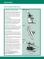
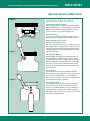
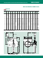
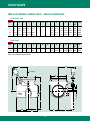
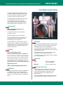
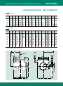
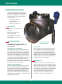
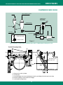
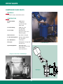
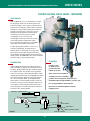
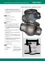
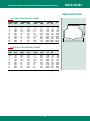
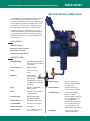
SEE GLOBE OR TRICENTRIC® VALVES FOR OTHER CHECK AND COMBINATION CHECK VALVES
CHECK VALVES
FREE FLOW REVERSE CURRENT VALVE
Atwood & Morrill Free Flow Reverse Current Valves
are designed to give maximum protection to
extraction steam turbines. Their rapid, tight closure
insures that the high level of energy found in feedwater heaters or process lines is quickly isolated
from the turbine in the event of a load rejection.
The power cylinder is designed to give a strong
closing moment to the valve when signalled to do
so by plant instrumentation. A lost motion feature
allows the valve disc to close independently of the
power cylinder.
APPLICATIONS
Turbine Protection
Extraction steam non-return
Bled steam non-return
Over 70 years of experience
SPECIFICATIONS
Design Standard:
ANSI B16.34 and applicable
international specifications
as required
Pressure Classes:
ANSI 150-1500
Sizes:
Cast construction
3"-44"
Materials:
Carbon steel,
alloy steel and
stainless steel
per ASTM specifications
or applicable international
standards
Cylinder Valves:
Solenoid operated air
valves or pilot operated
oil relay valves
Trim:
Stainless steel ASTM
A479 Type 410
Exerciser Valves:
Optional solenoid or
manual valves available
Seats:
Stainless steel overlay or
hardfacing alloy
Special Features:
Bonnet Design:
Bolted bonnet with
non-asbestos gasket
End Connections:
Butt weld or flange end
Power Cylinder:
Pneumatic or hydraulic
Drain Connections:
As required
Low friction stuffing
boxes - standard
Very low friction mechanical
seals - optional (can not
be overtightened)
Nondestructive examination as required by customer specification or
ANSI B16.34 Special Class
Limit Switches:
1, 2, or 3 SPDT or DPDT
switches available
Installation:
Horizontal or vertical
upflow as specified.
9
CHECK VALVES
FREE FLOW REVERSE CURRENT VALVE
Figure 1
DESIGN FEATURES
The important role of a Non-Return Valve as a protective device demands a high level of reliability. The
features found in all Atwood & Morrill Free Flow
Reverse Current Valves assure that reliability. These
features along with a high grade of workmanship
and materials assure a superior and completely
dependable valve.
Free Swinging Disc
(Fig. 1) Atwood & Morrill utilizes a basic swinging
disc Check Valve design. This uncomplicated design
provides independent movement of the disc in the
flow stream with fast closure upon loss or reversal
of flow. The valve disc is of sturdy construction to
prevent distortion under full design pressure.
Self Aligning Disc and Disc Arm
Figure 2
(Fig. 2) The disc and disc arm assembly are self aligning with the seat, assuring tight sealing. An internal
stop provides the proper degree of disc opening while
maintaining the edge of the disc within the flow
stream, so that flow reversal will cause closure.
Inclined Seat Design
(Fig. 3) Atwood & Morrill Free Flow Reverse Current
Valves have an inclined seat to improve the performance and operating characteristics of the valve. This
design offers advantages not available with other seat
configurations.
The inclined seat combined with flat disc and body
seat contact provides the best configuration available
in Check Valve design.
An opening angle of 75º from the vertical or 45º from
the inclined seat results in low pressure drop.
Figure 3
The reduced swing also enables the valve to close
quickly. Full opening with a vertical seat would
require a greater swing and a longer closing time.
The center of gravity of the disc assembly causes a
positive seating moment, therefore, the weight of the
disc is always acting to seat it and hold it firmly
against its seat. A portion of the disc weight can be
counterbalanced in larger valves to reduce pressure
drop at low flows, so the flow is not required to raise
the full weight of the disc.
The Atwood & Morrill inclined seat design
features - POSITIVE, TIGHT SEATING - FAST
CLOSURE - LOW PRESSURE DROP - all important
Check Valve considerations.
10
SEE GLOBE OR TRICENTRIC® VALVES FOR OTHER CHECK AND COMBINATION CHECK VALVES
CHECK VALVES
FREE FLOW REVERSE CURRENT VALVE
Figure 4
DESIGN FEATURES
Shaft and Bushing Assembly
(Fig. 4) Large diameter stainless steel shafts together
with hardened stainless steel bushings are used on all
A&M Free Flow Reverse Current Valves. The results
are lower stresses, less wear and longer life.
Positive Closing
The powerful spring in the power cylinder assures
rapid positive closing before reverse flow can occur.
Balanced Shaft Construction Internal Lost Motion Device
An “internally balanced” design is standard on all 12"
and smaller valves equipped with a closure assisting
cylinder. This feature eliminates stuffing box friction
and shaft end thrust which might prevent free swinging of the valve disc.
Figure 5
Valve Body & Bonnet
Atwood & Morrill employs a streamlined body contour designed for minimum flow resistance. Heavy
body wall thickness assures rigidity and resistance to
pipe strain distortion. A bolted top cover is provided
for ease of access to valve internals, thus the valve
need not be removed from the line for maintenance
and inspections.
External Lever
(Fig. 5) Valves of all sizes are available with shaft
mounted lever to manually exercise the valve. Larger
size valves are supplied with a counter weight to
reduce pressure drop at low flows to maintain full disc
opening and reduce disc slamming.
Figure 6
Cylinder Operated
(Fig. 6) Spring loaded positive closing air cylinders
can be provided on all Free Flow Reverse Current
Valves. Oil operated cylinders are also available. Oil
cylinders may be ordered with an optional oil relay
valve. Both types can be exercised by a lever operated
Test Valve or Solenoid Valve.
11
CHECK VALVES
FREE FLOW REVERSE CURRENT VALVE
The lever operated Air Test Valve equalizes pressure
on both sides of the cylinder piston so that the
spring force moves the piston downward and exercises the valve during operation.
APPLICATIONS FOR
TURBINE EXTRACTION SYSTEMS
Air Operated Systems
Figure 7 shows an A&M Air Operated Free Flow
Reverse Current Valve operated by turbine
overspeed trip and high water level in the
feedwater heater.
The system shown in Figure 8 differs from Figure 7
as the oil operated Air Relay Dump Valve is
replaced by an oil pressure switch which converts
the loss of oil pressure due to a turbine overspeed
trip to an electrical signal. This signal is connected
to the solenoid valve in series with the heater high
water level alarm circuit and trips the solenoid operated 3-Way Valve as in Figure 7.
The oil operated Air Relay Dump valve (normally
supplied by the turbine manufacturer) translates oil
pressure from the turbine overspeed trip system
into air pressure. With oil pressure established,
compressed air flows through the Air Relay Dump
Valve with the atmospheric vent closed. Upon loss
of oil pressure due to turbine overspeed trip, incoming air pressure is closed off, and the atmospheric
vent is opened to release air pressure from the
Check Valve cylinder. This action allows the spring
force to assist in closing the Free Flow Reverse
Current Valve. IT IS IMPORTANT THAT THE
SOLENOID OPERATED 3-WAY VALVE USED
ALLOWS FLOW IN THE REVERSE DIRECTION.
The quick exhaust valve shown in Figure 8 senses a
loss of pressure at its inlet and will shift allowing
the air cylinder to exhaust more rapidly through its
vent port. This valve can be used in any control system and is recommended whenever a solenoid
valve with a low Cv factor is used.
Local exercising of the Free Flow Reverse Current
Valve can also be accomplished by actuating an
integral test switch on the solenoid operated 3-Way
Valve. Using this method for exercising, the solenoid valve is exercised as well as the Free Flow
Reverse Current Valve.
The Solenoid Operated 3-Way Valve is installed in
the air supply line to the cylinder. Upon receipt (or
loss) of an electrical signal from the heater high
water level alarm, the Solenoid Valve trips, closing
the air supply and opening the vent to atmosphere.
Combinations of control systems shown in Figures
7 and 8 can also be used.
Air is exhausted from the air cylinder, and the
spring starts to close the valve.
Control for Turbine Extraction Systems
Figure 7
Figure 8
Free flow reverse
current valve
Steam to heater or
feed pump turbine
Steam to heater or
feed pump turbine
Extraction line
Turbine
Lever operated
3-way valve
Extraction line
Turbine
Electrical signal
from heater
high water
level alarm
Quick exhaust valve
Air supply
(60–125 PSIG)
(4.25–8.75 Kg/cm2)
Solenoid operated
3-way valve
Air to other free flow
reverse current valves
Electrical signal
from heater
high water
level alarm
or turbine trip
Air supply
(60–125 PSIG)
(4.25–8.75 Kg/cm2)
Oil operated air pilot valve
(Air exhaust) on turbine trip
12
Solenoid operated
3-way valve with
integral test button
CHECK VALVES
SEE GLOBE OR TRICENTRIC® VALVES FOR OTHER CHECK AND COMBINATION CHECK VALVES
FREE FLOW REVERSE CURRENT VALVE
DIMENSIONS
CLASS 150 - 300
SIZE
4
6
8
10
12
14
16
18
20
24
26
28
30
32
34
36
42
44
A
B
C
D
E
F
G
H
J
K
L
M
N
Weight
Lbs.
CV
14
14.00
21.00
22.7
24.75
24.00
26.00
29.00
31.00
37.00
44.00
46.00
50.00
50.00
53.00
53.00
66.00
66.00
7.75
7.75
9.63
11.00
11.50
12.13
14.00
15.50
17.38
19.50
22.50
23.50
25.00
25.00
26.50
26.50
33.00
33.00
10.75
10.75
13.69
15.50
15.50
16.75
19.25
21.50
23.00
24.75
27.00
28.50
28.25
28.25
34.38
34.38
45.00
45.00
9.00
9.00
12.50
16.00
17.88
19.50
21.75
25.00
26.25
30.00
34.00
34.00
36.75
36.75
40.00
40.00
49.00
49.00
6.75
6.75
7.00
9.00
9.31
11.38
11.25
13.25
14.63
12.63
–
–
–
–
32.13
32.13
35.38
35.38
–
–
–
–
–
18.00
19.50
21.50
24.50
24.50
27.50
27.50
29.00
29.00
31.25
31.25
34.75
34.75
–
–
–
–
–
16.00
17.13
17.00
20.88
27.00
24.25
24.25
23.13
23.13
28.00
28.00
41.63
41.63
–
–
–
–
–
24.50
26.25
25.88
31.75
42.00
34.00
34.00
30.75
30.75
40.13
40.13
64.25
64.25
12.06
12.06
13.25
14.75
15.75
16.63
17.88
19.63
22.63
22.63
23.88
23.88
24.25
24.25
26.63
26.63
29.88
29.88
15.13
15.13
16.13
17.63
18.63
19.50
20.75
22.50
25.50
25.50
26.75
26.75
27.13
27.13
29.50
29.50
32.75
32.75
3.88
3.88
.69
.88
.94
1.88
2.38
3.69
5.19
6.50
–
–
–
–
12.13
12.13
17.50
17.50
7.75
7.75
10.75
10.25
10.50
10.00
13.88
14.50
15.00
16.00
16.38
17.38
17.94
17.94
17.69
17.69
21.50
21.50
18.75
18.75
15.50
14.00
14.00
13.00
19.31
18.00
16.50
15.19
13.50
13.50
13.50
13.50
9.56
9.56
4.19
4.19
300
300
490
700
730
1100
1900
2100
3100
3700
3850
3960
5200
5200
5800
6100
14250
14250
510
870
1180
3180
4810
6300
8940
10720
13650
17050
24120
25120
29800
36200
–
40120
58320
58320
NOTE: ALL DIMENSIONS IN INCHES
G
F
CL VALVE
D
B
H
C
K
L
INLET
CL VALVE
SIZE
N
M
E
A
13
J
CHECK VALVES
FREE FLOW REVERSE CURRENT VALVE - TABLE OF DIMENSIONS
CLASS 400 - 600
SIZE
A
4
6
8
10
12
14
14
21
22.75
24.75
B
C
D
E
F
G
H
J
K
L
M
N
7.75
7.75
11.5
12
12.75
10.75
10.75
16.5
19.19
19.75
10
10
15
18.63
21.5
6.19
6.19
9
9.69
9.5
–
–
–
–
–
–
–
–
–
–
–
–
–
–
–
9.75
9.75
14.13
14.5
15.63
12.75
12.75
17
17.38
18.5
3.88
3.88
0.25
1.5
1.88
7.75
7.75
11.75
10.69
10.63
D
F
G
H
J
K
L
M
Weight
Lbs.
18.5
300
18.5
300
14.63 650
13.38 970
13
1470
CV
510
870
2500
4025
5960
CLASS 900
SIZE
A
B
C
8
10
21
22.75
11.5
12
19.81
21.38
E
18
19
10.38
9.88
–
–
–
–
–
–
15.13 18
0.25
14.5
17.38 1.5
N
Weight
Lbs.
11.75 14.63
800
10.69 13.38 1150
2500
4025
NOTE: ALL DIMENSIONS IN INCHES
G
F
CL VALVE
D
B
H
C
K
L
INLET
CL VALVE
SIZE
N
M
E
A
14
J
CV
SEE GLOBE OR TRICENTRIC® VALVES FOR OTHER CHECK AND COMBINATION CHECK VALVES
CHECK VALVES
COLD REHEAT CHECK VALVES
The Atwood & Morrill Cold Reheat Check is
a reliable, sturdy valve that protects the High
Pressure (HP) Steam Turbine from damage
caused by reverse flow during unit trip.
In newer Rankine and Combined Cycle plants
the Cold Reheat Check Valve must also
accommodate the increased demands of a
Turbine Bypass System and isolate the HP
Turbine Exhaust when the bypass is in use.
APPLICATIONS
Rankine and Combined Cycle Power
Plants with Reheat
Prevents Reheat Steam from Returning
to Turbine on Trip
Simplifies Hydrotesting of the Reheater.
Protects the High Pressure Turbine Exhaust
from Bypass Steam and Water when the
Turbine Bypass system operates.
42" Class 600 Cold Reheat
Check
Cold
Reheat Check Valve
Isolates High Pressure turbine exhaust when
auxiliary steam is supplied to the IP turbine in a
combined cycle unit, to synchronize the steam
turbine generator or start the gas turbine on a
single shaft machine.
DEMANDS
Quick Acting, Turbine Bypass Systems rapidly change
pressure and flow in the reheat piping, requiring the
Cold Reheat Check valve to close quickly.
FEATURES
The frequent Start ups and Shutdowns of Cycling
Units require the Cold Reheat Check valve to operate
several times per day.
Proven, Swinging Disc Design
Very Tight Sealing is necessary to prevent steam
and water from entering the HP turbine.
Wide, Flat, Non-jamming Seats for Tight Seal
Low pressure drop is important to overall combined
cycle unit performance.
Closure Assisting or Double Acting Air Cylinder
Smooth Flow Passages for Low Pressure Drop
AVAILABLE
In Line Maintenance through Bolted Top Cover
Inclined Seat for Short Travel & Quick Operation
Rugged Construction
Sizes:
20" to 42" and ANSI
Classes 300 to 600
Materials:
Carbon and Alloy Steels
Ability to Withstand Multiple Rapid Closures
SIZING AND SELECTION
OPERATION
Proper sizing requires verification of flow conditions. Ideally the disc should be in the Full Open
Position, Not Chattering or Fluttering in Flow
Stream. This allows for Low Wear and Low
Pressure Drop.
During normal operation, the Atwood & Morrill
Cold Reheat Check is open to forward flow.
It becomes a critical, quick closing valve which
protects the turbine during trips or equipment
failure.
The counterweight must be properly sized to allow
optimum operating conditions and full open disc.
15
CHECK VALVES
COLD REHEAT CHECK VALVES
BLOWDOWN COVERS
FOR COLD REHEAT CHECK VALVES
protector ring is available. When blowdown is
required but a cover is not provided, field fabrication
can be time consuming. If blowdown is expected to
carry a lot of debris, an additional disc may be useful.
For help meeting your system’s requirements, contact
A&M’s sales or service department.
The Atwood & Morrill Blowdown Cover allows
cleanout/blowdown of the pipeline to be easily and
efficiently done. The simple design bolts on in place
of the valve’s existing cover and provides an easy
blowdown connection. An optional blowdown disc
can also be supplied when large amounts of damaging debris are anticipated.
WELD END
BLOWDOWN COVER
LIFTING HOLES
CONSTRUCTION
The fabricated blowdown cover has a weld end for
easy pipe connection and lifting holes for easy
removal after blowdown is complete. The optional
valve disc is carbon or alloy steel.
OPERATION
INLET
After startup and blowdown, the Cold Reheat Check
Valve’s standard cover is replaced.
BLOWDOWN
DISC
When using Cold Reheat Check Valves consider
your blowout requirements carefully. When blowdown is started upstream of the Cold Reheat Check
Valve, remove the disc to prevent damage. A seat
A&M has 70 Years Extraction and Reheat Steam Service Experience.
44" Cold Reheat Check Valves
16
CHECK VALVES
SEE GLOBE OR TRICENTRIC® VALVES FOR OTHER CHECK AND COMBINATION CHECK VALVES
COLD REHEAT CHECK VALVES - TABLE OF DIMENSIONS
CLASS 300
SIZE
A
B
C
D
E
F
G
H
J
K
L
M
N
Weight
Lbs.
CV
28
30
32
34
36
42
44
46.00
50.00
50.00
53.00
53.00
66.00
66.00
23.50
25.00
25.00
26.50
26.50
33.00
33.00
28.50
28.25
28.25
34.38
34.38
45.00
45.00
34.00
36.75
36.75
40.00
40.00
49.00
49.00
–
–
–
32.13
32.13
35.38
35.38
27.50
29.00
29.00
31.25
31.25
34.75
34.75
24.25
23.13
23.13
28.00
28.00
41.63
41.63
34.00
30.75
30.75
40.13
40.13
64.25
64.25
23.88
24.25
24.25
26.63
26.63
29.88
29.88
26.75
27.13
27.13
29.50
29.50
32.75
32.75
–
–
–
12.13
12.13
17.50
17.50
17.38
17.94
17.94
17.69
17.69
21.50
21.50
13.50
13.50
13.50
9.56
9.56
4.19
4.19
3960
5200
5200
5800
6100
14250
14250
25120
29800
36200
–
40120
58320
58320
CLASS 600
SIZE
A
B
C
D
E
F
G
H
J
K
L
M
N
Weight
Lbs.
CV
14
16
18
20
24
26
28
30
32
34
36
38
28.00
28.00
30.00
33.00
44.00
44.00
50.00
50.00
55.00
55.00
59.00
59.00
14.00
14.00
15.00
17.38
22.00
22.00
27.13
27.13
27.50
27.50
29.50
29.50
21.75
21.75
25.38
29.50
38.63
38.63
32.00
32.00
36.50
36.50
43.75
43.75
24.00
24.00
27.00
29.25
37.00
37.00
37.00
37.00
42.00
42.00
47.50
47.50
11.25
11.25
12.50
16.00
–
–
–
–
–
–
–
–
19.00
19.00
22.25
25.81
29.25
29.25
29.50
29.50
31.75
31.75
33.50
33.50
17.13
17.13
16.88
20.88
22.75
22.75
26.00
26.00
32.00
32.00
35.25
35.25
26.25
26.25
26.38
31.75
34.00
34.00
35.13
35.13
45.50
45.50
50.13
50.13
17.88
17.88
19.00
22.63
23.75
23.75
24.25
24.25
27.13
27.13
28.50
28.50
20.75
20.75
21.88
25.50
26.63
26.63
27.13
27.13
30.00
30.00
31.88
31.88
4.19
4.19
4.19
4.19
9.50
9.50
8.25
8.25
11.00
11.00
13.75
13.75
13.81
13.81
14.00
16.00
16.50
16.50
19.81
19.81
18.69
18.69
18.31
18.31
19.31
19.31
17.56
17.56
12.25
12.25
13.50
13.50
10.75
10.75
8.00
8.00
2100
2100
2750
3100
7600
7600
7800
7800
9500
9500
15000
15000
8050
8470
10780
13460
19960
23560
27500
32330
37650
43425
49665
56425
NOTE: ALL DIMENSIONS IN INCHES
F
G
CL VALVE
D
B
H
C
K
L
INLET
CL VALVE
SIZE
N
M
E
A
17
J
CHECK VALVES
COMPRESSOR CHECK VALVES
The Atwood & Morrill Co. Inc. Compressor
Check Valve is designed to provide positive
protection for the blower or compressor. It is
installed in the compressor discharge line
when specified as:
•
•
•
•
Tight sealing pressure
Low differential pressure
Power assisted
Dashpot, non-slam valve
APPLICATIONS
Fluid Catalytic Cracking Air Blower
Discharge
Compressor Discharge and
Process Application
Fluids: Hydrocarbon (Cracked
Gas), Ethylene, Propylene, Other
Process Fluids
OPERATION/FEATURES
32" Class 300 Compressor
Discharge Check Valve
The A&M Compressor Discharge Check Valve
is important in providing protection for
critical equipment.
OIL DASHPOT
Years of experience with blower check valves has
indicated that the valve disc will tend to flutter at
various flow rates. This constant motion during
operation may result in premature packing wear
and/or valve failure. To prevent this flutter motion,
A&M Compressor check valves are supplied with an
oil dashpot which can be adjusted to dampen the
motion and reduce disc slamming.
CLOSURE ASSIST AIR CYLINDER
The Compressor Check Valve operates normally
with the disc in the open position for long periods.
To ensure the check valve will close in the event of
a blower/compressor trip, it is furnished with a closure assist air cylinder. Upon loss of power to the
drive device of the blower/compressor, a three-way
solenoid valve is de-energized. When the solenoid
valve is tripped, the side air cylinder is vented
allowing the internal spring to apply a closing force
to the lever arm which, in turn, rotates the shaft and
disc assembly to the closed position.
DEPENDABILITY
Compressor Check Valves are protective devices
critical to safeguard the compressor/blower systems.
A&M valves are designed to be completely reliable
over extended periods of time. Severe damage may
occur if the disc in a check valve is prevented from
self closure. The A&M Compressor Check Valve
offers positive protection against sticking or
hang-up and insures rapid, reliable closing in
the event of a trip-out or system shutdown.
EXTERNAL COUNTER WEIGHTS
External counter weights help the valve remain in
the full open position at normal operating flow.
These weights counter balance approximately 50%
of the disc closing moment assuring the valve disc
will be fully open providing the lowest pressure
drop possible. A&M check valves will be fully open
at lower flow rates compared to conventional swing
or wafer type check valves.
18
CHECK VALVES
SEE GLOBE OR TRICENTRIC® VALVES FOR OTHER CHECK AND COMBINATION CHECK VALVES
COMPRESSOR CHECK VALVES
PRESSURIZED FLU GAS
COMPRESSOR
DISCHARGE
CHECK VALVE
CATALYST
BED
REGENERATOR
REACTOR
REGENERATOR AIR
FCC FEED
AIR SUPPLY
TRIP SIGNAL
HAND TEST VALVE
MOTOR/
GEAR
SOLENOID VALVE
DRIVE
DEVICE
Figure 1
AIR BLOWER/
COMPRESSOR
Typical Installation of A&M Compressor Discharge Check Valve in a Fluid Catalytic Cracking Process Unit
Bolted Bonnet design allows
full access to internals in-line
5
3
3
5
Self Aligning disc
and disc arm
4
4
2
INLET
1
AIR
CYL
1 - Closure Assist Air Cylinder
2 - Oil Dashpot
3 - Counterweights act to counterbalance the disc providing the lowest pressure drop
4 - Protective Sleeves cover external linkages
5 - Lubricated Stuffing Boxes
19
CHECK VALVES
COMPRESSOR CHECK VALVES
MATERIALS
Cast Carbon, Alloy and Stainless Steel
CONSTRUCTION
Design Standard:
ANSI B16.34
Sizes:
4 - 60 inches
sizes 44" thru 60"
(fabricated)
Pressure Ratings:
ANSI Class 150
through 2500
Cover Design:
Bolted Bonnet
(pressure seal for class
900 and higher)
End Connection:
Butt weld or flanged
Positive Closing Device: Spring loaded cylinder
(air controlled)
Disc Stabilization:
Oil Dashpot
Body Type:
Swinging disc design with
inclined seat
Optional Equipment:
Hand Test valve
Three-way solenoid valve
Limit switches
Protective Sleeves
Actual Oil Dashpot
Compressor Check Valve with Oil Dashpot
Oil Dashpot
20
SEE GLOBE OR TRICENTRIC® VALVES FOR OTHER CHECK AND COMBINATION CHECK VALVES
CHECK VALVES
POSITIVE CLOSING CHECK VALVES - FEEDWATER
APPLICATION
Atwood & Morrill Co., Inc. manufactures Positive
Closing Check Valves for the discharge lines of
boiler feed pumps. These valves provide positive
protection for feedwater systems and can prevent
damage to costly pumping equipment. Failure to
provide such protection could cause serious
damage to the feed pumps and their drive
mechanisms and may result in a plant
outage with a loss of revenues far
exceeding the initial investment necessary
to provide protective equipment. Figure
No. 1 illustrates the typical use of an A&M
Valve with a motor-driven feed pump.
Positive Closing Check Valves can be used
to protect pumps that are motor-driven,
turbine-driven, or those that are run by drive
shaft off the main turbine thereby improving
the reliability and dependability of the entire feedwater system. The A&M Valve also offers minimum
pressure drop for every day operation.
FEATURES
DESCRIPTION
Positive, power
assisted closure
provides fast and
reliable protection.
Atwood & Morrill Positive Closing Check Valves
achieve reliable and rapid closure by means of an
auxiliary, spring loaded cylinder, usually actuated
by compressed air. The positive closing cylinder
acts to close the disc of the valve through a simple
engaging mechanism. But, the engaging mechanism
does not permit the cylinder to open the valve. In
the case of a turbine drive, an Oil Operated Air
Relay Valve is used to translate turbine control oil
pressure to air pressure. An alternate method is to
use a switch, actuated by the turbine trip mechanism, operating a solenoid valve which controls air
pressure to the closing cylinder.
Valve closure before backflow.
“Double protection”; including
positive closure and power assisted closure.
Streamlined flow design minimizes pressure drop.
Fast closing minimizes water hammer.
Flat seats for maximum tightness without
wedging action.
ELECTRIC POWER SUPPLY
TEST VALVE
MOTOR
AIR SUPPLY
PUMP
Figure 1
CHECK VALVE
WITH AIR CYL.
21
3-WAY SOLENOID VALVE
VENT TO ATMOS.
CHECK VALVES
POSITIVE CLOSING CHECK VALVES - FEEDWATER
OPERATION
Cross Section Showing Positive Closing Cylinder & Shaft
When the piston of the closing cylinder is pushed
upward by air pressure, the disc assembly of the
valve is free to swing from a closed to a wide open
position solely in response to feedwater flow. Disc
movement is completely independent of the shaft.
A stop on the back of the disc holds it at a slight
incline into the flow when the valve is wide open.
Normal velocities swing the disc to the full open
position and the stop prevents undue flutter or
movement.
WATER HAMMER PROTECTION
High pressure Boiler Feed Pumps operating at high
speeds and low inertia can lose speed and stop
almost instantaneously, particularly in close coupled
systems with short runs of pipe. Should one of
these pumps be tripped-out or shut-off, it could go
into reverse rotation in a matter of seconds. If
reverse flow starts due to the slow closing or failure
of a check valve, serious water hammer will result
when the valve finally closes. In systems where parallel pumps are used, if one pump is shut down,
any surges caused by the working pump will be isolated from the pump which the valve is protecting.
OUTLET
Cross Section Showing Inclined Seat & Swinging Disc
Tests and experience have shown that when an
A&M Positive Closing Check Valve is used, water
hammer is reduced to a minimum and the pump is
assured maximum protection against reverse flow.
WATER HAMMER TESTS AND RESULTS
Portions of oscillograph tapes of tests made on production line A&M Valves are shown. The tests were
conducted by an independent research facility to
verify the advantages of fast closing and to demonstrate the effect of positive closing over a swinging
disc check valve which was not positive closing. No
numerical values are indicated. The following tests
were run with the valve in the discharge of a motor
driven pump.
I. A Swinging Disc Check Valve with added weight at
the outer edge of the disc, with the valve depending only on gravity for its closing moment.
INLET
II. The same valve as in (I.) above, but with a positive closing cylinder arranged so that air pressure
could be released simultaneously with the opening of the electrical circuit of the motor drive.
The trace lines indicate pressure during the test and
at the moment of valve closure. The height of the
line indicates the magnitude of the water hammer.
22
SEE GLOBE OR TRICENTRIC® VALVES FOR OTHER CHECK AND COMBINATION CHECK VALVES
CHECK VALVES
POSITIVE CLOSING CHECK VALVES - FEEDWATER
Atwood & Morrill valve provides double protection
with two methods of closure. First, the A&M Valve
acts as a self-closing Check Valve when air pressure
is admitted to the cylinder. Second, it acts as a
Power Actuated Valve when air pressure is released
from the cylinder on a trip-out.
A comparison of the tapes shows the almost
amazing results obtained when the positive closing
cylinder was used. During the series of tests, it was
also demonstrated that sluggish or retarded closing
would severely increase water hammer, further
proving the advantage of fast, positive closing.
When summarizing the results of the tests, the
laboratory report states: “This intensity of water
hammer (i.e., when positive closing was used) was
almost inaudible and with no apparent vibration.”
MINIMUM PRESSURE DROP
AND FULL FLOW EFFICIENCY
A&M Boiler Feed Pump Check Valves assist in keeping pressure drop in the feedwater piping system at
a minimum, particularly when a single A&M Valve
replaces a “double valve” installation. The streamlined characteristics of the A&M design make it an
efficient valve to use, which is particularly important
when longterm installed costs are considered.
Valve Closure Test Tapes
PRESSURE
SURGE
0.1 SEC.
“INTERNAL BALANCE”
The A&M Valve is designed so that the disc assembly is “pressure balanced”. This means that the
disc assembly is free to swing independently of
the operating shaft. The disc is not subject to
stuffing box friction or end-thrust tending to force
it against the side of the valve. The operating shaft,
which passes through the stuffing box is stationary
under normal operating conditions. It is rotated
only on a trip-out or shut-down by the closing cylinder, which has ample power to overcome stuffing
box friction or other causes for sticking. In very
high pressure installations, the operating shaft is
“pressure balanced” by using double stuffing
box construction.
PIPE
STRESS
TIME
With Added Weight On Outer Edge of Disc
PRESSURE
SURGE
0.1 SEC.
PIPE
STRESS
TIME
With Positive Closing Cylinder
ONE-PIECE BODY CONSTRUCTION
AND SIMPLE DESIGN
A&M Boiler Feed Pump Check Valves are designed
with a one-piece body and relatively few moving
parts to minimize operating difficulties and simplify
maintenance. Once installed, a valve can be inspected easily without removing it from line and the
internals can be removed through the top cover.
The closing mechanism can also be inspected
easily without removing it from the valve by taking
off the cylinder to expose the piston. The cylinder
and piston assembly can then be examined for
wear. If it becomes necessary to remove the piston,
the threaded piston rod allows gradual backing off
of the spring load so the rest of the cylinder can
be dismantled without danger or the need for any
special tools.
FEATURES AND DESIGN ADVANTAGES
DEPENDABILITY AND POSITIVE CLOSURE
Positive Closing Check Valves are protective devices
that must be completely reliable over extended
periods of time. An average pump is “on stream”
for a number of months and flow holds the valve in
a wide open position for long intervals. Serious
damage may result if foreign matter or sediment
accumulates between the shaft and the bushings
and retards or prevents free self closure. A&M
valves offer positive protection against sticking or
hanging-up and insure rapid, reliable closing in the
event of a trip-out or shutdown.
DOUBLE PROTECTION
Some plants use two simple check valves in series
as a means of insuring positive closure. Such double valving may be unnecessary, since a single
Atwood & Morrill does not use internal springs,
which are difficult to replace. A&M provides a
closing spring external to valve which is readily
23
CHECK VALVES
POSITIVE CLOSING CHECK VALVES - FEEDWATER
DIMENSIONS
accessible and can be removed from the cylinder
assembly with ease. Possible spring failure could
not seize the shaft or prevent self-closing of
the valve.
Class 1500
SIZE
END TO END
Cv
4
6
8
10
12
14
16
13
15
18
23
25
25
29
357
826
1603
2585
3926
3926
5927
END TO END
Cv
SPECIFICATIONS
Size:
3" through 24" standard
Pressure Ratings:
ANSI Class 400, 600, 900,
1500, 2500
(Special and higher
ratings as applicable)
Materials:
Cast steel with stainless
steel or Cobalt Alloy Hard
Facing trim. Other materials furnished on request.
Cover Design:
Pressure Seal, Bolted
Bonnet as specified.
Closing Device:
Spring loaded cylinder
(air controlled).
Body Type:
Swinging disc design with
inclined seat. Suitable for
full ANSI test pressures.
Disc Assembly:
One-piece construction,
pressure balanced against
lateral thrust. Positive
stop on disc. Disc suitable
for full pump shut-off
pressure.
Shaft Bearing Design:
Class 2500
SIZE
4
6
8
10
12
14
16
18
Integral stainless steel
facings on both disc and
body. Cobalt Alloy Hard
Facings also available.
Stuffing Box Packing:
Graphoil type. Leak-off
bushings available.
357
826
1603
1603
2585
3926
3926
5927
NOTE: ALL DIMENSIONS IN INCHES
2
1
Single stuffing box for
lower pressures. Double
stuffing box for higher
pressures.
Outboard shaft support
bearing on cylinder side.
Shaft bushings are nitrided stainless steel.
Seats:
13
18.5
23.5
23.5
28
35
35
41
3
INLET
4
No.
1
2
3
4
24
Part
Body
Cover
Disc
Seats
SEE GLOBE OR TRICENTRIC® VALVES FOR OTHER CHECK AND COMBINATION CHECK VALVES
CHECK VALVES
SWING CHECK VALVE - BALANCE OF PLANT
The Atwood & Morrill Swing Check Valve is
designed to effectively prevent reverse flow and
is ideally suited for liquid, steam and other gases
requiring assured performance, tight shutoff and
low maintenance.
APPLICATION
Condensate pump discharge
Heater drains
Liquid, steam and gas check valve
DESCRIPTION
A unique one piece disc and disc arm that
cannot spin or flutter. The valve is flow
engineered to hold the disc in the full open
position during a wider range of flows, and
the swinging disc design prevents wedging
or jamming.
Wide, flat, permanently aligned seats that
minimize leakage.
Stainless steel seat facings and hardsurfacing
alloy available.
Bolted bonnet on 150 through 600 class valves
and pressure seal bonnet on 900 through 1500
class valves.
An internal bracket on 21/2 -18 inch valves,
eliminates side body penetrations for the shaft,
removing two potential leak paths.
For larger sizes, a conventional double bearing
cover design is used.
Internal
bracket
SPECIFICATIONS
Size:
21/2 - 48 inch
Pressure Ratings:
ANSI Class 150-1500
Materials:
Carbon steel, Alloy steel
or stainless steel, all with
stainless steel trim.
Internal disc
and arm
Wide flat
seats
25
Rugged
disc stop
CHECK VALVES
SWING CHECK VALVE
CLASS 150, BOLTED BONNET
NOMINAL SIZE
INCH
MM
A DIMENSION
INCH
MM
B DIMENSION
INCH
MM
2.5
3
4
6
8
10
12
14
16
18
20
24
26
30
12
12
12
14.5
17
18.5
20.5
23
25
27
31
37
44
50
5.25
5.25
5.375
6.5
8.5
9.5
10.75
11.5
13
14.75
23.125
23.75
27
25.625
65
75
100
150
200
250
300
350
400
450
500
600
650
750
305
305
330
368
432
470
521
584
635
686
787
940
1118
1270
WEIGHT
LB.
KG.
133
133
137
165
216
241
273
292
330
375
587
603
686
651
95
95
110
140
235
300
450
550
660
1015
2474
3445
3730
4608
43
43
50
64
107
136
204
249
299
460
1113
1550
1679
2074
Cv
198
208
370
868
1672
2688
3983
4892
6582
8559
16400
21900
27200
36800
CLASS 300, BOLTED BONNET
NOMINAL SIZE
INCH
MM
A DIMENSION
INCH
MM
B DIMENSION
INCH
MM
2.5
3
4
6
8
10
12
14
16
18
20
24
26
30
12
12
13
15.5
17.5
20
21.5
24
25
27.5
31
37
44
50
5.25
5.25
6
7.5
9.25
10.75
12
13
14
15.5
23.125
25.125
28.625
25.625
65
75
100
150
200
250
300
350
400
450
500
600
650
750
305
305
330
394
445
508
546
610
635
699
787
940
1118
1270
WEIGHT
LB.
KG.
133
133
152
191
235
273
305
330
356
394
587
638
727
651
95
95
110
200
310
450
669
698
825
1215
2474
3495
3780
5030
43
43
50
91
141
204
299
313
374
551
1113
1573
1701
2264
Cv
198
204
370
868
1628
2651
3838
4892
6420
8559
16400
21900
27200
36800
CLASS 600, BOLTED BONNET
NOMINAL SIZE
INCH
MM
A DIMENSION
INCH
MM
B DIMENSION
INCH
MM
2.5
3
4
6
8
10
12
14
16
18
20
24
26
30
12.5
12.5
13.5
15.5
17.5
20
21.5
25
27
31
40
40
50
52
6.25
6.25
7
9.25
10.5
12.25
13
14.5
15.52
17.5
34
31.25
28.5
37.5
65
75
100
150
200
250
300
350
400
450
500
600
650
750
318
318
343
394
445
508
546
635
686
787
1016
1016
1270
1321
WEIGHT
LB.
KG.
159
159
178
235
267
311
330
368
394
445
864
794
724
953
125
125
150
250
375
550
780
975
1315
1950
4000
5270
5700
8300
26
57
57
68
113
170
249
354
442
596
885
1800
2372
2565
3735
Cv
187
193
370
868
1796
2651
3838
4833
6295
8290
15300
17500
31650
35700
B
A
SEE GLOBE OR TRICENTRIC® VALVES FOR OTHER CHECK AND COMBINATION CHECK VALVES
CHECK VALVES
SWING CHECK VALVE
CLASS 900, PRESSURE SEAL BONNET
NOMINAL SIZE
INCH
MM
A DIMENSION
INCH
MM
B DIMENSION
INCH
MM
2.5
3
4
6
8
10
12
14
16
18
20
24
12.5
12.5
13
15.5
17.5
22.5
27
27
31
34
44
44
7.5
7.5
8.75
11
12.5
19
17.25
17.25
20
22
28.37
29.5
65
75
100
150
200
250
300
350
400
457
500
600
318
318
330
394
445
572
686
686
787
864
1118
1118
WEIGHT
LB.
KG.
191
191
222
279
318
483
438
438
508
559
720
750
95
43
95
43
120
54
235
107
370
168
800
363
1150
522
1150
522
1600
726
2300 1043
6380 14036
6000 13200
Cv
202
209
363
801
1517
2346
3658
4207
5629
7558
15235
18878
CLASS 1500, PRESSURE SEAL BONNET
NOMINAL SIZE
INCH
MM
A DIMENSION
INCH
MM
B DIMENSION
INCH
MM
2.5
3
4
6
8
10
12
14
16
18
12.5
12.5
14
16.5
19.5
25
30
30
34.5
38
8
8
8.75
13.5
15.5
19.5
23
23
27
30
65
75
100
150
200
250
300
350
400
450
318
318
356
419
495
635
762
762
876
965
WEIGHT
LB.
KG.
203
203
222
343
394
495
584
584
686
762
140
140
336
800
1200
1600
2170
2170
2800
3500
27
64
64
152
363
544
726
984
984
1270
1588
Cv
202
209
345
801
1517
2346
3658
4207
5629
7558
B
A
CHECK VALVES
RECOMMENDATIONS AND REQUIREMENTS
MAINTENANCE, INSPECTION, EXERCISING
ORDERS AND INQUIRIES
Atwood & Morrill Co., Inc. recommends a standard
program of maintenance, inspection, and exercise
for their products. For more information, please
refer to the service manual supplied with each
valve, or contact your local A&M representative or
the home office in Salem, Massachusetts.
When specifying Check Valves, please supply:
1. Flow Conditions: Temperature, Pressure and
Flow Rate
2. Style of valve (series or description)
3. Number of valves
4. Service
INSTALLATION RECOMMENDATIONS
5. Size or Flow capacity
For longest service life of these or any check valves,
installation near sharp bends, elbows, eccentric
reducers or expanders or other valves should be
avoided. When possible, a length of 10 pipe diameters of straight pipe upstream and 5 pipe diameters
of straight pipe downstream is recommended.
6. Operating and design temperatures and
pressures
7. Special material requirements
8. Maximum allowable pressure drop
9. Pipe run (horizontal or vertical)
Atwood & Morrill Check Valves are engineered
products. It is strongly recommended that a
representative or factory sales engineer be
consulted before selecting a valve.
10. Mounting of auxiliary equipment (left or right
side when facing inlet)
11. Other pertinent data
12. Accessory equipment
13. Available air and electrical supply
28