1
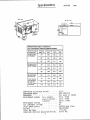
.\)
.d
Service Manual
SERIES
MODULAR
900
CUBED
ICE MAKER
1/91
161951805
T A B L E
O F
C 4 0 N T E N T S
1
............................
TABLE OF CONTENTS . . . . . . . . . . . . . . . . . . . . . . . . . . .
2
SPECIFICATIONS . . . . . . . . . . . . . . . . . . . . .
...... 3
INSTALLATION AND START-UP . . . . . . . . . . . . . . . . . . . . .
41-10
REFRIGERANT CIRCUIT REMOTE CONDENSER UNITS . . . .
. . . . . . . . 11
ELECTRlCAL CIRCUIT SEQUENCE OF OPERATION . . . . . . . . . . . . . . 1 2
ADJUSTMENT FOR I C E BRIDGE THICKNESS . . . . . . . . . . . . . . . . . 12 .
ADJUSTMENT AND CHECK-OUT FOR OPTICAL HARVEST - B I N SENSOR . . . . . 13
WIRING AND SCHEMATIC DIAGRAMS . . . . . . . . . . . . . . . . . . . 14-17
S A N I T I Z I N G AND CLEANING PROCEDU'RE . . . . . . . . . . . . . . . . . . 18
WATERTREATMENT . . . . . . . . . . . . . . . . . . . . . . . . . .
19
WINTER STORAGE . . . . . . . . . . . . . . . . . . . . . . . . . . .
20
CLEANING THE CONDENSER . . . . . . . . . . . . . . . . . . . . . . .
20
SERVICE ANALYSIS . . . . . . . . . . . . . . . . . . . . . . . . . .
21-23
INTRODUCTION
."
1
I
5,
INSTRUCTIONS FOR REMOVAL AND RE-INSTALLATION
....................
PARTS L I S T . . . . . . . . . . . . . . . . . . . . . . . . . .
...
ILLUSTRATED PARTS BREAKDOWN . . . . . . . . . . . . . . . . . . . .
REMOTE CONDENSER TLLUSTRATED PARTS BREAKDOWN . . . . . . . . . . . .
OF SOLID STATE CONTROL
2
24
25
26
27
INTRODUCTION
Ue have s t r i v e d t o produce a q u a l i t y product.
thus i n s u r i n g trouble-free operation.
The design has been kept simple,
This manual has been prepared t o a s s i s t servicemen and users w i t h information
concerning i n s t a l l a t i o n , construction and maintenance of the i c e making
equipment. The problems o f the serviceman and user have been given special
a t t e n t i o n i n the development and engineering o f our icemkers.
Ifyou encounter a problem which i s not covered i n t h i s manual, please f e e l
free t o w r i t e o r c a l l . We w i l l be hap,py t o a s s i s t you i n any way we can.
-
Uhen w r i t i n g , please s t a t e the model and s e r i a l number of the machine.
Address a1 1 correspondence to:
A Product of IMI Cornclius Americas Inc.
2421 - 15th St. S.W. P.O. Box f527
Mason City, I A 50401
Phone 5 15-424-6150 I 1-800-)83-0385
FAX 5 15-424-4305
1
Specifications
Model Number Ambient
(Condenser)
Temp O F
AC-900-SS-MH
(Air Cooled)
W C-900-SS-MH
(Water Cooled)
RC-900-SS-MH
(Remote Air)
Note: Remote
unit designed
for use with
CS-120 remote
condenser.
900
incoming Water Temp a
50a
70°
80°
70°
696
620
594
800
650
582
556
900
580
511
494
70°
674
610
552
800
665
610
545
900
666
60 1
529
50°
741
650
620
509
1100
I
SERIES
I
449
I
4 29
I
.....
...........
..............
.
....
COMPRESSOR ELECTRICAL RATING
COMPRESSOR MODEL
CONDENSER.
REFRIGERANT CHARGE
( a i r cooled). . .
(water cooled).
(remote).
R E FR IGERANT CONTROL . . . . . . . . .
TXV SUPERHEAT SETTING . . . . . . . .
I N L E T WATER SUPPLY
VULTAGE
TOTAL AMP DRAW . . . . . . . . . . . .
CRANKCASE PRESSURE REGULATOR SETTING .
..........
...............
3
I
2 H.P.
CRDl-0200-PFV
Air, water o r remote
70 02. R-502
43 0 2 . R-502
270 0 2 . R-502
TXV
6O
3/8"SAE male f l a r e
208-230/60/1
13.8 amps
50 P S I f l a x .
I N S T H U C T I O N S
--i N S T A L , - L A ? I O N
A.
6.
UNPACKING
----__--1.
Uncrate machine and/or b i n by removing the staples from around the bottom
of cardboard c r a t e and 1 i f t o f f .
2.
Remove b o l t s fastening the c r a t e s k i d t o the bottom of t h e u n i t . I f
auxiliary.1egs have been purchased f o r the bin, they should be i n s t a l l e d
a t t h i s time.
LEVELING
I f legs are used,.adjust the l e v e l i n g legs of t h e storage b i n u n t i l the
u n i t i s l e v e l and a l l four ( 4 ) legs are i n s o l i d contact w i t h the f l o o r .
Leveling i s very impartant t o obtain proper d r a i n i n g and t o maintain the
proper l e v e l i n the water pan o f the i c e cuber.
NOTE: If' the b i n i s t o be i n s t a l l e d f l u s h t o the f l o o r , the machine must
be sealed t o the f l o o r w i t h an approved mastic such as Sears rY3803-0 Caulk,
Dow R.T.V. 101, 102 o r G. E. 731, 732. This i s an N.S.F. requirement and
i s the r e s p o n s i b i l i t y o f the i n s t a l l e r .
C.
UNIT LOCATION
I
I
_
-
1.
Allow a t l e a s t a minimum o f s i x ( 6 ) inches a t the r e a r and side o f the
i c e machine f o r proper a i r c i r c u l a t i o n .
2.
This u n i t has been designed t o be i n s t a l l e d i n an indoor l o c a t i o n which
i s clean and which can be adequately ventilated; t h e a i r and water
temperatures should never exceed 100 degrees nor fa1 1 below 50 degrees.
(Temperatures above 100 degrees w i l l c u t t h e i c e making capacity below
an economical l e v e l ; temperatures below 50 degrees w i l l cause a
m a l function o f thermostatic sensors.
3.
0.
The u n i t should be located where a i r c i r c u l a t i o n i s n o t r e s t r i c t e d .
The u n i t should n o t be located near a k i t c h e n g r i l l . A i r which contains
grease vapors w i l l deposit grease on the condenser. The condenser
should always be kept clean.
U N I T SET-UP
1.
Take o f f f r o n t panel of machine arid remove hardware bag o r service
manual envelope w i t h the water s t r a i n e r enclosed.
2.
Mount the i c e maker t o the top o f the i c e storage b i n o r adapter i n
the proper p o s i t i o n over the i c e drop opening. The i c e maker must
then be sealed both on the outside and the i n s i d e bottom edges w i t h
an approved N.S.F. mastic such as Dow S i l a s t i c #732, 734 o r General
E l e c t r i c RTV #101, 102. This i s an N.S.F. requirement and the
r e s p o n s i b i l i t y o f the i n s t a l l e r .
3.
Remove shipping tape from evaporator c u r t a i n s .
4
I N S T A L L A T I O N
E.
I N S T R U C T I O N S
C O N T ' D .
REMOTE CONDENSERS
Remote condensers should be i n s t a l l e d above the i c e machine and i n a l e v e l
configuration. They are connected t o t h e i c e making u n i t by copper t u b i n g
and l i n e valves. The female h a l f o f the l i n e valve i s mounted on the i c e
making u n i t and the remote condenser. The male h a l f i s soldered on the
tube ends when tubing k i t s illy! provided w i t h the machine. Iftubing k i t s
are n o t provided, the male h a l f o f the l i n e valves w i l l be provided i n a
valve k i t and t h e i n s t a l l e r w i l l mount them on the tubing he provides.
1.
NOTE: WHEN VERTICAL LINES ARE INVOLVED I N THE INSTALLATION, FOLLOW
STANDARD REFRIGERATION PRACTICES FOR VERTICAL LINES TO ASSURE POSITIVE
O I L RETURN TO THE COMPKESSOR. VERTICAL L I F T TO BE NO MORE THAN 15 FEET.
2. NOTE:
WE 00 NOT RECOMMEND TU8ING RUNS OF MORE THAN 40 FEET.
3.
THE SEALS FOR THE L I N E VALVES WILL BE FOUND I N AN ENVELOPE
MAKE SURE THEY ARE USED.
NOTE:
ON THE REMOTE CONDENSER.
4.
NOTE: REMOVE CAP PLUGS FROM ALL L I N E VALVES BEFORE MAKING VALVE
CONNECTIONS WITH THE SEAL
I
5.
NOTE: A LOW VOLTAGE ELECTRICAL CONTROL CIRCUIT MUST RE F I E L D WIRED
BETWEEN THE ICE MACHINE AND THE REMOTE CONDENSER RELAY. THOSE WIRES
SHOULD BE RUN WITH THE TUBING DURING INSTALLATION. REFER TO APPLICABLE
WIRING DIAGRAMS.
6. WHEN THE L I N E VALVES ARE CONNECTED TO EACH OTHER THE REFRIGERANT CIRCUIT
IS COMPLETE. EACH VALVE HALF HAS I T S OWN SHUT OFF WHICH MUST BE FULLY
OPENED TO ALLOW THE REFRIGERANT TO FLOW THROUGH THE SYSTEM BEFORE I T
IS STARTED.
The i c e making u n i t u t i l i z i n g
w i t h the r e c e i v e r holding the
be r e q u i r e d upon i n s t a l l a t i o n
condenser i s operating under,
a remote condenser i s shipped from the f a c t o r y
r e f r i g e r a n t charge. A d d i t i o n a l r e f r i g e r a n t may
depending upon the ambient c o n d i t i o n s the remote
the condenser and l i n e s i z i n g .
A t h r e e way head pressure c o n t r o l valve i s used t o maintain a r e l a t i v e l y
c o n s i s t e n t head pressure between 180 and 200 PSI f o r R-502 i n the r e c e i v e r i n
c o l d ambient conditions t o insure a good harvesting o r d e f r o s t i n g of the i c e
slabs on the evaporator. 8ecause o f t h i s valve some l i q u i d r e f r i g e r a n t w i l l
be h e l d i n the condenser.
NOTE: THE HEAD PRESSURE CONTROL VALVE WILL NOT OPERATE CORRECTLY WHEN A
TOTAL PRESSURE DROP OF 14 POUNDS OR MORE IS CREATED BETWEEN THE IC€ MAKING
UNIT, THROUGH THE TUBING TO THE REMOTE CONDENSER, THE CONDENSER AND THE
RETURN TUBING TO THE I C E MAKING UNIT.
The remote condenser requires a separate power supply from the i c e making
u n i t . Refer t o the remote condenser w i r i n g diagram.
5
S N
------F.
S T A L L A T I O N
MAKE
-ELECTRICAL
Requirements:
I M -.S-- Y H U C 7 I O N S
C O N T ' D .
POWER SUPPLY
COkNECTION
__-__--.
208-230/60hz.
1 ph. o r 220V 50hz. 1 ph. when used
REFER TO SERIAL PLATE FOR MINIMUM CIRCUIT AMPACITY AND MAXIMUM TIME
DELAY FUSE SIZE.
ALL WIRING MUST CONFORM TO NATIONAL AND LOCAL ELECTRICAL CODES.
G.
MAKE PLUMBING CONNECTIONS
Water supply
-
( I n s t a l l per l o c a l codes)
The water i n l e t connection t o the u n i t i s a 3/8" f l a r e male connections
located a t the r e a r o f t h e i c e machine.
NOTE: If the w a t e r pressure exceeds SO pounds, a w a t e r pressure r e g u l a t o r
should be i n s t a l l e d i n the water i n l e t l i n e between the water s h u t - o f f valve
and the s t r a i n e r .
I n s t a l l a reducer f i t t i n g on the shut-off valve t o accomodate the water
s t r a i n e r , which i s supplied w i t h each i c e machine and MUST be used. I n s t a l l
the water s t r a i n e r w i t h the arrow i n the proper d i r e c t i o n o f f l o w and w i t h
the clean o u t plug down. This i s very important f o r cleaning. Connect
e i t h e r 3/8" o r 1/2" copper tubing between the water i n l e t f i t t i n g o f the
i c e machine and the water s t r a i n e r .
H.
For water cooled u n i t s , two water i n l e t connections are provided; one f o r
the i c e making (evaporator) section which i s located on the back o f the
machine and i s a 3/8" f l a r e d connection. The o t h e r i s f o r the water cooled
condenser. The reason f o r t h e separate water i n l e t connections i s t h a t some
i n s t a l l a t i o n s use a water tower f o r cooling the water used i n t h e water-t
cooled condenser and some i n s t a l l a t i o n s use t r e a t e d water ( f i l t e r e d ) f o r
the i c e making i n l e t water connection. Be sure t o i n s t a l l water l i n e
(incoming) t o the 3/8" male f l a r e connection on the back o f the u n i t t h a t
supplies water t o the water r e g u l a t i n g valve i n s i d e .
The s e t t i n g o f the water r e g u l a t i n g valve from the f a c t o r y should be 120
pounds f o r R-12 u n i t s and 250 pounds for R-502 u n i t s . NOTE: Always f l u s h
o u t water l i n e s before s t a r t i n g u n i t . Adjustments, ifnecessary, should be
done a t i n s t a l l a t i o n .
DRAINS
Provide a s u i t a b l e trapped open d r a i n as close as possible t o t h e area where
the i c e maker i s going t o be i n s t a l l e d . This may be an e x i s t i n g f l o o r o r a
1-1/4" trapped open drain. Two separate d r a i n l i n e s are required f o r a i r
cooled u n i t s , one f o r t h e storage b i n and one f o r the apnp Valve drain hose.
An a d d i t i o n a l separate d r a i n l i n e w i l l be required f o r water cooled u n i t s
from t h e o u t l e t o f the condenser c o i l t o the d r a i n . Run a l l g r a v i t y d r a i n
l i n e s w i t h a good f a l l t o the open drain.
ALL PLUMBING MUST BE INSTALLED I N ACCORDANCE WITH LOCAL CODES.
NOTE: I N SOtIE CASES I T HAY BE NECESSARY TO INSULATE THE WATER SUPPLY LINE
AND DRAIN LINE. CONDENSATE DRIPPING TO THE FLOOR CAN CAUSE SERIOUS STAINING
OF CARPETS OR HARDWOODS.
I N S T A L L A T 1 0 N
I N S T R U C T I O N S
CONT'D.
DRAIN CONHECTXON INSTALLATION INSTRUCTIONS
mnnp Valve
drain hose
Taking care not to kink or
collapse vinyl: tubing at any
point, route rubes to any open,
trapped or vented floor drain.
Run'tubing t o drain separately.
Do not tee any drain hoses
together. Add drain tubing
required to reach floor drain.
I.
ADJUS'IMENT OF WATER LEVEL IN RESERVOIR
With the water supply turned ON and the power'supply OFF'adjust
froat to maintain water levelk" below the support web insidereservoir
(See Illustration B e l o w )
Adjust
here
Float assembly
WAKNINC:
i c e b1;lkcr v i 1 1 not o p e r a t e p r o p e r l y when w;iCcr s u p p l y
c c m p c r a c u r c i s b e l o w 50'F or a b o v e 100'F.
Nntcr supply
p r e s s u r e m u s t noc exceed SO PSI.
7
I N S T A L L A T I O N
J.
I N S T R U C T I O N S
CONT'D.
STARTING THE UNIT
A f t e r the i c e cuber has been unpacked and leveled and a l l plumbing and
e l e c t r i c a l connections have been made, s t a r t the u n i t and check f o r proper
,
opera t i on.
A cuber has t h r e e separate c i r c u i t s :
A.
B.
C.
The water c i r c u i t
The r e f r i g e r a n t c i r c u i t
The e l e c t r i c a l c i r c u i t
1.
S t a r t checking the water c i r c u i t by making sure t h a t there are no thread
o r f l a r e j o i n t leaks, e i t h e r outside the u n i t o r i n the compressor section.
Next check the water f l o w over the evaporator and make sure t h a t a l l holes
i n t h e water distribu:or are open, and t h a t there i s no undue splash o r
l o s s of water i n t o t h e i c e b i n .
Also check t o see i f t h e f l o a t valve i s f u n c t i o n i n g p r o p e r l y and the
c o r r e c t water l e v e l i s being maintained. Re-adjust i f necessary.
2.
Check the r e f r i g e r a n t c i r c u i t by making sure t h a t the condensev fan i s
running. (This w i l l be evident by a i r noise.) I s the compressor running?
(Feel the casing f o r v i b r a t i o n . )
Is the evaporator g e t t i n g cold?
3.
Check b i n - h a r v e s t s w i t c h o p e r a t i o n .
8
(See p r o c e e d u r e i n manual)
STACKING KIT INSTALLATION INSTRUCTIONS
5
2
1
1
1
-
#857 screw 8/32 x 3/8
#$9449 t i e strap
-
#39450 i c e s l i d e d i v e r t e r
-
#39454 r e t a i n e r s h i e l d assembly
#39379 i n t e r f a c e cable
PLEASE SEE ILLUSTRATIONS FOR REFERENCE FOR THE FOLLOWING INSTALL PROCEDURE
1.
A f t e r the bottom u n i t o f the stack has been positioned on the bin, the s e a l i n g
gasket supplied w i t h second u n i t must be cemented t o the base. Nearly any
adhesive can be used, however i t should n o t be: water soluble. This i s an N.S.F.
requirement and the r e s p o n s i b i l i t y o f the i n s t a l l e r .
2.
Remove the top and f r o n t panels from both u n i t s .
3.
Mount t h e u n i t on top o f the bottom one o f the stack.
t o stack more than one u n i t . )
4.
Remove evaporator c u r t a i n cover.
5.
NIA
6.
Put the i c e s l i d e d i v e r t e r through the top u n i t evaporator s e c t i o n and hook over
the f r o n t edge o f the top u n i t water reservoir.
7.
Secure i c e s l i d e d i v e r t e r t o the back w a l l o f the lower u n i t w i t h a provided
screk
8.
I n s e r t the r e t a i n e r s h i e l d from the f r o n t o f the lower u n i t evaporator section
and a l i g n the holes t o the d i v e r t e r and support bracket and secure w i t h the
screws provided.
9.
Remove e l e c t r i c a l box covers from both u n i t .
( I t i s n o t recommended
.
10.
Remove lowest grommet f r o m the l e f t side o f each e l e c t r i c a l box
11.
I n s e r t the i n t e r f a c e cable through each hole and i n s e r t i n t o the s p l i t grommets.
-,the
cable w i l l ’ f a l l across the f r o n t o f both machines w i t h the f r o n t
covering the cable.
12.
R e i n s t a l l g r o m e t s i n t o e l e c t r i c a l box.
13.
Plug t h e i n t e r f a c e cable end i n t o the open middle l e f t socket on each s o l i d
s t a t e board being careful t o make sure o f a good connection.
14.
Replace e l e c t r i c a l box covers.
15.
Plug t h e weld nut hole found t o the r i g h t o f the compressor w i t h RTV sealant.
16.
Remove t h e screws from both sides o f both u n i t s and i n s e r t the t i e straps.
Rei ns t a l 7 screws.
17.
When r e i n s t a l l i n g the f r o n t panels, take care i n the p o s i t i o n i n g of the
i n t e r f a c e cable.
9
STACKING KIT ILLUSTRATION
W
J
J>
10
R E F R I G E R A N T
C I R C U I T - R E M O T E
C O N D E N S E R
U N I T S
I
UCHECK
EXPANS IO N
VALVE
-1
EVAPORATOR
VALVE
U
RECEIVER
fl
fl
COMPRESSOR
PRESSuRE
CONTROL VALVE
I
W
ACCUM.
VALVES
I
4
REMOTE
CONDENSER
11
-_
1
ELECTRICAL
S
m
-
T
T
P
CIRCUIT
V
-
m
N
An L.E.D. digit display mounted on the solid state control board will show
a status number 6 , 1 , 2 , 4 , &6 and a decimal point to indicate what is
happening in the operation of the unit.
The electrical sequence of operation you will see on the digit display for
a riormal ice making cycle will be as follows:
The status number 0 will be shown telling you the unit is making ice. The
solid state control DELAYS the start of the water pump until the evaporator
temperatures reachesTFF. Approximately six minutes after the start up
in the freeze cycle a decimal point will appear to the lower right of the "0"
to tell you that the evaporator sensor has been switched on. After the
evaporator temperature has pulled down low enough for the correct amount of
ice to be on the evaporator, the decimal point will begin to flash and ,stay
flashing for approximately 20 seconds. If evaporator stays below the set
point, the harvest cycle will start. A number ''1" on the digit display will
indicate that the machine is in its harvest cycle with the hot gas valve
open. The water pump continues t o operate and the water dump solenoid valve
is now open. The water pump shuts off approximately 15 seconds later after
the water reservoir is pumped out.
PLEASE NOTE: During the freeze cycle in low ambient condition the condenser
fan motor will be cycled on and off through the condenser sensor and solid
state control board. The fan cycling pressures in relation to the temperatures
sensed will be approximately 180# for cut out and 230# for cut in of the
fan motor.
ADJUSTMENT
FOR
ICE BRIDGE THICKNESS
An ice bridge connecting all cubes is necessary for a proper harvest or
discharge of cubes from the evaporator.
To increase ice "bridge" thickness carefully turn adjustment screw counter
clockwise no more than one turn at a time. Wait and check thickness before
re-adjusting.
UERE
f-%
INCREASE
ClRCUl T
BOAR0
12
F O R
H A R V E S T - B I N
S W I T C I - I E S
CHECKOUT PROCEUDRE
T u r n o n t h e i c e m a c h i t l e q n d move t h " e e v a p o r a t o r c u r t a i n ( s ) a w a y f r o m
t h e e v a p o r a t o r ( s ) . The i ' c e m a c h i n e s h o u l d t h e n s h u t o f f i n a p p r o x i m i t l y
8 seconds.(See d e t a i l A&B)
Slowly l e t t h e e v a p o r a t o r c u r t a i n ( s ) move b a c k t o w a r d t h e e v a p o r a t o r ( s )
u n t i l t h e b o t t o m edge o f t h e c u r t a i n ( s ) i s a t l e a s t a t t h e b e n t e d g e
o f t h e w a t e r r e s e r v o i r o r c l o s e r t o t h e evaporat'ojla. W i t h t h e c u r t a i n ( s )
a t t h a t p o s i t i o n , the machineshould s t a r t . ( S e e d e t a i l C )
ADJUSTMENT PROCEDURE
I f a d j u s t m e n t i s n e c t $ ~ s a r y , l o o s e n a c o r n n u t s a n d move p r o x i m i t y s w i t c h
c l o s e r t o t h e c u r t a i n ( s ) a n d make s u r e t h e c u r t a i n i s p r o p e r l y m o u n t e d .
(See d e t a i l A )
Re-check p e r above proceedure.
13
I
RD
I
1
I
d
I
Power Relay
Unit
Switch
Compressor
Start Relay
RD
Manual Reset
High
PtWsun Control
ON
RD
Condensot
Fan Motor
RD
1 R
(W/C only)
OR
Solonoid
I
. I
Water
pump
WWH-
I
BL
sw2
I
Ira
GY
I
<!Optional
I
Control
To stacked UnitDc2
DC2 if reauired I
G-
Reset
Switch
Harvest 8
Bin Switch
p
B
I
4- I
&
Remote
-0AlarmBox
I I
IokI
DC4
DC I
R
-
~
I
---t
horn Light Quiet
Switch
RD
BL
1
208/230 VOLTS 60 HZ
AC & WC-900-MH
NOT€:
-
The solid state control DELAYS the start of
the water pump until the evaporator
temperature reaches 20° F.
White and black connector blocks ore
lMPoRTANir
JKEYED'and MUST be inserted correctly
on circuit board.. 00 NOT U S E FORCE.
14
PARTNO.
ARTWORK
REV. H
40564
5 0 5 39
JBK
Outlet Bat
Heater
Compressor
Power
Compressor
Comprmwr
Start
Compressor
Start Relay
I
RD
Unit
CLEAN
FT
t
Water
Pump
I
Reset
switch
Horn Light Switch
Quirt
ds=4Dc4
GY
Harves!a B d D C I
Bin Switch
J
JJ
I-
--
208/230 VOLTS 6 0 H Z
R C - 9 0 0 -MH
NOTE:
Th:e solid state control DELAYS the start of
the water pump until the evaporator
temperature reaches 20° F,
IMPORTANT
White and black connector blocks are
"KEYE0"and jvlUS1 be inserted correctly
on circuit board, DO NOT USE FORCE.
15
PART NO. 4 0 5 6 5
ARTWORK 5 0 5 4 0
REV. I
I
P o w e r Relay
BK
1
I
BK RO Coolinq Fan
4 0 0 0 Automatic Reset
High Pressure Control
(W/C only 1
O
R
#jFi
@
*
w
L.......4
Condensor
e
I .
Water
Pump
-
suctiy
Bfl
To stacked Unit
DC2 if required
JjJ
I
DC2
1
1
+
Optional
Remote
-2oAlarrn Box
P: :
=&::,-
RCV-1
Control
Rev E
OR f
,
Horn Light Quiet
208/230 VOLTS 60 Hi!
3 PHASE
AC &WC-S OO-MH
4EE3
The a o l i d a t a t e control DELA Y S the a t o r t o f
the v a t e c Dum0 until the e v o g o r o t o r
t e m p e r a t u r e r e o c h e s 20 F .
U h i t e and black connector blocks a r e
'KEVED' and HUST be inserted correct tu
on c i r c u i t board--
16
PART NO. 41280
ARTWORK N O . SO563
REV. E
J'
W
BK1
RO CoolingFan I
fBK
10
OR
OFF
ON
r
Field Wirina
RO
L
. BR
I
t
u
I
I
.
'.I
I
r
RC-900-MH
The s o l i d s t a t e c o n t r o l D f L A Y S the
the v o t e r P U ~ Duntil the e v o g o r o t o r
t e m p e r a t u r e r e o c h e s 20 F.
White and block connector blocks a r e
ond MUST be inserted c o r r e c t l y
on c i r c u i t board.M
'KEVED'
17
PART NO. 4 1 2 8 1
flRTUORK N O . 50564
REV. F
S A N I T I Z I N G
A N D
C L E A N I N G
P R O C E D U R E
1.
Remove front panel to gain access to the on-off-clean switch.
2.
Push switch to "clean" and allow the ice on the evaporator to
release or melt away.
3.
Remove all ice from storage bin.
4.
Mix a sanitizing solution of 1/4 0 2 . "Calgon Ice Machine
Sanitizer" to one gallon of water. Using a non-metallic
bristle brush scrub the following:
a.
b.
c.
Inside surfaces of ice bin including top and door.
Inside surfaces of the icemaker to include evaporator
section in the ice machine including the top, front panel
and evaporator splash curtain.
Make sure splash curtain is correctly positioned.
oz. of "Calgon Niekel-Safe Ice Machine Cleaner"
directly into water reservoir. Circulate for approximately
4 5 minutes.
5.
Add 2
6.
Remove cap from reservoir drain and allow cleaner to drain
away. Replace cap.
7.
Fill reservoir with clean fresh water, circulate for
approximately 1 minute. Remove cap from reservoir drain and
allow water to drain away. Repeat three times.
8.
Flush all waste water from ice storage bin with clean fresh
water.
9.
Push switch from "clean" to "on" position.
10.
Replace front panel.
t
here
assemb
Reservoir drain cap
18
W A T E R
T R E A T M E N T
Automatic ice-making machines can q u i t working for any number of reasons,
mechanical, e l e c t r i c a l o r f a u l t y r e f r i g e r a t i o n , but water problems f o u l them
up f a s t e r than almost anything else. While i c e machines vary i n design, you
can apply these water treatment t i p s t o a l l of them.
1.
START WITH THE WATER
The mineral content o f water varies i n d i f f e r e n t areas and as the
chart shows, high hardness and a l k a l i n i t y counts combine t o form
insoluble calcium carbonate o r lime scale. I f t h i s condition i s
constant, the i n t a k e water must be treated constantly t o prevent
scale formation i n the i c e machine.
2.
PREVENT LIME SCALE FORMATION
We recomnend the i n s t a l l a t i o n o f a Calgon Microment Feeder on the
incoming water l i n e . No. X-88 Feeder 4s recommended f o r i c e machines
with a capacity o f 400-450 lbs. per day. F i l l the feeder w i t h 6R
Micromet, the slowly soluble poly-phosphate which l a s t s s i x months
before renewing the 8-oz. charge.
Constant treatment w i t h 6R Micromet w i l l c o n t r o l lime scale and
prevent minerals f r o m s t i c k i n g t o the freezing surfaces i n i c e
machines. Result smooth movement of i c e slabs, good harvest of
i c e cubes, e f f i c i e n t , automatic production.
-
3.
REMOVE OBJECTIONABLE TASTE OR ODOR
Ifthe bad t a s t e o r odor i s traceable t o the water source, i n s t a l l a
Calgon Fine Carbon F i l t e r t o the incoming water l i n e . The No. 1-1/28
Fine Carbon F i : t e r i s ideal f o r machines making up t a 500 pounds o f
i c e per day and w i l l remove bad taste, odors, and problems caused
by c h l o r i n e i n the water supply. I n some instances, slime growths may
cause odor problems and these growths can be removed by the use of
1i q u i d i c e machine cleaner.
4.
SERVICE REGULARLY
A service program t o clean the i c e machine a t regular i n t e r v a l s and
check on f i l t e r and feeder charges i s important. I n the long run, i t
w i l l assure adequate water treatment, reduce emergency c a l l s and a i d
i n the trouble-free performance o f automatic i c e making machines.
19
W I N T E R
S T O R A G E
I f the u n i t i s t o be stored i n an area where the temperature w i l l drop
below freezing, i t i s most important t h a t a l l water l i n e s be drained t o
prevent them from freezing and possible rupture.
To blow out the water l i n e , disconnect the water supply a t the cabinet
i n l e t and use a i r pressure t o force the water i n t o the water reservoir
pan. This can then be removed from the water pan.
CLEANING
T H E
C O N D E N S E R
I n order t o produce a t f u l l capacity, the r e f r i g e r a t i o n condenser must be
kept clean. The frequency o f cleaning w i l l be determined by surrounding
condition. A good maintenance plan c a l l s for an inspection a t l e a s t
every two months.
Remove the lower f r o n t panel o f the machine. With a vacuum cleaner, remove
a l l accumulated dust and l i n t t h a t has adhered t o the finned condenser.
CAUTION:
CONOENSER COOLING FINS ARE SHARP.
USE CARE WHEN CLEANING.
1.
Ifthe condenser i s being cleaned from the back o f the machine, remove
a l l accumulated dust, d i r t etc., t h a t has adhered t o the finned
surface w i t h a vacuum cleaner.
2.
I f the u n i t i s being cleaned from the front, remove lower panel, t u r n
the power switch o f f and blow through the finned surface o f the
condenser past the fan blade t o remove accumulated dust, etc.
20
STATUS
INDICA'IDR
POSSIBLE CAUSE
STATUS
E3BLANATION
0
Unit is in freeze cycle, mking
ice, no problems.
1
Unit is in harvest cycle, ice
should drop shortly, no problems.
4
Decimal
Point
OFF
Indicates a full bin condition,
unit off, water curtain being held
open with ice.
If "2" is sham txt bin isn't f u l l ,
check for individual cube holding
curtain open. Harvest Bin switch not
adjusted properly.
Unit OFF due to suction line not
p l l l i F b m to at least 40°F.
bkmual. reset required.
b w on refrigerant. Defective Txv.
Canpressor defective or inefficient.
Defective pawer relay, wn't close.
Defective start relay, wnlt start
anpressor. Law voltage to ampressor
no s t a r t . Defective C.P.R. valve.
Defective sensor (brawn wire).
SENSOR NYT INSULATED PROPERLY.
Unit is OFF due to mndenser
tenperature climbing too high.
Manual reset required.
Dirty condenser. Defective fan motor or
blade.* Gross overcharge. EXtremly
high ambient tanperatwe, above 120°F.
Defective sensor (orange wire).**
Indicates that all sensors,
except condenser, are switched
off for first six minutes of
freeze cycle.
Normal time delay, approximately
6 minutes.
Decimal
mint
ON
Indicates that evaporator and
suction line sensors have
switched "ON1@.
Decimal
Point
Indicates evaporator tenperature
has pulled down and unit will go
into harvest after time delay.
RdSHING
*
krmal time delay of approximately
20 seconds before harvest cycle
begins.
Not applicable to Water-0301ed units.
**
Not applicable to Ranote units.
21
T R O U B L E
, S H O O T I N G
T H E
C O N T R O L
S O L 1 0
S T A I L
B O A R D
T o determine if the c i r c u i t board and sensors are functioning c o r r e c t l y
under a l l operating parameters, the adverse conditions must he simulated
t o check out the d i g i t a l display status numbers.
P R O C E D U R E
To check Y6
To check 14
-
To check Y2
-
TO check Y1
-
To check #O
-
Block condenser fan blade on s t a r t up. Condenser should
get hot w i t h i n two minutes and shut u n i t o f f on Y6,
condenser too hot.
Remove suction l i n e sensor from themowell anytime during
freeze cycle. Machine should shut o f f on 1 4 , suction l i n e
too w a r m when the evaporator temperature gets low enough
t o s t a r t t h e harvest cycle.
Hold water c u r t a i n open anytime a f t e r u n i t goes i n t o
harvest. Machine should shut down w i t h i n approximately
8 seconds on #2, f u l l bin.
Push defrost button anytime during freeze cycle and u n i t
should go i n t o harvest. # I i n d i c a t e s a harvest cycle,
no problems.
A "0" indicates t h a t the u n i t i s i n the freeze c y c l e and
there a r e no problems.
PLEASE NOTE: I n rare cases a "0" can be displayed on the
control board and the compressor n o t running i n water cooled
and m o t e a i r cooled machines. I f t h i s occurs, the manual
reset high pressure c o n t r o l w i l l he open and must be r e s e t
for proper operation. The c o n t r o l i s located i n the upper
rear, r i g h t corner o f the compressor compartment.
A f t e r reset, check o u t the machine f o r the possible causes
o f the problem.
22
TROUBLESHOOTING
’
T H E
S . E N S O R S
1.
Turn o f f power t o machine.
2.
Remove the f r o n t panel and e l e c t r i c a l box cover o f the machine.
3.
Cut the suspected sensor w i r e a t l e a s t s i x inches from the thermowell
i n which i t i s located.
4.
Remove the sensor from the thermowell.
5.
C a r e f u l l y separate t h e wires and s t r i p the i n s u l a t i o n o f f the end.
6.
Pack a glass o r container w i t h i c e and add some water t o make an
ice-water s o l u t i o n . Check t h e temperature o f t h e i c e water w i t h an
accurate thermometer, I c e water must be 32O F,
7.
I n s e r t the sensor i n t o t h e i c e water and soak f o r a minimum of two
m i nut e s
8.
With a zerod ohmmeter measure the resistance across the two wires o f
t h e sensor lead. I t should read 2815 ohms + o r -10% (281 ohms).
.
NOTE:
I f the above ohm reading i s n o t w i t h i n the range stated, the
sensor i s bad and should be replaced.
RECONNECTION
S E N S O R
O F
A F T E R
A
G O O D
O R
REPLACEMENT
TROUBLESHOOTING
1.
C a r e f u l l y separate the wires o f the sensor leads coming from t h e s o l i d
s t a t e c o n t r o l and s t r i p the i n s u l a t i o n o f f the end o f each wire.
2.
Reconnect t h e sensor leads and t w i s t the s t r i p p e d ends t i g h t l y .
w i t h the proper sized w i r e nuts.
3.
Tape a l l t h e w i r e n u t connections t o i n s u l a t e connections f r o m each other.
23
Secure
REMOVAL
CAUTION:
O F
S O L I D
S T A T E
CONTROL
F R O M
M A C H I N E
THE C I R C U I T BOARD I S FRAGILE, HANDLE WITH CARE.
1.
Turn o f f power t o machine.
2.
Remove f r o n t panel.
3.
Remove e l e c t r i c a l box l e f t f r o n t cover.
4.
Disconnect the through w i r e p l u g connections from c i r c u i t board.
5.
C a r e f u l l y l i f t any corner o f t h e c i r c u i t board w h i l e pinching closed
t h e top p a r t o f t h e p l a s t i c "stand aff" support w i t h needle nose
p l i e r s . The c i r c u i t board has t o be g r a d u a l l y worked up over a l l
f i v e of t h e "stand o f f " supports. The c i r c u i t board w i l l n o t "pop o f f "
u n t i l a l l supports have been pinched closed and the board i s tihen
h o l d i n g them i n t h a t p o s i t i o n .
R E I N S T A L L A T I O N
O F
S O L I D
S T A T E
CONTROL
1.
A l i g n a l l holes i n the c i r c u i t board over the p l a s t i c stand-off
supports.
2.
C a r e f u l l y push downward a t a l l hole l o c a t i o n s u n t i l board seats on
a l l the stand-off su ports. (Sometimes a snap w i l l be heard as t h i s
seating takes p l ace.
P
3.
A f t e r the c i r c u i t board i s seated, c a r e f u l l y connect the three plugs
t o the c i r c u i t board. Note: Plug connects are polarized, make sure
the plug i s inserted correctly.
24
\
1
/i
PARTS LIST
~
~
,'
/
' ,
ILLUS.
NO.
10
11
12
13
14
15
16
17
18
19
20
21
22
23
24
25
26
27
28
29
30
31
32
33
34
35
36
37
38
39
40
41
42
43
44
45
46
47
48
49
50
51
52
53
DESCRIPTION
PART NO.
900
SERIES
161079003
37356
40285
40713
40284
27765
37 4 39
26275
20654
21214
23988
40569
39899
39898
40586
39897
38703
39144
26269
38703
40712
38790
45681
41448
21924
45922
45680
Tee
987
Hose
43412
O r i f i c e , restrictor
29784
Evaporator
45905
End c a p
22279
D i s t r i b u t o r , water
43056
Curtain, evaporator
45907
B r a c k e t , f r o n t c u r t a i n mount
43530
Condenser c o i l , water cooled
8823
Valve, w a t e r r e g u l a t i n g
1211
B r a c k e t , back cover mount
38743
Valve, water dump s o l e n o i d
42781
S w i t c h , harvest-bin proximity
43446
Valve, c h e c k
41275
C o n t r o l v a l v e , head p r e s s u r e
37351
C o n t r o l , high p r e s s u r e sensor
39644
Valve, l i n e female
27173
Valve, l i n e male
27171
Seal, l i n e valve
27176
Accumulator
27186
Receiver
38057
Transformer, 24 v o l t
23683
Heater, c r a n k c a s e
40602
C o n t r o l high pressure, manual reset (W/C c remote o n l y )
39358
Sensor, evaporator
38703
S w i t c h , reset
42680
S p l a s h guard
41464
Swich, dump valve
25
45866
C o n t r o l , c i r c u i t board
S w i t c h , on-of f - c l e a n
Relay, compressor s t a r t
R e l a y , power Contactor
C a p a c i t o r , compressor s t a r t
C a p a c i t o r , compressor r u n
Drier
Valve, c r a n k c a s e p r e s s u r e r e g u l a t i n g
Valve, Schrader
Core, Schrader valve
Cap, Schrader v a l v e
Compressor
Motor, condenser f a n
Blade, condenser f a n
Shroud, condenser
Condenser
S e n s o r , condenser temp.
Pump, water
Valve, t h e r m o s t a t i c expansion
S e n s o r , s u c t i o n l i n e temp.
Valve, h o t g a s
Tube, w a t e r pan t o pump i n l e t
Cap, r e s e r v o i r d r a i n
R e s e r v o i r , water
F l o a t and v a l v e
B r a c k e t , f l o a t and v a l v e
Hose
-
\
26
REMOTE CONDENSER
lLLUSTRATED
PARTS
BREAKDOlJN
Illus.
No.
1
2
3
4
5
6
7
8
9
10
11
P a r t no.
Description
35832
27183
27185
27181
27171
27173
28627
27384
27150
35769
271 76
Clip, retainer
B1ade , condenser fan
Motor, condenser fan
Re1ay
Line valve (male connection 5/8" tube)
L i n e valve (female connection 5/8" tube)
Bracket, fan motor mounting
Bracket, mounting
Shroud, condenser
Condenser
Seal, l i n e valve for #27171
27