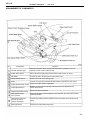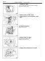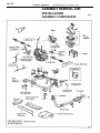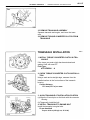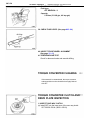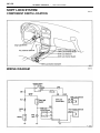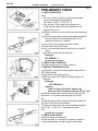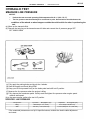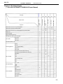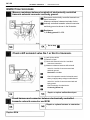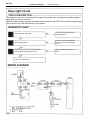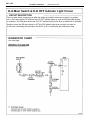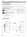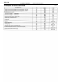
1
AX1–1 AUTOMATIC TRANSAXLE – A140E AUTOMATIC TRANSAXLE AX1–2 AUTOMATIC TRANSAXLE – DESCRIPTION DESCRIPTION PRECAUTIONS When working with FIPG material, you must observe the following. • Using a razor blade and gasket scraper, remove all the old FIPG material from the gasket surfaces. • Thoroughly clean all components to remove all the loose material. • Clean both sealing surfaces with a non–residue solvent. • Apply the FIPG in approx.1 mm (0.04 in.) wide bead along the sealing surface. • Parts must be assembled within 10 minutes of application. Otherwise, the FIPG material must be removed and reapplied. If the vehicle is equipped with a mobile communication system, refer to the precaution in the IN section. GENERAL DESCRIPTION The A140E Electronically Controlled automatic transaxle described in this AX section is a lock– up four–speed automatic transaxle developed exclusively for use with transversely–mounted engines. AX1–3 AUTOMATIC TRANSAXLE – SPECIFICATIONS Type of Transaxle Type of Engine Torque Converter Clutch Stall Torque Ratio Torque Converter Clutch Lock–up Mechanism Gear Ratio Transaxle 2nd Coast Brake (B,) Band Width 1 st Gear 2nd Gear 3rd Gear 0/D Gear Reverse Gear Number of Discs / Plates O/D Direct Clutch (Co) Forward Clutch (C,) Direct Clutch (Ct) 2nd Brake (Bz) 1 st & Reverse Brake (B,) O/D Brake (Bo) mm (in.) ATF Type Capacity liter (US qts, Imp.qts) Total Drain & Refill DESCRIPTION AX1–4 AUTOMATIC TRANSAXLE – OPERATION OPERATION 0 . . . . . Operating Shift lever position Gear Position Parking Reverse Neutral 2nd 3rd O/D 2nd ” 3rd *2nd ’ Down–shift only–no up–shift AX1–5 AUTOMATIC TRANSAXLE – OPERATION 1. FUNCTION OF COMPONENTS COMPONENT FUNCTION O/D Direct Clutch (Co) Connects Overdrive sun gear and overdrive carrier. 0/D Brake (Bo) Prevents overdrive sun gear from turning either clockwise or counterclockwise. O/D One–Clutch (Fo) When transaxle is being driven by engine, connects overdrive sun gear and overdrive carrier. Front Clutch (C1) Connects input shaft and intermediate shaft. Rear Clutch (C2) Connects input shaft and front & rear planetary gear. No. 1 Brake (B1) Prevents front & rear planetary sun gear from turning either clockwise or counterclockwise. No. 2 Brake (B2) Prevents outer race of F, from turning either clockwise or counterclockwise, thus preventing front & rear planetary sun gear from turning counterclockwise. No. 3 Brake (B3) Prevents front planetary carrier from turning either clockwise or counterclockwise. No. 1 One–Way Clutch (F1) When B2 is operating, prevents front & rear planetary sun gear from turning counterclockwise. No. 2 One–Way Clutch (F2) Prevents front planetary carrier from turning counterclockwise. AX1–6 AUTOMATIC TRANSAXLE – OPERATION Power from the engine transmitted to the input shaft via the torque converter clutch is then transmitted to the planetary gears by the operation of the clutch. By operation of the brake and one–way clutch, either the planetary carrier or the planetary sun gear are immobilized, altering the speed of revolution of the planetary gear unit. Shift change is carried out by altering the combination of clutch and brake operation. Each clutch and brake operates by hydraulic pressure. Gear position are decided according to the throttle opening angle and vehicle speed, and shift change automatically occurs. The conditions of operation for each gear position are shown on the following illustrations: AX1–7 AUTOMATIC TRANSAXLE – OPERATION 2. Hydraulic Control System The hydraulic control system is composed of the oil pump, the valve body, the solenoid valves, the accumulator, the clutches and brakes, and the governor valve as well as the fluid passages which connect all of these components. Based on the hydraulic pressure created by the oil pump, the hydraulic control system governs the hydraulic pressure acting on the torque converter clutch, clutches and brakes in accordance with the vehicle driving conditions. There are three solenoid valves on the valve body. The shift solenoid valves No. 1 and No.2 are turned on and off by signals from the ECM to operate the shift valves and change the gear shift position. The No.3 solenoid valve is operated by signals from the ECM to engage or disengage the lock– up clutch of the torque converter clutch. AX1–8 AUTOMATIC TRANSAXLE – OPERATION 3. Electronic Control System The electronic control system for controlling the shift timing and the operation of the lock–up clutch is composed of the following three parts: (a) Sensors: These sense the vehicle speed and throttle position and send this data to the ECM in the form of electronic signals. (b) ECM: This determines the shift and lock–up timing based upon the signals from the sensors. (c) Actuators: Solenoid valves divert hydraulic pressure from one circuit of the hydraulic control unit to another, thus controlling shifting and lock–up timing. SENSORS ECM PATTERN SELECT SWITCH Control of shift timing PARK/NEUTRAL POSITION SWITCH ACTUATORS SHIFT SOLENOID i VALVE NO.1 SHIFT SOLENOID I VALVE NO.2 THROTTLE POSITION SENSOR VEHICLE SPEED SENSOR Control of lock– up timing SHIFT SOLENOID VALVE SL BRAKE LIGHT SWITCH O/D MAIN SWITCH Self–diagnostic system CRUISE CONTROL ECU ENGINE COOLANT TEMPERATURE SENSOR RPM SENSOR Back–up system O/D OFF INDICATOR LIGHT AX1–9 AUTOMATIC TRANSAXLE SYSTEM DIAGRAM – OPERATION AX1–10 AUTOMATIC TRANSAXLE – OPERATION ARRANGEMENT OF COMPONENTS Functions Components No. O/D OFF Indicator Light Blinks and warns the driver, while the 0/D main switch is pushed in, when the electronic control circuit is malfunctioning. Pattern Select Switch Selects the Power mode or the Normal mode for shift and lock–up timing. 0/D Switch Prevents up shift to the O/D gear if the O/D switch is off. Throttle Position Sensor Detects the throttle valve opening angle. ECM Controls the engine and transaxle,actuators based on signals from each sensor. Engine Coolant Temp. Sensor Detects the engine coolant temperature. Vehicle Speed Sensor Detect the vehicle speed. Ordinarily, transaxle control uses signals from the vehicle speed sensor. Park/Neutral Position Switch Detects the shift lever position. Shift Solenoid Valves No.1 and No.2 Control the hydraulic pressure applied to each shift valve, and control the gear shift position and timing. Shift Solenoid Valves SL For lock–up control pressure modulation Controls the hydraulic pressure applied to the lock–up clutch and controls lock–up timing. Stop Light Switch Detects if the brake pedal is depressed. AX1–11 AUTOMATIC TRANSAXLE – PREPARATION PREPARATION SST (SPECIAL SERVICE TOOLS) 09043–38100 Hexagon 10 mm Wrench Remove and install oil pan drain plug. 09308–00010 Oil Seal Puller Remove side gear shaft oil seal. 09350–32014 TOYOTA Automatic Transmission Tool Set (09351–32010) One–way Clutch Test Toot (09351–32020) Stator Stopper (09351–32130) Handle (09351–32150) Oil Seal Replacer 09843–18020 Diagnosis Check Wire 09992–00094 Automatic Transmission Oil Pressure Gauge Set RECOMMENDED TOOLS 09082–00050 TOYOTA Electrical Tester Set Line pressure AX1–12 AUTOMATIC TRANSAXLE – PREPARATION EQUIPMENT Straight edge Check torque converter clutch installation. Vernier calipers Check torque converter clutch installation. Dial indicator or dial indicator with magnetic base Measures drive plate runout. Torque wrench LUBRICANT Item Automatic transaxle fluid (w/o Differential oil) Dry fill Drain and refill Differential oil (w/ Automatic transaxle) Capacity 5.6 liters (5.9 US qts, 4.9 Imp.qts) 2.5 liters (2.6 US qts, 2.2 Imp.qts) 1.6 liters (1.7 US qts, 1.4 Imp. qts) Classification ATF DEXRON ATF DEXRON SSM (SPECIAL SERVICE MATERIALS) 08833–00070 Adhesive 1311, THREE BOND 1311 or equivalent Torque converter clutch mounting bolt AX1–13 AUTOMATIC TRANSAXLE – ON–VEHICLE REPAIR ON–VEHICLE REPAIR VALVE BODY REMOVAL 1. CLEAN TRANSAXLE EXTERIOR To help prevent contamination, clean the exterior of the transaxle. 2. DRAIN TRANSAXLE FLUID Remove the drain plug with SST, and drain the fluid into a suitable container. SST 09043–38100 3. REMOVE OIL PAN AND GASKET NOTICE: Some fluid will remain in the oil pan. Remove all pan bolts, and carefully remove the pan assembly discarding the gasket. 4. EXAMINE PARTICLES IN PAN Remove the magnets and use them to collect any steel chips. Look carefully at the chips and particles in the pan and on the magnet to anticipate what type of wear you will find in the transaxle. Steel (magnetic): bearing, gear and plate wear Brass (non–magnetic): bushing wear 5. REMOVE OIL STRAINER AND APPLY TUBE BRACKET (a) Remove the 3 bolts and the oil strainer. NOTICE: Be careful as oil will come out of the strainer when it is removed. (b) Remove the 2 bolts and the apply tube bracket. 6. DISCONNECT SOLENOID CONNECTORS AX1–14 AUTOMATIC TRANSAXLE – ON–VEHICLE REPAIR 7. REMOVE OIL TUBES Pry up the both tube ends with a large screwdriver and remove the four tubes. 8. REMOVE MANUAL DETENT SPRING 9. REMOVE MANUAL VALVE AND MANUAL VALVE BODY 10. REMOVE VALVE BODY Remove the 12 bolts. 11. REMOVE THROTTLE CABLE (a) Disconnect the throttle cable. (b) Remove the valve body. 12. REMOVE SECOND BRAKE APPLY GASKET AX1–15 AUTOMATIC TRANSAXLE – ON–VEHICLE REPAIR VALVE BODY INSTALLATION 1. INSTALL SECOND BRAKE APPLY GASKET 2. INSTALL VALVE BODY (a) While holding the cam down with your hand, slip the cable and into the slot. (b) Bring valve body into place. NOTICE: Be careful not to entangle the solenoid wire. 3. INSTALL BOLTS IN VALVE BODY Hand tighten the 12 bolts first, then torque with a torque wrench. Torque: 10 N–m (100 kgf–cm, 7 ft–lbf) Bolt length: A 20 mm (0.79 in.) B 25 mm (0.98 in.) C 36 mm (1.42 in.) D50mm(1.97in.) 4. CONNECT SOLENOID WIRING (a) Connect the shift solenoid valve No. 1 connector (white and shorter wire). (b) Connect the shift solenoid valve No. 2 connector (black and longer wire). 5. INSTALL MANUAL VALVE BODY DETENT SPRING (a) Align the manual valve with the pin on the manual shaft lever. (b) Lower the manual valve body into place. (c) Hand tighten the 4 bolts first. Then, tighten them with a torque wrench. Torque: 10 N–m (100 kgf–cm, 7 ft–lbf) AX1–16 AUTOMATIC TRANSAXLE – ON–VEHICLE REPAIR (d) Place the detent spring on the manual valve body and hand tighten the 2 bolts first. Then, tighten them with a torque wrench. Torque: 10 N–m (100 kgf–cm, 7 ft–lbf) (e) Check that the manual valve lever is touching the center of the detent spring tip roller. 6. INSTALL OIL TUBES Tap the tubes with a plastic hammer to install them into the positions indicated in the illustration. NOTICE: Be careful not to bend or damage the tubes. 7. INSTALL OIL STRAINER AND APPLY TUBE BRACK– ET (a) Install the oil strainer and torque the 3 bolts. (b) Install the apply tube bracket and the 2 bolts. Torque: 10 N–m (100 kgf–cm, 7s. ft–lbf) 8. INSTALL MAGNETS IN PAN Install the 2 magnets in the indentations of the pan. 9. INSTALL OIL PAN WITH NEW GASKET NOTICE: Make sure that the magnet does not interfere with the oil tubes. Torque: 4.9 N–m (50 kgf–cm, 43 in.–Ibf) 10. INSTALL DRAIN PLUG WITH NEW GASKET Using SST, install the drain plug with a new gasket and tighten it. Torque: 49 N–m (500 kgf–cm, 36 ft–lbf) SST 09043–38100 AX1–17 AUTOMATIC TRANSAXLE – ON–VEHICLE REPAIR 11. FILL TRANSAXLE WITH ATF Add only about 2 liters of ATF. NOTICE: Do not overfill. Fluid type: ATF DEXRON II 12. CHECK FLUID LEVEL (See page AX1–54) THROTTLE CABLE REMOVAL 1. DISCONNECT THROTTLE CABLE (a) Disconnect the cable housing from the bracket. (b) Disconnect the cable from the throttle linkage. 2. REMOVE PARK/NEUTRAL POSITION SWITCH (a) Remove the clips and, disconnect the transaxle con– trol cable from manual shift lever. (b) Remove the manual shift lever. (c) Remove the park/neutral position switch. 3. REMOVE VALVE BODY (See page AX–13) 4. PULL THROTTLE CABLE OUT OF TRANSAXLE CASE (a) Remove the bolt and retaining plate. (b) Pull the cable out of the transaxle case. AX1–18 AUTOMATIC TRANSAXLE – ON–VEHICLE REPAIR THROTTLE CABLE INSTALLATION 1. INSTALL CABLE IN TRANSAXLE CASE (a) Be sure to push it in all the way. (b) Install the retaining plate and the bolt. 2. INSTALL VALVE BODY (See page AX–15) 3. IF THROTTLE CABLE IS NEW, STAKE STOPPER ON INNER CABLE (a) Bend the cable so there is a radius of about 200 mm (7.87 in.). (b) Pull the inner cable lightly until a slight resistance is felt, and hold it. (c) Stake the stopper 0.8–1.5 mm (0.031–0.059 in.) from the end of outer cable, as shown. 4. CONNECT THROTTLE CABLE (a) Connect the cable to the throttle linkage. (b) Connect the cable housing to the bracket. 5. ADJUST THROTTLE CABLE (See page AX1–55) 6. INSTALL PARK/NEUTRAL POSITION SWITCH (a) Install the park/neutral position switch. (b) Install the manual shift lever. (c) Adjust the park/neutral position switch. (See page AX1–56) (d) Connect the transaxle control cable. AX1–19 AUTOMATIC TRANSAXLE – ON–VEHICLE REPAIR DIFFERENTIAL OIL SEAL REMOVAL 1. REMOVE BOTH DRIVE SHAFTS (See page SA–38) 2. REMOVE BOTH SIDE GEAR SHAFT OIL SEALS Using SST, pull out the oil seal. SST 09308–00010 DIFFERENTIAL OIL SEAL INSTALLATION 1. INSTALL LEFT SIDE GEAR SHAFT OIL SEAL (1) Using SST, drive in a new oil seal. SST 09350–32014 (09351–32130, 08351–32150) Oil seal depth: 2.7 ±0.5 mm (0.11 ±0.02 in.) (2) Coat the lip of oil seal with MP grease. 2. INSTALL RIGHT SIDE GEAR SHAFT OIL SEAL (1) Using SST, drive in a new oil seal. SST 09350–32014 (09351–32130, 09351–32150) Oil seal depth: 0 ± 0.5 mm (0 0.02 in.) (2) Coat the lip of seal with MP grease. 3. INSTALL BOTH DRIVE SHAFTS (See page SA–40) 4. CHECK TRANSAXLE FLUID LEVEL (See page AX1–54) AX1–20 AUTOMATIC TRANSAXLE – ASSEMBLY REMOVAL AND INSTALLATION ASSEMBLY REMOVAL AND INSTALLATION ASSEMBLY COMPONENTS AX1–21 AUTOMATIC TRANSAXLE – ASSEMBLY REMOVAL AND INSTALLATION TRANSAXLE REMOVAL CAUTION: Work must be started after 90 seconds from the time the ignition switch is turned to the ”LOCK” position and the negative (–) terminal cable is discon– nected from the battery. 1. DISCONNECT NEGATIVE (–) TERMINAL CABLE FROM BATTERY 2. REMOVE AIR CLEANER ASSEMBLY 3. REMOVE THROTTLE CABLE FROM ENGINE w/ Cruise Control System: 4. REMOVE CRUISE CONTROL ACTUATOR COVER 5. DISCONNECT CONNECTOR FROM CRUISE CON– TROL ACTUATOR 6. REMOVE GROUND TERMINAL 7. DISCONNECT CONNECTOR FROM VEHICLE SPEED SENSOR AX1–22 AUTOMATIC TRANSAXLE – ASSEMBLY REMOVAL AND INSTALLATION 8. REMOVE STARTER (a) Disconnect the connector and nut. (b) Remove the 2 bolts and the starter. 9. DISCONNECT PARK/NEUTRAL POSITION SWITCH CONNECTOR 10. DISCONNECT SOLENOID CONNECTOR 11. DISCONNECT OIL COOLER HOSE 12. DISCONNECT SHIFT CONTROL CABLE (a) Remove the clip from the control cable. (b) Remove the nut. AX1–23 AUTOMATIC TRANSAXLE – ASSEMBLY REMOVAL AND INSTALLATION 13. REMOVE 2 FRONT SIDE ENGINE MOUNTING BOLT 14. REMOVE 2 BOLT AND CLAMP FROM FRONT FRAME ASSEMBLY 15. REMOVE 3 UPPER TRANSAXLE TO ENGINE BOLT 16. INSTALL ENGINE SUPPORT FIXTURE 17. TIE STEERING GEAR HOUSING TO ENGINE SUP – PORT FIXTURE BY CORD OR EQUIVALENT 18. RAISE AND SUITABLE SUPPORT VEHICLE 19. REMOVE FRONT WHEEL 20. REMOVE EXHAUST PIPE (a) Remove the 3 nuts. AX1–24 AUTOMATIC TRANSAXLE – ASSEMBLY REMOVAL AND INSTALLATION (b) Remove the 2 bolts and nuts from rear exhaust pipe. 21. REMOVE DIFFERENTIAL FLUID DRAIN PLUG AND GASKET 22. DRAIN DIFFERENTIAL FLUID INTO A SUITABLE CONTAINER 23. REMOVE RIGHT AND LEFT ENGINE SIDE COVER NO.2 24. REMOVE ENGINE UNDER FRONT COVER NO.1 AND NO.2 25. REMOVE DRIVE SHAFT (See page SA–38) 26. REMOVE FRONT SIDE ENGINE MOUNTING NUT 27. REMOVE 3 REAR SIDE ENGINE MOUNTING NUTS AX1–25 AUTOMATIC TRANSAXLE – ASSEMBLY REMOVAL AND INSTALLATION 28. REMOVE ENGINE 4 TRANSAXLE MOUNTING BOLTS 29. REMOVE STEERING GEAR HOUSING (a) Remove the 4 bolts and disconnect stabilizer bar bus– hing bracket from the front frame assembly. (b) Remove the 2 bolts and nuts from the steering gear housing. (c) Remove the steering gear housing. 30. REMOVE FRONT FRAME ASSEMBLY (a) Hold the front frame assembly with a jack. (b) Remove the 2 set screws from the right and left fender liners. (c) Remove the 6 bolts and 4 nuts. (d) Remove the front frame assembly. AX1–26 AUTOMATIC TRANSAXLE – ASSEMBLY REMOVAL AND INSTALLATION 31. REMOVE STIFFENER PLATE (a) Hold the transaxle with a jack. (b) Remove the 3 bolts and stiffener plate. 32. REMOVE REAR END PLATE (a) Remove the 4 bolts. (b) Remove the rear end plate. 33. REMOVE TORQUE CONVERTER CLUTCH MOUNT – ING BOLT (a) Turn the crankshaft to gain access to each bolt. (b) Hold the crankshaft pulley nut with a wrench and remove 6 bolts. HINT: First remove dark green colored bolt and then remove the others. 34. REMOVE 3 TRANSAXLE TO ENGINE BOLTS AX1–27 AUTOMATIC TRANSAXLE – ASSEMBLY REMOVAL AND INSTALLATION 35. REMOVE TRANSAXLE ASSEMBLY Separate transaxle and engine, and lower the trans– axle. 36. REMOVE TORQUE CONVERTER CLUTCH FROM TRANSAXLE TRANSAXLE INSTALLATION 1. INSTALL TORQUE CONVERTER CLUTCH IN TRA– NSAXLE If the torque converter clutch has been drained and washed, refill with new ATF. Fluid Type: ATF DEXRON 2. CHECK TORQUE CONVERTER CLUTCH INSTALLA– TION Using a scale and a straight edge, measure from the installed surface to the front surface of the transaxle housing. Correct distance: 13.0 mm (0.51 in.) or more 3. ALIGN TRANSAXLE AT INSTALLATION POSITION (a) Align the 2 knock pins on the block with the converter housing. (b) Temporarily install the bolt. 4. INSTALL TRANSAXLE TO ENGINE BOLT Install the transaxle to engine bolts. 12 mm head bolt Torque: 64 N–m (650 kgf–cm, 47 ft–lbf) AX1–28 AUTOMATIC TRANSAXLE – ASSEMBLY REMOVAL AND INSTALLATION 10 mm head bolt Torque: 46 N–m (470 kgf–cm, 34 ft–lbf) 5. INSTALL TORQUE CONVERTER CLUTCH MOUNT– ING BOLT (a) Clean the threads of the bolts with the gasoline. (b) Coat the threads of the bolts with sealer. Sealer: Part No.08833–00070, THREE BOND 1324 or equi– valent. (c) Tighten the bolts evenly. Torque: 27 N–m (280 kgf–cm, 20 ft–Ibf) HINT: First install dark green colored bolt and then the 5 bolts. 6. INSTALL REAR END PLATE Install the rear end plate with the 4 bolts. 7. INSTALL STIFFENER PLATE (a) Install the stiffener plate with the 3 bolts. (b) Torque the 3 bolts. Torque: 37 N–m (380 kgf–cm, 27 ft–lbf) 8. INSTALL FRONT FRAME ASSEMBLY (a) Hold the front frame assembly with a jack. (b) Install the front frame assembly with the 6 bolts and 4 nuts. (c) Torque the bolts. 19 mm head bolt Torque: 181 N–m (1,850 kgf–cm, 134 ft–lbf) 12 mm head bolt Torque: 32 N–m (330 kgf–cm, 24 ft–lbf) AX1–29 AUTOMATIC TRANSAXLE – ASSEMBLY REMOVAL AND INSTALLATION (d) Torque the nuts. Nut Torque: 36 N–m (370 kgf–cm. 27 ft–lbf) (c) Install the 2 set screws in the right and left fender liners. 9. INSTALL STEERING GEAR HOUSING (a) Install the steering gear housing to the front frame assembly. (b) Install and torque the 2 bolts and nuts. Torque: 181 N–m (1,850 kgf–cm, 134 ft–lbf) (c) Connect the stabilizer bar bushing bracket with the 4 bolts. Torque: 19 N–m (195 kgf–cm, 14 ft–lbf) 10. INSTALL 4 TRANSAXLE MOUNTING BOLTS Torque: 52 N–m (530 kgf–cm, 38 ft–lbf) AX1–30 AUTOMATIC TRANSAXLE – ASSEMBLY REMOVAL AND INSTALLATION 11. INSTALL 3 REAR SIDE ENGINE MOUNTING NUTS Torque: 66 N–m (670 kgf–cm, 48 ft–Ibf) 12. INSTALL FRONT SIDE ENGINE MOUNTING NUT Torque: 80 N–m (820 kgf–cm, 59 ft–lbf) 13. INSTALL DRIVE SHAFT (See page SA–40) 14. INSTALL RIGHT AND LEFT ENGINE SIDE COVER N O.2 15. INSTALL ENGINE UNDER FRONT COVER NO.1 AND NO.2 16. INSTALL DIFFERENTIAL FLUID DRAIN PLUG WITH A NEW GASKET 17. FILL DIFFERENTIAL FLUID Fluid Type: ATF DEXRON ll Capacity: Differential 1.6 liters (1.7 US qts, 1.4 Imp. qts) 18. CHECK DIFFERENTIAL FLUID LEVEL 19. INSTALL EXHAUST PIPE (a) Install and torque the 3 nuts. Torque: 62 N–m (630 kgf–cm, 46 ft–lbf) AX1–31 AUTOMATIC TRANSAXLE – ASSEMBLY REMOVAL AND INSTALLATION (b) Install the rear exhaust pipe with the 2 bolts and nuts. Torque: 103 N–m (1,050 kgf–cm, 76 ft–lbf) 20. INSTALL FRONT WHEEL AND LOWER VEHICLE Torque: 103 N–m (1,050 kgf–cm, 76 ft–lbf) 21. UNTIE STEERING GEAR HOUSING TO ENGINE SUP – PORT FIXTURE BY CORD OR EQUIVALENT 22. REMOVE ENGINE SUPPORT FIXTURE 23. INSTALL 3 UPPER TRANSAXLE TO ENGINE BOLTS Torque: 64 N–m (650 kgf–cm. 47 ft–lbf) 24. INSTALL 2 BOLTS AND CLAMP FROM TO FRAME ASSEMBLY 25. INSTALL 2 FRONT SIDE ENGINE MOUNTING BOLTS Torque: 80 N–m l820 kgf–cm, 59 ft–lbfj AX1–32 AUTOMATIC TRANSAXLE – ASSEMBLY REMOVAL AND INSTALLATION 26. CONNECT SHIFT CONTROL CABLE (a) Install the clip to the control cable. (b) Install the nut. (c) Adjust the control cable. (See page AX1–55) 27. CONNECT OIL COOLER HOSE 28. CONNECT SOLENOID CONNECTOR 29. CONNECT PARK/ NEUTRAL POSITION SWITCH CONNECTOR 30. INSTALL STARTER (a) Install the starter with 2 bolts. Torque: 39 N–m (400 kgf–cm, 29 ft–lbf) (b) Connect the connector and nut. AX1–33 AUTOMATIC TRANSAXLE – ASSEMBLY REMOVAL AND INSTALLATION 31. CONNECT VEHICLE SPEED SENSOR CONNECTOR 32. INSTALL GROUND TERMINAL w/ Cruise Control System: 33. CONNECT CONNECTOR TO CRUISE CONTROL ACTUATOR 34. INSTALL CRUISE CONTROL ACTUATOR COVER 35. INSTALL THROTTLE CABLE TO ENGINE (a) Torque the nuts. Torque: 15 N–m (150 kgf–cm, 11 ft–lbf) (b) Adjust the throttle cable. (See page AX1–55) 36. INSTALL AIR CLEANER ASSEMBLY 37. CONNECT NEGATIVE (–) TERMINAL CABLE TO BATTERY AX1–34 AUTOMATIC TRANSAXLE – ASSEMBLY REMOVAL AND INSTALLATION 38. FILL TRANSAXLE WITH ATF Fluid type: ATF DEXRON II Capacity: 5.6 liters (5.9 US gts, 4.9 Imp.gts) 39. CHECK FLUID LEVEL (See page AX1–64) 40. INSPECT FRONT WHEEL ALIGNMENT (See page SA–40) 41. PERFORM ROAD TEST Check for abnormal noise and smooth shifting. TORQUE CONVERTER CLEANING If the transaxle is contaminated, the torque converter and transmission cooler should be thoroughly flushed with ATF. TORQUE CONVERTER CLUTCH AND DRIVE PLATE INSPECTION 1. INSPECT ONE–WAY CLUTCH (a) Install SST into the inner race of the one–way clutch. SST 09350–33014 (09351–32010) AX1–35 AUTOMATIC TRANSAXLE – ASSEMBLY REMOVAL AND INSTALLATION (b) Install SST so that it fits in the notch of the converter hub and outer race of the one–way clutch. SST 09350–32014 (09351–32020) (c) With the torque converter clutch standing on its side, the clutch locks when turned counterclockwise, and rotates freely and smoothly clockwise. If necessary, clean the converter clutch and retest the clutch. Replace the converter clutch if the clutch still fails the test. 2. MEASURE DRIVE PLATE RUNOUT AND INSPECT RING GEAR Set up a dial indicator and measure the drive plate runout. If runout exceeds 0.20 mm (0.0079 in.) or if the ring gear is damaged, replace the drive plate. If installing a new drive plate, note the orientation of spacers and tighten the bolts. Torque: 83 N–m (850 kgf–cm, 61 ft–lbf) 3. MEASURE TORQUE CONVERTER CLUTCH SLEEVE RUNOUT (a) Temporarily mount the torque converter clutch to the drive plate. Set up a dial indicator. If runout exceeds 0.30 mm (0.0118 in.), try to correct by reorienting the installation of the converter. If ex– cessive runout cannot be corrected, replace the torque converter clutch . HINT: Mark the position of the converter clutch to ensure correct installation. (b) Remove the torque converter clutch. AX1–36 AUTOMATIC TRANSAXLE SHIFT LOCK SYSTEM COMPONENT PARTS LOCATION WIRING DIAGRAM – SHIFT LOCK SYSTEM AX1–37 AUTOMATIC TRANSAXLE – SHIFT LOCK SYSTEM ELECTRIC CONTROL COMPONENTS INSPECTION 1. INSPECT SHIFT LOCK CONTROL ECU Using a voltmeter, measure the voltage at each termi– nals. HINT: Do not disconnect the ECU connector. Connector Terminal Measuring condition Voltage (V) Ignition switch ACC position Ignition switch ON position Depress brake pedal Ignition switch ACC position and P position Ignition switch ACC position and except P position (Approx–after 1 second) Ignition switch ON position and P position Depress brake pedal (Approx–after 20 seconds) Except P position Ignition switch ON, P position and depress brake pedal Shift except P position under conditions above Ignition switch ACC position and P position Shift except P position under condition above 2. INSPECT SHIFT LOCK SOLENOID (a) Disconnect the solenoid connector. (b) Using an ohmmeter, measure the resistance between terminals. Standard resistance: 21–27 (c) Apply the battery positive voltage between terminals. Check that an operation noise can be heard from the solenoid. AX1–38 AUTOMATIC TRANSAXLE – SHIFT LOCK SYSTEM 3. INSPECT KEY INTERLOCK SOLENOID (a) Disconnect the solenoid connector. (b) Using an ohmmeter, measure the resistance between terminals. Standard resistance: 12.5–16.50 (c) Apply the battery positive voltage between terminals. Check that an operation noise can be heard from the solenoid. 4. INSPECT SHIFT LOCK CONTROL SWITCH Inspect that there is continuity between each termi– nal. Terminal Shift Position P position (Release button is not pushed) P position (Release button is pushed) R, N, D, 2, L Position AUTOMATIC TRANSAXLE – TROUBLESHOOTING TROUBLESHOOTING AX1–40 AUTOMATIC TRANSAXLE – TROUBLESHOOTING HOW TO PROCEED WITH TROUBLESHOOTING For troubleshooting using a volt/ohm meter, see page AX1–4042. HOW TO PROCEED WITH TROUBLESHOOTING USING VOLT OHM METER 1. CUSTOMER PROBLEM ANALYSIS Using the customer problem analysis check sheet for reference, ask the customer in as much detail as possible about the problem. 2. CHECK AND CLEAR THE DIAGNOSTIC TROUBLE CODES (PRECHECK) Before confirming the problem symptom, first check the diagnostic trouble code if there are any trouble codes stored in memory. When there are trouble codes, make a note of them, then clear them and proceed to “3. Problem Symptom Confirmation”. 3. PROBLEM SYMPTOM CONFIRMATION Confirm the problem symptoms. 4. SYMPTOM SIMULATION If the problem does not reappear, be sure to simulate the problem by mainly checking the circuits indicated by the diagnostic trouble code in step 2, using “Problem Simulation method”. 5. DIAGNOSTIC TROUBLE CODE CHECK Check the diagnostic trouble codes. Check if there is abnormality in the sensors or the wire harness. If a trouble code is output, proceed to “6. Diagnostic Trouble Code Chart”. If the normal code is output, proceed to “7. Matrix Chart of Problem Symptoms”. Be sure to proceed to “6. Diagnostic Trouble Code Chart” after steps 2 and 3 are completed. If troubleshooting is attempted only by following the trouble code stored in the memory is output, errors could be made in the diagnosis. 6. DIAGNOSTIC TROUBLE CODE CHART If a trouble code is confirmed in the diagnostic trouble code check, proceed to the inspection procedure indicated by the matrix chart for each diagnostic trouble code. 7. PRELIMINARY CHECK Carry out a preliminary check of the transaxle oil level, throttle cable adjustment, etc. 8. SHIFT POSITION SIGNAL CHECK Carry out the shift position signal check when the transaxle gears do not up–shift, down–shift or lock–up. This is to check the signal output condition from the ECM to each solenoid. If the results are NG, then it is likely that the trouble is in the electrical system (particularly in the sensors or the ECM). Proceed to Part 1 (Electrical System) under “ 11. Matrix Chart of Problem Symptoms”. If all the circuits specified in Part 1 are OK, check the ECM and replace it. 9. MECHANICAL SYSTEM TEST (Stall Test, Time Leg Test, Line Pressure Test) If the malfunction is found in the stall test, time lag test or line pressure test, check the parts indicated in the respective tests. 14. MANUAL SHIFTING TEST If the results of the manual driving test are NG, it is likely that the trouble is in the mechanical system or hydraulic system. Proceed to Part 2 (Mechanical System) under the Matrix Chart of Problem Symptoms. AX1–41 AUTOMATIC TRANSAXLE – TROUBLESHOOTING 11. MATRIX CHART OF PROBLEM SYMPTOMS If the normal code is confirmed in the diagnostic trouble code check, perform inspection according to the inspection order in the matrix chart of problem symptoms. Perform diagnosis of each circuit or part in the order shown in the Matrix Chart. The Matrix Chart contains 3 chapters, Electronically Controlled Circuits in Chapter 1, On–vehicle Inspection in Chapter 2 and Off– vehicle Inspection in Chapter 3. If all the circuits indicated in Chapter 1 are normal, proceed to Chapter 2. If all the parts indicated in Chapter 2 are normal, proceed to Chapter 3. If all the circuits and parts in Chapter 1–Chapter 3 are normal and the trouble still occurs, check and replace the ECM. 12. CIRCUIT INSPECTION Perform diagnosis of each circuit in accordance with the inspection order confirmed in steps 6 and 11. Judge whether the cause of the problem is in the sensor, actuators, wire harness and connectors, or the ECM. In some cases, the Flow Chart instructs that a throttle signal check, brake signal check or kick–down signal check (in test mode), be performed. These are diagnosis functions used to check if signals are being input correctly to the ECM. 13. PART INSPECTION Check the individual parts of the mechanical system and hydraulic system in the order of the numbers indicated in the Matrix Chart. 14. REPAIRS After the cause of the problem is located, perform repairs by following the inspection and replacement procedures in this manual or’94 Al 40E AUTOMATIC TRANSAXLE Repair Manual. 15. CONFIRMATION TEST After completing repairs, confirm not only that the malfunction is eliminated, but also conduct a test drive, etc., to make sure the entire electronically controlled transaxle system is operating correctly. AX1–42 AUTOMATIC TRANSAXLE – TROUBLESHOOTING Items inside are titles of pages, in this man– ual, with the page number indicated in the bot– tom portion. See the indicated pages for detailed Customer Problem Analysis explanations. P. AX1–43 Step 2, 5, 12, 15: Diagnostic steps permitting the use of the TOYOTA Check and Clear Diagnostic Trouble. Codes (Precheck) hand–held tester or TOYOTA Precheck) brake–out–box. P. AX1–44–AX1–46 Vehicle Brought to Workshop 1. Symptom does not occur 4. Problem Symptom Confirmation Symptom Simulation P. IN–24 P. AX1–48 Symptom occurs OK Code Preliminary Check Diagnostic Trouble Code Check P.AX–44 AX1–45 NG P. AX1–54 Shift Position Signal Check Diagnostic Trouble Code Chart P. AX1–47 P. AX1–64– OK Mechanical System Tests P. AX1–57 OK 10. Manual Shifting Test P. AX1–63 Matrix Chart of Problem Symptoms– P. AX1–67 Chapter 1 (Electronic) P. AX1–68 12. Circuit Inspection Chapter 2 (On–Vehicle) P. AX1–70 Chapter 3 (OFF–Vehicle) P. AX1–72 13. • Main Throttle Signal Check • Stop Light Signal Check Parts Inspection P.AX1–80 AX1–112 15. Identification of Problem Repair Confirmation Test END AX1–43 AUTOMATIC TRANSAXLE – TROUBLESHOOTING CUSTOMER PROBLEM ANALYSIS AX1–44 AUTOMATIC TRANSAXLE – TROUBLESHOOTING DIAGNOSIS SYSTEM The Electronically Controlled Transaxle has built–in self–diagnostic functions. If the malfunction occurs in the system, the ECM stores the diagnostic trouble code in memory and the O/D OFF (Overdrive OFF) indicator light blinks to inform the driver. The diagnos– tic trouble code stored in memory can be read out by the following procedure. O/D OFF INDICATOR LIGHT INSPECTION 1. Turn the ignition switch to ON. 2. Check if the O/D OFF indicator light lights up when the O/D main switch is pushed out to OFF and goes off when the O/D main switch is pushed in to ON. HINT: • If the O/D OFF indicator light does not light up or stay on all the time, carry out the check for ’O/D OFF Indicator Light Circuit” on page AX–102. • If the O/D OFF indicator light blinks, a trouble code is stored in the ECM memory. DIAGNOSTIC TROUBLE CODE CHECK 1. Turn the ignition switch ON, but do not start the engine. 2. Push in the O/D main switch to ON. HINT: Warning and diagnostic trouble codes can be read only when the O/D main switch is ON. If it is OFF, the 0/D OFF indicator light up will light continu– ously and will not blink. 3. Using SST, connect terminals TE1 and El of the DLC1 or DLC2. SST 09843–18020 AX1–45 AUTOMATIC TRANSAXLE – TROUBLESHOOTING 4: Read the diagnostic trouble code indicated by the number of times the O/D OFF indicator light blinks. HINT: If the system is operating normally, the light will blink 2 times per second. Diagnostic trouble code “42” is shown as an example. HINT: When 2 or more trouble codes are stored in memory, the lower–numbered code is displayed first. If no diagnostic trouble code is output, or if a diagnos– tic trouble code is output even though no diagnostic trouble code output operation is performed, check the TE1 terminal circuit on page AX1–110. DIAGNOSTIC TROUBLE CODE CHECK BY USING TOYOTA HAND–HELD TESTER 1. Hook up the TOYOTA hand–held tester to the DLC2. 2. Read the diagnostic trouble codes by following the prompts on the tester screen. Please refer to the TOYOTA hand–held tester operator’s manual for further details. CANCELLING DIAGNOSTIC TROUBLE CODE After repair of the trouble area, the diagnostic trouble code retained in the ECM memory must be cancelled out by removing the EM fuse for 10 seconds or more, with the ignition switch off. Check that the normal code is output after connecting the fuse. AX1–46 AUTOMATIC TRANSAXLE – TROUBLESHOOTING ECM TERMINALS STANDARD VALUE ECM TERMINAL VALUES MEASUREMENT BY USING TOYOTA BREAK–OUT–BOX AND TOYOTA HAND–HELD TESTER 1. Hook up the TOYOTA break–out–box and TOYOTA hand–held tester to the vehicle. 2. Read the ECM input/output values by following the prompts on the tester screen. HINT: TOYOTA hand–held tester has a “Snapshot” function. This records the measured values and is effective in the diagnosis of intermittent problems. Please refer to the TOYOTA hand–held tester / TOYOTA break–out–box operator’s manual for fur– ther details. AX1–47 AUTOMATIC TRANSAXLE – TROUBLESHOOTING CHECK TERMINAL TT OUTPUT VOLTAGE When a voltmeter is connected to the DLC2, the following items can be checked: 1. Throttle position sensor signal 2. Brake signal 3. Shift position signal 1. VOLTMETER CONNECTION Connect the positive (+) probe of the voltmeter to terminal Tt and the negative (–) probe to terminal E1 of the DLC2. HINT: If a voltmeter with small internal resistance is used, the correct voltage will not be indicated, so use a voltmeter with an internal resistance of at least 10 k . 2. TURN IGNITION SWITCH TO ON (DO NOT START THE ENGINE) 3. CHECK THROTTLE POSITION SENSOR SIGNAL Check if the voltage changes from approximately 0 V to approximately 8 V when the accelerator pedal is gradually depressed from the fully closed position. 4. CHECK BRAKE SIGNAL (LOCK–UP CUT SIGNAL) (a) Open the throttle valve fully to apply approximately 8 V to terminal Tt. (b) In this condition, check terminal Tr voltage when the brake pedal is depressed and released. Tt terminal voltage: 0 V (When brake pedal is depressed) 8 V (When brake pedal is released) 5: START ENGINE 6. CHECK SHIFT POSITION SIGNAL (VEHICLE SPEED ABOVE 10 KM/H OR 6 MPH) Check up–shifting together with terminal TT voltage. HINT: Check for light shocks from up–shifting and for changes in the tachometer. Gear Position Terminal TT output voltage 1 st Gear Below 0.5 V 2nd Gear 1.5–2.6 V 2nd Lock–up 2.5–3.6 V 3rd Gear 3.5–4.6 V 3rd Lock–up 4.5–5.6 V O/D 5.5–6.6 V 0/D Lock–up 6.5–7.6 V If terminal TT output voltage check cannot be perfo– rmed, check TT terminal circuit on page AX1–112. AX1–48 AUTOMATIC TRANSAXLE – TROUBLESHOOTING PROBLEM SYMPTOM CONFIRMATION Taking into consideration the results of the customer problem analysis, try to reproduce the symptoms of the trouble. If the problem is that the transaxle does not up–shift, does not down –shift, or the shift point is too high or too low, conduct the following road test to confirm the automatic shift schedule and simulate the problem symptoms. ROAD TEST NOTICE: Perform the test at normal ATF operating tem– perature 50–80 C (122–176 F). 1. D POSITION TEST Shift into the D position and keep the accelerator pedal constant at the full throttle valve opening posi– tion, and check the following points: (a) Check up–shift operation. Check that 1–2, 2–3 and 3–O/D up–shift takes place, at the shift point shown in the automatic shift schedule. (See page AX1–52) HINT: (1) 0/D Gear Up–shift Prohibition Control. • Coolant temp. is 50C (122F) or less • If there is a 10 km/h (6 mph) difference between the set cruise control speed and vehicle speed. • 0/D main switch is pushed ON (During the O/D OFF indicator light lights up.) (2) 0/D Gear Lock–up Prohibition Control. • Brake pedal is depressed. • Coolant temp. is 50 C (122 F) or less. (b) Check for shift shock and slip. Check for shock and slip at the 1–2, 2–3 and 3–0/ D up–shifts. AX1–50 AUTOMATIC TRANSAXLE – TROUBLESHOOTING (c) Check for abnormal noise and vibration. Run at the D position lock–up or O/D gear and check for abnormal noise and vibration. HINT: The check for the cause of abnormal noise and vibration must be performed very thoroughly as it could also be due to loss of balance in the torque converter clutch, etc. (d) Check kick–down operation. While running in the D position, 2nd, 3rd and O/D gears, check to see that the possible kick–down vehicle speed limits for 2 1, 3 2 and O/D 3 kick–downs conform to those indicated on the auto– matic shift schedule. (See page AX1–52) (e) Check abnormal shock and slip at kick–down. (f) Check the lock–up mechanism. (1) Drive in D position, O/D gear, at a steady speed (lock–up ON) of about 75 km/h (47 mph). (2) Lightly depress the accelerator pedal and check that the RPM does not change abruptly. If there is a big jump in RPM, there is no lock–up. 2. 2 POSITION TEST Shift into the 2 position and, while driving with the accelerator pedal held constantly at the full throttle valve opening position and check on the following points: (a) Check up–shift operation Check to see that the 1 2 up–shift takes place and that the shift point conforms to the automatic shift schedule. (See page AX1–52) HINT: There is no O/D up–shift and lock–up in the 2 position. AX1–51 AUTOMATIC TRANSAXLE – TROUBLESHOOTING (b) Check engine braking. While running in the 2 position and 2nd gear, release the accelerator pedal and check the engine braking effect. (c) Check for abnormal noises during acceleration and deceleration, and for shock at up–shift and down– shift. 3. L POSITION TEST Shift into the L position and while driving with the accelerator pedal held constantly at the full throttle valve opening position, and check the following points: (a) Check no up–shift. While running in the L position, check that there is no up–shift to 2nd gear. (b) Check engine braking. While running in the L position, release the accelera– tor pedal and check the engine braking effect. (c) Check for abnormal noises during acceleration and deceleration. AX1–52 AUTOMATIC TRANSAXLE – TROUBLESHOOTING 4. R POSITION TEST Shift into the R position and while starting at full throttle, check for slipping. CAUTION: Before conducting this rest ensure that the test area is free from personnel and obstructions. 5. P POSITION TEST Stop the vehicle on a gradient (more than 5 ) and after shifting into the P position, release the parking brake. Then check to see that the parking lock pawl holds the vehicle in place. AX1–52 AUTOMATIC TRANSAXLE – TROUBLESHOOTING AUTOMATIC SHIFT SCHEDULE SHIFT POINT NORM Mode Shift position Shifting point Vehicle speed km/h (mph) Shifting point Vehicle speed km/h (mph) D position 2 position L position PWR Mode Shift position D position 2 position L position AX1–53 AUTOMATIC TRANSAXLE – TROUBLESHOOTING LOCK–UP POINT NORM Mode D position Throttle valve opening 596 Lock–up ON km/h (mph) Lock–up OFF km/h (mph) Lock–up ON km/h (mph) Lock–up OFF km/h (mph) 3rd Gear O/D Gear PWR Mode D position Throttle valve opening 596 3rd Gear O/D Gear *O/D main switch OFF HINT: (1) In the 2 and L positions, all stages lock–up is OFF. (2) In the following cases, the lock–up will be released regardless of the lock–up pattern. • When the throttle valve is completely closed. • When the brake light switch is ON. AX1–54 AUTOMATIC TRANSAXLE – TROUBLESHOOTING PRELIMINARY CHECK 1. CHECK FLUID LEVEL HINT: • Drive the vehicle so that the engine and transaxle are at normal operating temperature. Fluid temp.: 70–80 C (158–176 F) • Only use the COOL range on the dipstick as a rough reference when the fluid is replaced or the engine does not run. (a) Park the vehicle on a level surface and set the parking brake. (b) With the engine idling and the brake pedal depressed, shift the shift lever into all positions from P to L position and return to P position. (c) Pull out the oil level gauge and wipe it clean. (d) Push it back fully into the tube. (e) Pull it out and check that–the fluid level is in the HOT range. If the level is at the low side, add fluid. Fluid type: ATF DEXRON II NOTICE: Do not overfill. 2. CHECK FLUID CONDITION If the fluid smells burnt or is black, replace it. 3. REPLACE TRANSAXLE FLUID (a) Using SST, remove the drain plug and drain the fluid. SST 09043–38100 (b) Reinstall the drain plug securely. (c) With the engine OFF, add new fluid through the oil filler tube. Fluid type: ATF DEXRON^II Capacity: Total: 5.6 liters (5.9 US qts, 4.9 Imp. qts) Drain and refill: 2.5 liters (2.6 US qts. 2.2 Imp. qts) (d) Start the engine and shift the shift lever into all posi– tions from P to L position and then shift into P posi– tion. (e) With the engine idling, check the fluid level. Add fluid up to the COOL level on the dipstick. (f) Check the fluid level at the normal operating tempera– ture 70–80 C (158–176 F) and add as neces– sary. NOTICE: Do not overfill. 4. CHECK FLUID LEAKS Check for leaks in the transaxle. If there are leaks, it is necessary to repair or replace O –rings, seal packings, oil seals, plugs or other parts. AX1–55 AUTOMATIC TRANSAXLE – TROUBLESHOOTING 5. INSPECT AND ADJUST THROTTLE CABLE (a) Check that the throttle valve is fully closed. (b) Check that the inner cable is not slack. (c) Measure the distance between the outer cable end and stopper on the cable. Standard distance: 0–1 mm (0–0.04 in.) If the distance is not standard, adjust the cable by the adjusting nuts. 6. INSPECT AND ADJUST SHIFT CABLE When shifting the shift lever from the N position to other positions, check that the lever can be shifted smoothly and accurately to each position and that the position indicator correctly indicates the position. If the indicator is not aligned with the correct position, carry out the following adjustment procedures: (a) Loosen the swivel nut on the manual shaft lever. (b) Push the manual shaft lever fully toward the right side of the vehicle. (c) Return the control shaft lever 2 notches to U position. (d) Set the shift lever to N position. (e) While holding the shift lever lightly toward the R position side, tighten the shift lever nut. AX1–56 AUTOMATIC TRANSAXLE – TROUBLESHOOTING 7. INSPECT AND ADJUST PARK/NEUTRAL POSITION SWITCH Check that the engine can be started with the shift lever only in the N or P position, but not in other positions. If not as started above, carry out the following adjust– ment procedure: (a) Loosen the park/neutral position switch bolt and set the shift lever to the N position. (b) Align the groove and neutral basic line. (c) Hold in position and tighten the bolt. Torque: 5.4 N–m (55 kgf–cm, 48 in.¿lbf) 8. INSPECT IDLE SPEED (N POSITION) Idle speed: 750 rpm (In N position and air conditioner OFF) AX1–57 AUTOMATIC TRANSAXLE – TROUBLESHOOTING MECHANICAL SYSTEM TESTS STALL TEST The object of this test is to check the overall performance of the transaxle and engine by measuring the stall speeds in the D and R positions. NOTICE: • Perform the test at normal operating fluid temperature 50–80 C (122–176 F). • Do not continuously run this test longer than 5 seconds. • To ensure safety, conduct this test in a wide, clear, level area which provides good traction. • The stall test should always be carried out in pairs. One technician should observe the conditions of the wheels or wheel stoppers outside the vehicle while the other is performing the test. MEASURE STALL SPEED (a) Chock the 4 wheels. (b) Connect a tachometer to the engine. (c) Fully apply the parking brake. (d) Keep your left foot pressed firmly on the brake pedal. (e) Start the engine. (f) Shift into the D position. Fully depress the accelerator pedal with your right foot. Quickly read the stall speed. Stall speed: 2,450 ±150 rpm (g) Perform the same test in R position. Quickly read the stall speed. Stall speed: 2,450 ±150 rpm AX1–58 AUTOMATIC TRANSAXLE – TROUBLESHOOTING EVALUATION Possible cause Problem • Engine output may be insufficient. • Stator one–way clutch is operating properly (a) Stall speed low in D and R positions. (b) Stall speed high in D position. (c) Stall speed high in R position. (d) Stall speed high in D and R position. HINT: If more than 600 rpm below the specified value, the torque converter clutch could be faulty. • • • • Line pressure too low Forward clutch slipping No.2 one–way clutch not operating properly 4/D one–way clutch not operating properly • • • • Line pressure too low Direct clutch slipping First and reverse brake slipping O/D clutch slipping • Line pressure too low • Improper fluid level • 0/D one–way clutch not operating properly AX1–59 AUTOMATIC TRANSAXLE – TROUBLESHOOTING TIME LAG TEST When the shift lever is shifted while the engine is idling, there will be a certain time lapse or lag before the shock can be felt. This is used for checking the condition of the 4/D direct clutch, forward clutch, direct clutch, and first and reverse brake. NOTICE: • Perform the test at normal operating fluid temperature 50–80 C (122–176 F). • Be sure to allow a one minute Interval between tests. • Make 3 measurements and take the average value. • MEASURE TIME LAG (a) Fully apply the parking brake (b) Start the engine and check idle speed. Idle speed: 750 rpm (in N position and air conditioner OFF) (c) Shift the shift lever from N to D position. Using a stop watch, measure the time it takes from shifting the lever until the shock is felt. In same manner, measure the time lag for N–R. Time lag: ND Less than 1.2 seconds NR Less than 1 .5 seconds AX1–60 AUTOMATIC TRANSAXLE – TROUBLESHOOTING EVALUATION If ND or NR time lag are longer than specified: Possible cause Problem ND time lag is longer • Line pressure too low • Forward clutch worn • O/D one–way clutch not operating properly NR time lag is longer • • • • Line pressure too low Direct clutch worn First and reverse brake worn O/D clutch worn AX1–61 AUTOMATIC TRANSAXLE – TROUBLESHOOTING HYDRAULIC TEST MEASURE LINE PRESSURE NOTICE: • Perform the test at normal operating fluid temperature 50–80 C (122–176 F). • The line, pressure test should always be carried out in pairs. One technician should observe the conditions of the wheels or wheel stoppers outside the vehicle while the other is performing the test. (a) Warm up the transaxle fluid. (b) Remove the test plug on the transaxle case left side and connect the oil pressure gauge SST. SST 09992–00094 (c) Fully apply the parking brake and chock the 4 wheels. (d) Start the engine and check idling RPM. (e) Keep your left foot pressed firmly on the brake pedal and shift into D position. (f)’ Measure the line pressure when the engine is idling. (g) Fully depress the accelerator pedal. Quickly read the highest line pressure when engine speed reaches stall speed. (h) In the same manner, perform the test in R position. SPECIFIED LINE PRESSURE Line pressure Idling Stall D position kPa (kgf/emt, psi) R position kPa (kgf/cmt, psi) 362–422 (3.7–4.3, 53–61) 618–794 (6.3–8.1,90–115) 750–897 (7.7–9.2,109–130) 1,373–1,608 (14.0–16.4,199–233) If the measured pressures are not up to specified values, recheck the throttle cable adjustment and retest. AX1–62 AUTOMATIC TRANSAXLE – TROUBLESHOOTING EVALUATION Possible cause Problem If the measured values at all positions are higher. If the measured values at all positions are lower. If pressure is low in the D position only. If pressure is low in the R position only. • • • • • • • • • • • • • Throttle cable out of adjustment Throttle valve defective Regulator valve defective Throttle cable out of adjustment Throttle valve defective Regulator valve defective Oil pump defective O/D direct clutch defective D position circuit fluid leakage Forward clutch defective R position circuit fluid leakage Direct clutch defective First and reverse brake defective AX1–63 AUTOMATIC TRANSAXLE – TROUBLESHOOTING MANUAL SHIFTING TEST HINT: With this test, it can be determined whether the trouble is within the electrical circuit or is a mechani– cal problem in the transaxle. 1. DISCONNECT SOLENOID WIRE 2. INSPECT MANUAL DRIVING OPERATION Check that the shift and gear positions correspond with the table below. Shift Position Gear Position D Position O/D 2 Position 3rd L Position R Position Reverse P Position Pawl Lock HINT: If the L, 2 and D position gear positions are difficult to distinguish, perform the following road test. • While driving, shift through the L, 2 and D positions. Check that the gear change corresponds to the shift position. If any abnormality is found in the above test, the problem is in the transaxfe itself. 3. CONNECT SOLENOID WIRE 4. CANCEL OUT DIAGNOSTIC TROUBLE CODE (See page AX1–45) AUTOMATIC TRANSAXLE -Memo – TROUBLESHOOTING AUTOMATIC TRANSAXLE -Memo – TROUBLESHOOTING AX1–66 AUTOMATIC TRANSAXLE – TROUBLESHOOTING STANDARD VALUE OF ECM TERMINAL ECM Terminals Symbols Condition Wiring Color Standard Value IG OFF IG ON Vehicle driving in 2nd gear position IG OFF • G ON Vehicle driving in 2nd gear position IG OFF IG ON Vehicle driving under lock–up position IG ON IG ON IG ON • G ON lG ON Pattern select SW: PWR Pattern select SW: NORM Brake pedal is depressed Brake pedal is released Engine Coolant temp. 80C (1 76T) Accel. pedal is released Accel. pedal is depressed Accel. pedal is released Accel. pedal is depressed tG ON IG ON OD main SW: ON OD main SW: OFF IG ON Disconnect following connectors: • Cruise control ECU P or N position IG ON P and N position IG ON 2 position Except 2 position lG ON L position Except L position Standing still Turn one front wheel slowly. AX1–67 AUTOMATIC TRANSAXLE – TROUBLESHOOTING MATRIX CHART OF PROBLEM SYMPTOMS If a normal code is displayed during the diagnostic trouble code check but the trouble still occurs, check the circuits for each symptom in the order given in the charts on the following pages and proceed to the page given for troubleshooting. The Matrix Chart is divided into 3 chapters. Chapter 1: Electronic Circuit Matrix Chart Chapter 2: On–vehicle Repair Matrix Chart Chapter 3: Off–vehicle Repair Matrix Chart When troubleshooting, check Chapter 1 first. If instructions are given in Chapter 1 to proceed to Chapter 2 or 3, proceed as instructed. 1. If the instruction “Proceed to next circuit inspection shown on matrix chart” is given in the flow chart for each circuit, proceed to the circuit with the next highest number in the table to continue the check. 2. If the trouble still occurs even though there are no abnormalities in any of the other circuits, then check or replace the ECM. AX1–68 AUTOMATIC TRANSAXLE – TROUBLESHOOTING Vehicle does not move in any forward position and reverse position Vehicle does not move in a particular position or positions 1 st ± 2nd No up–shift 2nd¿¿ 3rd 3rd O/D 0 / D3rd No down–shift 3rd 2nd 2nd 1 st No lock–up No lock–up off Shift point too high or *too low Up–shifts to 2nd while in L position Up–shifts to 3rd while in L position Up–shifts to O/D from 3rd while O/D switch is OFF Up–shifts to O/D from 3rd while engine is cold ND Harsh engagement Lock–up Any driving position Forward and reverse Slip or Shudder Particular position No engine braking Poor acceleration No–kick–down No pattern select Large shift shock or engine stalls when starting off or stopping. EG–396 AX1–92 AX1–96 IDL switch circuit Park/neutral position switch circuit Stop light circuit AX1–88 Shift solenoid valve SL circuit Symptom AX1–90 AX1–84 Shift solenoid valve No.1, No.2 circuit Suspect Area Throttle position sensor circuit AX1–80 See page Vehicle speed sensor circuit Chapter 1. Electronic Circuit AX1–70 AX1–72 OFF–Vehicle repair matrix chart EG–318 EG–356 On–Vehicle repair matrix chart ECM Engine coolant temperature sensor circuit AX1–108 AX1–102 O/D switch and O/D OFF indicator switch circuit O/D cancel signal circuit AX1–98 Pattern select switch circuit AUTOMATIC TRANSAXLE – TROUBLESHOOTING AX1–69 AX1–70 AUTOMATIC TRANSAXLE – TROUBLESHOOTING Vehicle does not move in R position Vehicle does not move in any forward position or reverse position No lock–up No lock–up OFF No kick–down No engine braking 2nd 1st 2nd No up–shift 3rd 2nd 3rd O/D O/D 3rd No down–shift 3rd2nd 2nd1st NR ND NL 1 st2nd (D position 1 st2nd (2 position) Harsh engagement 1 st2nd3rd 1st2nd3rdO/D 2nd3rd 3rdO/D O/D3rd 3rd2nd Sliper shudder in forward and reverse (Directry after E/G start) C2 accumulator B2 accumulator. C, accumulator 3–4 shift valve 2–3 shift valve 1–2 shift valve Symptom Oil strainer Suspect Area Manual valve See page AX1–13 Chapter 2. On–Vehicle Repair (*:’94 A140E AUTOMATIC TRANSAXLE Repair Manual) OFF–vehicle repair matrix chart AX1–72 – Primary regulator valve Cut back valve Throttle valve Lock–up relay valve Throttle modulator valve 2nd modulator valve Low modulator valve Accumulator control valve Co accumulator Bo accumulator AUTOMATIC TRANSAXLE TROUBLESHOOTING AX1–71 AX1–72 AUTOMATIC TRANSAXLE – TROUBLESHOOTING Vehicle does not move in any forward position Vehicle does not move in reverse position Vehicle does not move in any forward position and reverse position No lock–up No lock–up OFF Large shock during lock–up E/G stalls when starting off and stopping 1 st2nd No up–shift 2nd3rd 3rd ± O/D No down shift 2nd1 st NR N D Harsh engagement 1 st 2nd (D position) 2nd3rd 3rd O/D Forward and reverse (After warm–up) Forward and reverse (Directly after E/G start) R position 1 St Slip or shudder 2nd 2nd 3rd (Up–shift 3rd O/D 1 st 3rd No engine braking 2nd All positions O/D Other than O/D Poor acceleration Other than 2nd 1st and 2nd 1st and R position R position Bo O/D brake C, Direct clutch C, Forward clutch Co O/D direct clutch Symptom Parking lock pawl Suspect Area Torque converter clutch See page AX1–34 Chapter 3. Off–Vehicle Repair (*:’94 A140E AUTOMATIC TRANSAXLE Repair Manual) Rear planetary gear Front planetary gear O/D planetary gear F2 No.2 one–way clutch F, No.1 one–way clutch FO O/D one–way clutch B2 Second brake B31 st and reverse brake B, 2nd coast brake AUTOMATIC TRANSAXLE – TROUBLESHOOTING AX1–73 AX1–74 AUTOMATIC TRANSAXLE – LOCATION OF CONNECTORS Location of Connectors in Engine Compartment TROUBLESHOOTING AX1–75 AUTOMATIC TRANSAXLE Location of Connectors in Body Sedan Coupe – TROUBLESHOOTING AX1–76 AUTOMATIC TRANSAXLE Wagon – TROUBLESHOOTING AX1–77 AUTOMATIC TRANSAXLE Location of Connectors in Instrument Panel – TROUBLESHOOTING AX1–78 AUTOMATIC TRANSAXLE – TROUBLESHOOTING AX1–79 AUTOMATIC TRANSAXLE J/B No–1 J/B No.3 – TROUBLESHOOTING AX1–80 AUTOMATIC TRANSAXLE – TROUBLESHOOTING CIRCUIT INSPECTION Diag. Trouble Code 42 No.1 Vehicle Speed Sensor Circuit CIRCUIT DESCRIPTION The No. 1 vehicle speed sensor outputs a 4–pulse signal for every revolution of the differential case. After this signal has been converted into a more precise rectangular waveform by the waveform shaping circuit inside the combination meter, it is then transmitted to the ECM. DTC No. Diagnostic Trouble Code Detection Condition If the vehicle speed sensor signal is not input for 2 seconds or longer after condition A or B (described below) occurs, DTC 42 is recorded and the OD OFF indicator light lights up simultaneously. CONDITION A • 30 seconds or more elapses after the park/ neutral position switch goes OFF. • The throttle opening ratio and engine RPM are within the shadded area. Trouble Area • • • • Vehicle speed sensor Combination meter Harness or connector between vehicle speed sensor and ECM ECM CONDITION B Throttle Opening Ratio • 1 second or more elapses after the park/neutral position switch goes OFF. • A vehicle speed sensor signal of 14 km/h ($.7 mph) or more was input. • The stop light switch is OFF (brake pedal is released). voi 547 • Waveform between terminals SPD and E1 when vehicle speed is approx. 20 km/h (12 MPH). HINT: The greater the vehicle speed, the greater the number of vehicle speed sensor signals produced. AX1–81 AUTOMATIC TRANSAXLE – TROUBLESHOOTING CIRCUIT DESCRIPTION Fail Safe Function If the vehicle speed sensor fails, shift control takes place so that the throttle opening ratio and RPM are controlled according to the shift control map. DIAGNOSTIC CHART 5 V Fixed Measure voltage between terminal SPD of combination meter connector and body ground. 0 V Fixed Check speedometer circuit. See combination meter troubleshooting on B E section. Changes 0VH5V Replace ECM. Measure voltage between terminals SPD and E1 of ECM connector. Check and repair harness or connector between combination meter and ECM. WIRING DIAGRAM Replace–ECM. AX1–82 AUTOMATIC TRANSAXLE – TROUBLESHOOTING INSPECTION PROCEDURE Measure voltage between terminal S P D of combination meter connector and body ground. (a) Shift the shift lever to N position. (b) Jack up one of the front wheels. (c) Disconnect the cruise control ECU and PPS connectors. (d) Turn IG switch ON. Measure voltage between terminal SPD of com– bination meter connector and body ground when slowly turning the Jack up wheel. Voltage: Constantly 0 V...... Go to Next Step Constantly 4–6 V...... Go to NG 1 Changes 0 V H 4 H 6 V ..... Go to N G 2 NG1 Check combination meter circuit. See combination meter troubleshooting. NG2 Replace ECM. Measure voltage between terminals SPD and E, of ECM. (1) Disconnect combination meter and cruise control ECU connectors. (2) Turn IG switch ON. (3) Measure voltage between terminals SPD and E, of ECM connector. Voltage: 4–6 V Replace ECM. Check and repair harness or connector between com bination meter and ECM. AUTOMATIC TRANSAXLE -Memo – TROUBLESHOOTING AX1–84 AUTOMATIC TRANSAXLE – TROUBLESHOOTING Diag. Trouble Code 62 63 Shift Solenoid Valve No–1 and No.2 Circuit CIRCUIT DESCRIPTION Shifting from 1 st to O/D is performed in combination with ON and OFF of the shift solenoid valves No.1 and No.2 controlled by the ECM. If an open or short circuit occurs in either of the solenoid valves, the ECM controls the remaining normal solenoid to allow the vehicle to be operated smoothly (Fail safe function). Fail Safe Function If either of the solenoid valve circuits develops a short or an open, the ECM turns the other solenoid ON and OFF to shift to the gear positions shown in the table below. The ECM also turns the lock–up solenoid valve OFF at this time. If both solenoids malfunction, hydraulic control cannot be performed electronically and must be done manually. Manual shifting as shown in the following table must be done. (in the case of a short circuit, the ECM stops sending current to the short circuited solenoid). SOLENOID VALVE NO.1 MALFUNCTIONING NORMAL Position Solenoid valve No. 1 No. 2 Gear Solenoid valve No. 1 OFF OFF No. 1 Gear No.2 BOTH SOLENOID VALVES MALFUNCTIONING Gear when shift selector is manually operated 3rd 2nd 3rd 3rd O/D OFF OFF O/D OFF O/D O/D 3rd OFF O/D O/D O/D OFF O/D O/D 3rd OFF 3rd 3rd 3rd OFF 3rd 3 rd 3rd 2nd OFF Solenoid valve No. 2 OFF OFF Gear SOLENOID VALVE N0.2 MALFUNCTIONING 3rd OFF 3rd OFF 2nd 2nd x : Malfunctions Check the shift solenoid valve No.1 when diagnostic trouble code 62 is output and check the shift solenoid valve No.2 when diagnostic trouble code 63 is output. Code No. 62,63 Diag. Trouble Code Detection Condition (a) Solenoid resistance is 8 or lower (short circuit) when solenoid is energized. (b) Solenoid resistance is 100 k or higher (open circuit) when solenoid is not energized. The ECM checks for an open or short circuit in the shift solenoid valve No–1 and No.2 circuit when it changes gear position. The ECM records diag. trouble code 62 or 63 if condi tion (a) or (b) is detected once, but it does not blink the O/D OFF indicator light. After the ECM detects condition (a) or (b) con– tinuously 8 times or more, it cancels the O/D OFF indi cator light to blink until condition (a) or (b) disappears After that, if the ECM detects condition (a) or (b) once, it starts blinking the O/D OFF indi– cator light again. Trouble area • • • Shift solenoid valve No.1 or No.2 Harness or connector between shift solenoid valve No.1 or No.2 and ECM connector ECM AX1–85 AUTOMATIC TRANSAXLE – TROUBLESHOOTING DIAGNOSTIC CHART Measure resistance between .terminals of electronically controlled transaxle solenoid connector and body ground. Check shift solenoid valve No.1 or No.2 in transaxle. Repair or replace malfunctioned part. Check harness and connector between electronically controlled transaxle solenoid connector and ECM. Repair or replace harness or con– nector. Replace ECM. WIRING DIAGRAM AX1–86 AUTOMATIC TRANSAXLE – TROUBLESHOOTING INSPECT ION PROCEDURE Measure resistance between terminals of electronically controlled transaxle solenoid connector and body ground. Disconnect electronically controlled transaxle so– lenoid connector. Measure resistance between terminals of elec– tronically controlled transaxle solenoid connector and body ground as shown in the illustration. Resistance: 1, 2–Body ground 11–15 0 Go to step Check shift solenoid valve No.1 or No.2 in transaxle. (1) Jack up the vehicle. (2) Remove oil pan. (1) Check shift solenoid valve No.1 and No.2 connector connection. (2) Measure resistance between shift solenoid valve No.1 and No.2 connector terminals and body ground. Resistance: 11–15 Check for operation sound of solenoids sound when you apply battery voltage to shift solenoid valve No.1 and No.2 connector terminals and body ground. Check continuity of solenoid wire. Continuity (Below 1) Repair or replace malfunctioned part. Check harness and connector between electronically controlled transaxle solenoid connector and ECM. Repair or replace harness or connector. Replace ECM. AUTOMATIC TRANSAXLE -Memo – TROUBLESHOOTING AX1–88 AUTOMATIC TRANSAXLE – TROUBLESHOOTING Diag. Trouble Code 64 Shift Solenoid Valve SL Circuit CIRCUIT DESCRIPTION The shift solenoid valve SL is turned ON and OFF by signals from the ECM to control the hydraulic pressure acting on the lock–up relay valve, which then controls operation of the lock–up clutch. If a malfunction occurs in this circuit and diagnostic trouble code 64 is stored in memory, the O/D OFF indicator light does not blink. Fail Safe Function If the ECM detects a malfunction, it turns the lock–up solenoid valve OFF. Code No. Diag. Trouble Code Detection Condition (a) Solenoid resistance is 8 or lower (short circuit) when solenoid energized. (b) Solenoid resistance is 100 k or higher (open circuit) when solenoid is not energized. ECM memorizes diag. trouble code 64 if above (a) or (b) condition is detected once or more, but ECM does not start O/D OFF indicator light blinking. Trouble area • • • Shift solenoid valve SL Harness or connector between shift solenoid valve SL and ECM ECM DIAGNOSTIC CHART Check shift solenoid valve SL. Repair or replace malfunctioned part. Check harness and connector between electronically controlled transaxle solenoid connector and ECM. Repair or replace harness or connector. Replace ECM. WIRING DIAGRAM AX1–89 AUTOMATIC TRANSAXLE – TROUBLESHOOTING INSPECTION PROCEDURE Check shift solenoid valve SL. (1) Check shift solenoid valve SL connector connection. (2) Measure resistance between shift solenoid valve SL connector terminals and body ground. Resistance: 11–15 Check that shift solenoid valve SL makes opera– tion sound when apply battery voltage shift so– lenoid valve SL connector terminal and body ground. Check continuity of solenoid wire. Continuity (Below 1) Repair or replace malfunctioned part. Check harness and connector between electronically controlled transaxle solenoid connector–and ECM. Repair or replace harness or connector. Replace ECM. AX1–90 AUTOMATIC TRANSAXLE – TROUBLESHOOTING Throttle Position Sensor Circuit CIRCUIT DESCRIPTION. The throttle position sensor detects the throttle valve opening angle and sends signals to the ECM. DIAGNOSTIC CHART Throttle position signal check. Proceed to next circuit inspection shown on matrix chart (See page AX1–68). Check throttle position sensor. Replace throttle position sensor. Check harness and connector between ECM and throttle position sensor (See page IN–31). Repair or replace harness or con– nector. Check and replace ECM. WIRING DIAGRAM AX1–91 AUTOMATIC TRANSAXLE – TROUBLESHOOTING INSPECTION PROCEDURE Throttle position signal check. Turn ignition switch ON (Do not start the engine). Check voltage at terminal TT of the DLC2 while gradually depressing the accelerator pedal from the fully closed position to the fully opened position. Voltage changes from 0 V to 8 V by stages. Do not depress the brake pedal during this test. The voltage will stay at 0 V if it is depressed. Proceed to next circuit inspection shown on matrix chart (See page AX1–68). Check throttle position sensor. See engine troubleshooting section on page EG–376. Replace throttle position sensor. Check harness and connector between ECM and throttle position sensor (See page IN–31). Repair or replace harness or connector. Check and replace ECM. AX1–92 AUTOMATIC TRANSAXLE – TROUBLESHOOTING Park Neutral Position Switch Circuit CIRCUIT DESCRIPTION The park/neutral position switch detects the shift lever position and sends signals to the ECM. The ECM receives signals (NSW, 2 and L) from the park/neutral position switch. When the signal is not sent to the ECM from the park/neutral position switch, the ECM judges that the shift lever is in the D position. DIAGNOSTIC CHART Check voltage between terminals NSW, 2, L of ECM connector and body ground. Proceed to next circuit inspection shown on matrix chart (See page AX1–68). Check park/neutral position switch. Replace park/neutral position switch. Check harness and connector between ECM and park/neutral position switch, park/neutral position switch and battery (See page IN–31). Repair or replace harness or con– nector. Check and replace ECM. AX1–93 AUTOMATIC TRANSAXLE WIRING DIAGRAM – TROUBLESHOOTING AX1–94 AUTOMATIC TRANSAXLE – TROUBLESHOOTING INSPECTION PROCEDURE Check voltage between terminals NSW, 2, L of ECM connector and body ground. Turn ignition switch ON. Measure voltage between terminals NSW, 2, L of ECM connector and body ground when the shift lever is put in the following positions. Position P, N NSW–body ground Below 1 V 10–14 V* 2–body ground Below 1 V L–body ground Below 1 V Below 1 V Below 1 V 10–14 V Below 1 V Below 1 V 10–14 V 10–14V Below 1 V 10–14 V Below 1 V 10–14 V *: The voltage will drop slightly due to lighting up of the back up light. Proceed to next circuit inspection shown on matrix chart (See page AX1–68). Check park/neutral position switch. Remove park/neutral position switch. Check continuity between each terminal shown be– low when the shift lever is put in each position. Continuity Terminal Shift Position Replace park/neutral position switch. Check harness and connector between ECM and park/neutral position switch, park/neutral position switch and battery (See page IN–31). Repair or replace harness or connector. Check and replace ECM. AUTOMATIC TRANSAXLE -Memo – TROUBLESHOOTING AX1–96 AUTOMATIC TRANSAXLE – TROUBLESHOOTING Stop Light Circuit CIRCUIT DESCRIPTION The purpose of this circuit is to prevent the engine from stalling when the brakes are suddenly applied while driving in lock–up condition. When the brake pedal is operated, this switch sends a signal to the ECM. Then the ECM cancels opera– tion of the lock–up clutch while braking is in progress. DIAGNOSTIC CHART Check operation of stop light. Check and repair stop light circuit (See page BE–62). Check stop light signal. Proceed to next circuit inspection shown on matrix chart (See page AX1–50). Check harness and connector between ECM and stop light switch (See page IN–31) . Repair or replace harness of con– nector. Check and replace ECM. WIRING DIAGRAM AX1–97 AUTOMATIC TRANSAXLE – TROUBLESHOOTING INSPECTION PROCEDURE Check operation of stop light. Check if the stop light goes on and off normally when the brake pedal is depressed and released . Check and repair stop light circuit (See page BE–50) Check stop light signal. (1) Connect voltmeter to terminals TT and E l of the DLC2. (2) Turn ignition switch ON (Do not start the engine). (3) Fully depress the accelerator pedal until the voltmeter indicates 8 v and hold it. (4) Depress and release the brake pedal and check the voltage. Brake pedal Voltage Depressed Released Proceed to next circuit inspection shown on matrix chart (See page AX1–68). Check harness and connector between ECM and stop light switch (See page IN–31). Repair or replace harness or connector. Check and replace ECM. AX1–98 AUTOMATIC TRANSAXLE – TROUBLESHOOTING Pattern Select Switch Circuit The ECM has stored in its memory the gear shift patterns for D position, 2nd position and L position, and also the lock–up pattern for D position. Two types of gear shifting pattern and lock–up pattern are recorded for D position; for POWER use and NORMAL use. The ECM selects the D position gear shift pattern and lock–up pattern in accordance with the signal from the pattern select switch. Check shift pattern switch operation. Proceed to next circuit inspection shown on matrix chart (See page AX1–68). Check PWR indicator light. Measure voltage between terminal 6 of pattern select switch connector and body ground. Check and repair pattern select switch power source circuit. Check pattern select switch. Replace pattern select switch. Check connectors and harness between pat– tern select switch, PWR indicator light and ECM. Replace ECM. Repair or replace connector as harness. AX1–99 AUTOMATIC TRANSAXLE WIRING DIAGRAM – TROUBLESHOOTING AX1–100 AUTOMATIC TRANSAXLE – TROUBLESHOOTING INSPECTION PROCEDURE Check shift pattern switch operation. Check that the shift point changes when the pattern select switch is operated. Proceed to next circuit inspection shown on matrix chart (See page AX1–68). Check PWR indicator light. Turn IG switch 4N. Check that the PWR indicator light lights up when you push the pattern select switch to PWR. Go to step Measure voltage between terminal 6 of pattern select switch and body ground. (1) Push pattern select switch to NORMAL. (2) Turn IG switch ON. Measure voltage between terminal 6 of pattern select switch connector and body ground. Voltage: 10–14 V Check and repair pattern select switch power source circuit. AX1–101 AUTOMATIC TRANSAXLE – TROUBLESHOOTING INSPECTION PROCEDURE Check pattern select switch. Disconnect pattern select switch connector. Measure resistance between terminals 3 and6 of pattern select switch connector when the select switch is set to PWR and NORMAL positions. Pattern PW R NORM Resistance 0 (continuity) (open) Replace pattern select switch. Check connectors and harness between pattern select switch, PWR indicator light and ECM (See page IN–31). Repair or replace harness or connector. Replace ECM. AX1–102 AUTOMATIC TRANSAXLE – TROUBLESHOOTING O–D Main Switch & O–D OFF Indicator Light Circuit CIRCUIT DESCRIPTION The O/D main switch contacts go off when the switch is pushed in and come on when it is pushed out. In O/D main switch OFF position, the O/D OFF indicator lights up, and the ECM prohibits shifting to overdrive. The ECM also causes the O/D OFF indicator light to blink when a malfunction is detected. However, when the O/D main switch is OFF, the O/D indicator light does not blink, but stays on. In this case, connecting the terminals in the DLC2 or DLC1 can display the malfunction code. DIAGNOSTIC CHART See next page. WIRING DIAGRAM AX1–103 AUTOMATIC TRANSAXLE – TROUBLESHOOTING DIAGNOSTIC CHART Check O/D OFF indicator light while engine starting. Check O/D main switch operation. Proceed to next circuit inspection shown on matrix chart (See page AX1–68). Measure voltage between terminal 1 of O/D main switch and body ground. Repair or replace harness or connec– tor between combination meter and O/D main switch. Check O/D main switch. Repair or replace harness or connec– tor between O/D main switch and body ground. Remains OFF Remains ON Replace O/D main switch. Check O/D OFF indicator light when O/D main switch connector is disconnected. Replace O/D main switch. Check O/D OFF indicator light when ECM (inc. OD2 terminal) is disconnected. Replace ECM. Check harness between combination meter, O/D main switch and ECM. Repair or replace harness. Repair or replace combination meter. Check indicator lights on combination meter other than O/D OFF indicator light. Check and repair power source cir– cuit to combination meter. Check O/D main switch operation. Check and repair harness between O/D main switch and combination meter. Check harnesses between connector between combination meter and ECM. Repair or replace harness or con– nector. Replace ECM. AX1–104 AUTOMATIC TRANSAXLE – TROUBLESHOOTING INSPECTION PROCEDURE Check 0 /D OFF indicator light when engine starting. When starting the engine, check the operating con– dition of the O/D OFF indicator light. O/D OFF indicator lights immediately after the engine is started. Remains ON..... NG 1 Remains OFF.... NG2 If the O/D OFF indicator light keeps blinking, check the diag. trouble code and repair the problem. NG1 Go to step NG2 Go to stop Check O/D main switch operation. (1) Turn ignition switch ON. (2) Check–O/D OFF” light when O/D main switch is pushed in to ON. (3) Start the engine. “O/D OFF” light goes off. (3) Check “O/D OFF” light when O/D main switch is pushed again, to OFF. “O/D OFF” light lights up. If the–O/D OFF” light blinks when the O/D main switch is pushed in to ON, a malfunction is occur– ing in the system. Check the diagnostic trouble code. Proceed to next circuit inspection shown on matrix chart (See page AX1–68). AX1–105 AUTOMATIC TRANSAXLE – TROUBLESHOOTING Measure voltage between terminal 1 of O/D main switch connector and body ground. (1) Disconnect O/D main switch connector. (2) Turn IG switch ON. Measure voltage between terminal 1 of O/D main switch harness side connector and body ground. Voltage: 10–14 V Repair or replace harness or connector be– tween combination meter and O/D main switch. Check continuity of O/D main switch. Disconnect O/D main switch connector. Check continuity between terminals 1 and 3 of O/D main switch connector. ON Position: No continuity (More than 10 k) OFF Position: Continuity (Below 1) Replace O/D main switch. Repair or replace harness or connector between O/D main switch and body ground. AX1–106 AUTOMATIC TRANSAXLE – TROUBLESHOOTING Check O/D OFF indicator light when you disconnect O/D main switch connector. Turn IG switch ON. Check that the O/D OFF indicator light goes off when you disconnect the O/D main switch con– nector. Replace O/D main switch. Check 0 /D OFF indicator light when you disconnect ECM connector (including OD2 terminal). Turn IG switch ON. Check that the O/D OFF indicator light goes off when you disconnect the ECM connector (includ– ing OD2 terminal). Replace ECM. Check harness between combination meter, O/D main switch and ECM. Repair or replace harness. Repair or replace combination meter (See page BE–65). AX1–107 AUTOMATIC TRANSAXLE – TROUBLESHOOTING Check indicator lights on combination meter other than O/D OFF indicator light. Turn IG switch ON. Check the following indicator lights on combination meter: • Check Engine Light • Low Oil Pressure Warning Light • ABS Warning Light etc. Above indicator lights light up. Check and repair power source circuit to combination meter, or combination meter. Check O/D main switch operation. (1) Turn ignition switch ON. (2) Check–O/D OFF” light when O/D main switch is pushed in to ON. (3) Start the engine. “O/D OFF” light goes off. (3) Check “O/D OFF” light when O/D main switch is pushed again, to OFF. “O/D OFF” light lights up. If the–O/D OFF” light blinks when the O/D main switch is pushed in to ON, a malfunction is occur– ing in the system. Check the diagnostic trouble code. Check and repair harness between O/D main switch and combination meter. Check harness and connector between combination meter and ECM. Repair or replace harness or connector. Replace ECM. AX1–108 AUTOMATIC TRANSAXLE – TROUBLESHOOTING O–D Cancel Signal Circuit CIRCUIT DESCRIPTION While driving with cruise control activated, in order to minimize gear shifting and provide smooth cruising uphill, overdrive may be prohibited temporarily in some conditions. The cruise control ECU sends OD cut signals to the ECM as necessary and the ECM cancels overdrive shifting until these signals are disconnected. DIAGNOSTIC CHART Check voltage between terminals OD 1 of ECM connector and body ground. Proceed to next circuit inspection shown on matrix chart (See page AX1–68). Check voltage between terminal OD of cruise control ECU harness side connector and body ground. Check and replace cruise control ECU. Check harness and connector between cruise control ECU and ECM (See page IN–31). Repair on replace harness or con– nector. Check and replace ECM. WIRING DIAGRAM AX1–109 AUTOMATIC TRANSAXLE – TROUBLESHOOTING INSPECTION PROCEDURE Check voltage between terminal OD1 of ECM connector and body ground. Turn ignition switch ON. Measure voltage between terminal 01 31 of ECM connector and body ground. Voltage: 10–14 V Proceed to next circuit inspection shown on matrix chart (See page AX1–68). Check voltage between terminal OD of cruise control ECU harness side con– nector and body ground. (1) Disconnect cruise control ECU connector. (2) Turn ignition switch ON. Measure voltage between terminal OD of cruise control ECU harness side connector and body ground. Voltage: 10–14 V Check and replace cruise control ECU. Check harness or connector between cruise control ECU and ECM (See page IN–31). ’OK Check and replace ECM. Repair or replace harness or connector. AX1–110 AUTOMATIC TRANSAXLE – TROUBLESHOOTING TE1 Terminal Circuit CIRCUIT DESCRIPTION The ECM displays diagnostic trouble codes using the O/D OFF indicator light when terminals TE1 and E1 of the DLC2 or DLC1 are connected. DIAGNOSTIC CHART Check voltage between terminals TE1 and E1 of DLC2 or DLC1. Proceed to next circuit inspection shown on matrix chart (See page AX1–68). Check harness and connector between ECM and DLC2, DLC1 and body ground (See page IN–31). Repair or replace harness or con– nector. Check and replace ECM. WIRING DIAGRAM AX1–111 AUTOMATIC TRANSAXLE – TROUBLESHOOTING INSPECTION PROCEDURE Check voltage between terminals TE, and E, of DLCZ or DLC1. Measure voltage between terminals TE, and E, of DLC2 or D LC1. Voltage: 4–6 V Proceed to next circuit inspection shown on matrix chart (See page AX1–68). Check harness and connector between ECM and DLC2, DLC1 and body ground (See page IN–31). Repair or replace harness or connector. Check and replace ECM. AX1–112 AUTOMATIC TRANSAXLE – TROUBLESHOOTING TT Terminal Circuit CIRCUIT DESCRIPTION Checks of ECM input and output signals related to the throttle position sensor, brakes, shift position and other circuits can be performed by measuring the voltages at terminal T, of DLC1. DIAGNOSTIC CHART Check harness and connector between ECM and DLC2, DLC1 and body. ground (See page IN–31). Check and replace ECM. WIRING DIAGRAM Repair or replace harness or con– nector. AX1–113 AUTOMATIC TRANSAXLE – SERVICE SPECIFICATIONS SERVICE SPECIFICATIONS SERVICE DATA Engine idling D position R position AT stall D position R position Line pressure (whell locked) Engine stall revolution Time lag Engine idle speed (Cooling fan and A/C OFF) N position Throttle cable adjustment (Throttle valve fully opened) Limit Limit Torque converter runout Drive plate runout SHIFT POINT Shifting point Shift position D position 2 position L position LOCK–UP POINT D position km/h (mph) Throttle valve opening 596 ’3rd Gear (O/D switch OFF) O/D Gear ’O/D switch OFF NORM PW R Vehicle speed km/h (mph) AX1–114 AUTOMATIC TRANSAXLE TORQUE SPECIFICATIONS Part tightened Engine rear mounting bracket x Front suspention member Engine rear mounting bracket x Front suspention member LH transaxle mounting Transaxle x Engine 12 mm bolt Transaxle x Engine 10 mm bolt Torque converter clutch x Drive plate Valve body x Transaxle case Oil strainer Oil pan Oil pan drain plug Testing plug Transaxle rear cover x Transaxle case Park/neutral position switch x Transaxle case (bolt) Park/neutral position switch (nut) – SERVICE SPECIFICATIONS