1
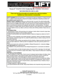
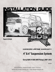
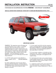
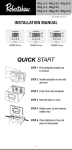
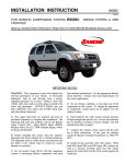
89000 Rev A
Suspension System RS66000 & RS66001
Jeep Cherokee (XJ) 1984-2001
89000 Rev A
READ ALL INSTRUCTIONS THOROUGHLY FROM START TO FINISH BEFORE BEGINNING INSTALLATION
IMPORTANT NOTES!
WARNING: This suspension system will enhance the
off-road performance of your vehicle. It will handle
differently; both on and off-road, from a factory
equipped passenger car or truck. Extreme care must
be used to prevent loss of control or vehicle rollover
during abrupt maneuvers. Failure to drive this vehicle
safely may result in serious injury or death to the driver
and passengers. ALWAYS WEAR your seat belts,
REDUCE your speed, and AVOID sharp turns and
other abrupt maneuvers.
E. Install all nuts and bolts with a flat washer. When
both SAE (small OD) and USS (large OD) washers are
used in a fastener assembly, place the USS washer
against the slotted hole and the SAE washer against
the round hole.
F. Unless otherwise specified, tighten all bolts to the
standard torque specifications listed at the end of the
note's section. USE A TORQUE WRENCH for
accurate measurements.
A. Before installing this system, have the vehicle's
alignment and frame checked at a state approved
facility.
The alignment must be within factory
specifications and the frame must be sound (no cracks,
damage, or corrosion).
G. Rancho parts come with a protective coating. Do
not powder coat, chrome, cadmium, or zinc plate any of
the components in this system. If you wish to change
the appearance of components enamel paint can be
applied over the original coating.
B. Do not install a body lift kit with Rancho’s
suspension system or interchange parts from this
system with components from another manufacturer.
Use the following Rancho shock absorbers with this
system:
Front
RS5239
RS7239
RS99239
H. Do not weld anything to these components, and
do not weld any of these components to the vehicle
unless specifically stated in the instructions. If any
component breaks or bends, contact your local Rancho
dealer or Rancho for replacement parts.
RS5000 / RS7000 / RS9000
Rear
RS5129
RS7129
RS99129
I. Some of the service procedures require the use of
special tools designed for specific procedures. The
following tools and supplies are recommended for
proper installation of this kit. C. Compare the contents of this system with the parts
list in these instructions. If any parts are missing,
including fasteners, contact the Rancho Technical
Department at 1-734-384-7804. Each hardware kit in
this system contains fasteners of high strength and
specific size. Do not substitute a fastener of lesser
strength or mix one hardware kit with another.
Jeep Service Manual
Torque Wrench (250 FT-LB capacity)
Hammer
1/2” Drive Ratchet and Sockets
Combination Wrenches
Hydraulic Floor Jack
Heavy Duty Jack stands
Wheel Chocks (Wooden Blocks)
Safety Glasses--Wear safety glasses at all times
J. It is extremely important to replace torsion bars,
CV flanges, and front drive shaft/pinion relationships as
original. Be sure to mark left/right, front/rear, and
indexing of mating parts before disassembly. A paint
marker or light colored nail polish is handy for this.
D. Apply THREAD LOCKING COMPOUND to all
bolts during installation. One drop on the exposed
threads of each bolt before installing the nut is sufficient
to provide an adequate bond. CAUTION: Thread
locking compound may irritate sensitive skin. Read
warning label on container before use.
2
K. Suspension components that use rubber or
urethane bushings should be tightened with the vehicle
at normal ride height. This will prevent premature
failure of the bushing and maintain ride comfort.
M. The required installation time for this system is
approximately 4 hours. Check off the box ( ) at the
beginning of each step when you finish it. Then when
you stop during the installation, it will be easier to find
where you need to continue from.
L. This suspension system was developed using a
31 x 11.50 x 15 tire on a 15” x 8” wheel with 3.75” of
backspacing. Before installing any other combination,
consult your local tire and wheel specialist. Actual tire
size varies by manufacturer.
N. Welding on a vehicle creates an electrical charge
throughout the body and frame. Disconnect the
vehicle’s battery prior to any welding. Place welding
ground clamps as near as possible to the weld. Never
use a vehicle suspension component as a welding
ground point.
O. Important information for the end user is contained
in the consumer/installer information pack. If you are
installing this system for someone else, place the
information pack on the driver’s seat. Please include
the installation instructions when you finish.
P. Thank you for purchasing the best suspension
system available. For the best installed system, follow
these instructions. If you do not have the tools or are
unsure of your abilities, have this system installed by a
certified technician. RANCHO IS NOT RESPONSIBLE
FOR DAMAGE OR FAILURE RESULTING FROM AN
IMPROPER INSTALLATION.
Compatible With
OE Wheels
Yes1
1
Development Tire Size (actual)
Optional Tire Size1 (actual)
Wheel Size (backspacing)
31x11.5xR15
33x12.5xR15
15x8 (3.75”)
Fitment of the optional tire size may require trimming to provide proper clearance.
Bolt Size
5/16
3/8
7/16
1/2
9/16
5/8
3/4
STANDARD BOLT TORQUE SPECIFICATIONS
INCH SYSTEM
METRIC SYSTEM
Grade 5
Grade 8
Bolt Size
Class 9.8
Class 10.9
15 FT-LB
30 FT-LB
45 FT-LB
65 FT-LB
95 FT-LB
135 FT-LB
185 FT-LB
20 FT-LB
35 FT-LB
60 FT-LB
90 FT-LB
130 FT-LB
175 FT-LB
280 FT-LB
M6
M8
M10
M12
M14
M16
M18
BOLT IDENTIFICATION
3
5 FT-LB
18 FT-LB
32 FT-LB
55 FT-LB
85 FT-LB
130 FT-LB
170 FT-LB
9 FT-LB
23 FT-LB
45 FT-LB
75 FT-LB
120 FT-LB
165FT-LB
240FT-LB
Class 12.9
12 FT-LB
27 FT-LB
50 FT-LB
90 FT-LB
145 FT-LB
210 FT-LB
290 FT-LB
12
13
14
15
8
9
9
10
3
11
5
5
6
6
4
2
1
1
7
2
PARTS LIST
No.
1
2
3
4
5
6
7
P/N
RS608
RS176637
RS860702
RS5401
94180
780281
RS89000
94119
94177
DESCRIPTION
Box 1 of 2
Front Coil Spring
Lower Link
Bushing Assy Hardware Kit
Sleeve
Lower Link Bushing
Shim .040 x 2.47 x .60
Washer .120 x 2.25 x .563
Steering Stabilizer
Information Pack
Rancho Decal
Instructions
Consumer/Warranty
Information
Warning Sticker
QTY.
No.
2
2
1
4
8
8
4
1
1
1
1
1
8
9
9
P/N
RS513
RS7455
RS7405
RS8011
10
11
RS8011
12
13
RS8302
14
RS8366
15
1
4
DESCRIPTION
Box 2 of 2
Add-A-Leaf
U Bolt (Chrysler type Rear Axle)
U Bolt (Dana 35 Rear Axle)
U-Bolt Nut/Washer Hardware Kit
½-20 Nylock Nut
½ Washer
U-Clip Hardware Kit
U-Clip
Cap
Center Bolt Nut Kit
5/16-24 Center Bolt Nut
Center Bolt Kit
5/16-24 Center Bolt
QTY.
2
4
4
1
8
8
1
4
4
1
2
1
2
FRONT SUSPENSION
6) Disconnect the drag link at the pitman arm by
removing the retaining nut.
LOWER CONTROL ARM, SHOCK ABSORBER, & COIL SPRING
REMOVAL
7) Remove the shock absorber upper nut, retainer, and
bushing. Remove the front shock absorber. DO NOT REUSE
ORIGINAL SHOCK ABSORBERS.
1) Park vehicle on a level surface. Set the parking brake
and chock rear wheels. Disconnect the negative ground cable
from the battery.
8)
2) Raise the front of the vehicle and support the frame
with jack stands, allowing the front wheels to hang. Remove
the front wheels and set them aside.
3)
Disconnect the Track Bar at the Sill Bracket.
9) Remove the passenger side lower control Arm from
the axle and frame bracket. (See Illus. 1). Retain bolts and
nuts as they will be used later for installing the new Lower
Control Arms.
Support the front axle with a floor jack.
10) Carefully lower the axle assembly using the jack.
Loosen the spring retainer and remove the coil spring.
Note: to keep the axle from tipping, work on one side of the
vehicle at a time.
CAUTION: Do not allow the front axle to hang by any hoses or
cables.
Shock Absorber
FRONT LOWER CONTROL ARM INSTALLATION
11) Push the 8 bushings (item no. 4) into the ends of the
two Lower Links (item no. 2). They generally press in by
hand, or you can use a vice.
Lower Control Arm
12) Lubricate the inside of the bushings with chassis
grease.
Illus. 1
13) Press 4 sleeves (item no. 3) into the ends of the
Links. Use a vice or a large C-clamp, if necessary.
Stabilizer Bar Link
Drag Link at
Pitman Arm
Frame End
Track Bar At
Sill Bracket
Illus. 2
Axle End
4) Disconnect the stabilizer bar links and the shock
absorber at the axle (See Illus 1 & 2).
Illus. 3
14) Determine the spacers (item 5 or 6) required for the
FRAME END of the link.
Usually these are:
Early model XJ = 2 Thin Spacers (Item 5)
Later model XJ= 2 Thick Spacers (Item 6)
5) Remove bolts and separate the brake hoses from the
frame rails. If necessary, disconnect any vent hoses and
electrical wiring from the axle.
5
(Ref Illus. 3 and 4)
Verify the spacer selection by placing the selected washers
onto the sleeve on the assembled control arm. Adjust the
number of washers, if required. You should not need to force
the combination into the pocket.
(Ref Illus. 3 and 4)
Spacers
SHOCK ABSORBER, COIL SPRING & STEERING STABILIZER
INSTALLATION
23) Install retaining washer and bushing on NEW shock
absorber, insert shock into upper mounting hole. Install
bushing, washer and nut. Tighten nut to 17 ft-lbs. Repeat for
other side.
Axle End
Illus. 4
15) Once spacer selection is determined lightly grease
the spacers.
Illus. 5
16) Slide the rear of the Rancho link into the frame with
the spacers. Correct orientation of the link is determined by
positioning the straight-out grease fitting is located under the
axle (see illus. 4), and the other one points down and to the
rear.
17) Insert the stock bolt through the frame bracket and
sleeve. If a washer was there originally, reuse it. (see Illus.
3).
18) Run the stock nut on by hand until stopped by the self
locking feature.
Spring Retainer
Illus. 6
19) Install the front of the Rancho link, with a combination
of spacers between the bushing and the axle bracket using
the criteria used in step number 13. Be sure to lightly grease
the spacers before installation.
24) Install new coil spring (item 1) and tighten the spring
retainer. (see illus. 5 & 6)
25) Raise front axle and attach shock lower mounts to
axle brackets with the original hardware. Tighten nuts and
bolts to 14 ft-lbs.
20) Insert the stock bolt through the axle bracket and
sleeve. If a washer was there originally, reuse it. (see Illus.
3).
26) While raising the axle into position, locating the top of
the spring as shown in Illus 5.
21) Run the stock nut on by hand until stopped by the self
locking feature.
27) Reconnect the track bar to the sill bracket and torque
to 62 ft-lbs. (Ref Illus 2)
22) Repeat Steps 10 thru 20 on the other side of the
vehicle.
28) Reconnect the stabilizer bar link and torque to 55 ftlbs. (Ref Illus 2).
6
29) Reconnect brake hose bolts and hoses to the frame
rails. (Ref Illus 2).
1) Park the vehicle on a level surface. Set parking
brake and chock front wheels. Raise the rear of the
vehicle and support the frame with jack stands.
30) Reconnect the drag link to the pitman using the
retaining nut. Torque to 60 ft-lbs. (Ref Illus 2).
2)
31) Remove steering stabilizer and replace with Rancho
steering stabilizer and hardware provided in the kit (item no.
7). Torque stabilizer to axle to 55 ft-lbs and stabilizer to drag
link to 35 ft-lbs.
Remove the rear wheels.
Support the rear axle with a floor jack to relieve
the tension on the leaf spring.
3)
4)
Remove the rear shock absorbers. Disconnect
the axle vent hose from the axle housing.
32) Install the wheel/tire assemblies.
Note:
Removing and installing one leaf spring
assembly at a time will prevent the rear axle from
tipping.
33) Remove the jackstands and lower the vehicle back to
the ground.
Loosen all the rear axle U-bolt nuts, but do not
remove.
34) Tighten axle and frame lower control arm nuts to 135
Ft-Lbs on both side of the vehicle.
5)
35) Grease each end of both links. As with any grease
fitting, WATCH CLOSELY, and stop greasing when grease
first appears at the ends, or if the bushings begin to move.
6) Starting with one side, remove rear axle U-bolts
and anchor plate. Remove the spring eye bolts and/or
shackles. Carefully lower the rear axle enough to
remove the leaf spring from the vehicle. Do not allow
the axle to hang from any brake lines or cables.
36) Have a front end alignment performed at a certified
alignment facility. Rancho recommends the following specs:
Caster = 7.5° ±0.5°, Toe In = 0 to 1/32”
7) Hold the spring assembly securely together with
C-clamps. See illustration 7. If applicable, remove any
leaf spring alignment clamps.
REAR SUSPENSION
8) Remove the center bolt using vise-grips to hold
the round head. If the bolt is rusted, it may be
necessary to drive the bolt out with a hammer and drift
punch.
IMPORTANT NOTES:
•
•
•
To contain the potential energy stored in a leaf
spring assembly, secure the leaves with two large
C-clamps. See illustration 7.
Some springs will have a factory helper spring
consisting of one or more flat or nearly flat leaves
installed at the bottom of the leaf pack. Do not
install your Add-A-Leaf spring in or below the helper
spring assembly.
These instructions use general procedures for
installing an Add-A-Leaf. Obtain and review your
vehicle’s service manual for specific procedures and
specifications
9)
Carefully remove the C-Clamps.
10) Apply a small amount of grease to the top ends
of the new Add-A-Leaf (item no.8), and insert it into the
leaf pack in a pyramid fashion. Keep the progressive
order of longer leaf on top.
11) Reinstall C-clamps on leaf assembly and install
a NEW center bolt and nut (item no. 14 & 15). Align
leaves and tighten center bolt to specifications (20 ft-lbs
for 5/16 center bolt).
Note: It may be necessary to cut off the center bolt if
the length is to long.
12) Remove C-clamps and reinstall the spring
assembly onto the axle with U-bolts, anchor plate,
washers and nuts. Do not tighten at this time.
13) Raise the axle and install the original eye bolts
and/or shackles. Do not tighten at this time.
14) Repeat steps 5 through 13 for installing the AddA-Leaf into the remaining leaf spring assembly.
Illus. 7
7
15) Tighten U-bolt nuts to 55 ft-lbs.
16) Install shock absorbers and torque upper and
lower nuts to 44 ft-lbs.
17) Reconnect axle vent hose
18) Install the rear wheels and lower the vehicle to
the ground. Do not release parking brake or remove
wheel chocks.
19) Jounce vehicle to settle springs. Torque eye
bolts and/or shackles to 80 ft-lbs.
20) Install the NEW leaf alignment clamps as shown
in illustration 8. Apply light pressure to the clamps when
installing them and do not bend the tabs of the clamps
sharply.
Note: The leaf alignment clamps will prevent lateral
shifting or “fanning” of the spring leaves. They are
not intended to hold the leaves against one another.
21) Check the vehicle’s alignment and adjust
headlamps.
Illus. 8
Please retain this publication for future reference. See
Important Note O.
8