1
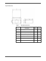
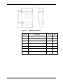
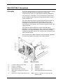
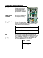
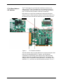
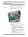
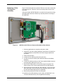
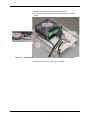
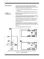
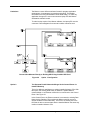
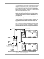
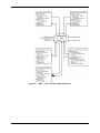
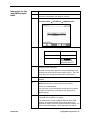
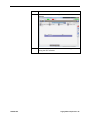
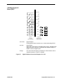
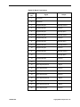
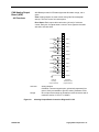
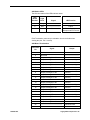
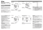
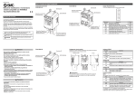
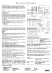
NAU SYSCON2.1 Connections
Description
This section shows differences in connections between the NAU System
Controller (SYSCON, described in Appendix 4, Legacy NAU
Components) and version 2.1 of the System Controller (SYSCON2.1).
In this document, “SYSCON2.1” refers to the System Interface Board,
version 3 (SIB3) with the Control and Communication Board, version 3
(CAC3) mounted on it.
The primary difference between original SYSCON and SYSCON2.1 is
that there are four serial ports on the SYSCON2.1 that are each
configurable for either RS-232 or RS-485. In addition, there are four
external Ethernet connections in the SYSCON2 compared to one in the
original SYSCON.
The RS-485 port differs between the original SYSCON and the
SYSCON2.1. All serial connectors are male (compared to female for the
RS-485 port in the original SYSCON). Pinout of the connector when
configured as RS-485 is shown in the Communication Connections: RS232C or RS-485 section.
The connections to the NAU SYSCON2.1 are shown below. Applicable
I/O connection diagrams are shown on the following pages.
Figure 4.
NAU Connectors
1
115 VAC or 230 VAC power supply
7
SYSCON2.1 Reset
2
Serial Port 1 (Modbus)
8
Serial Port 3
3
Serial Port 2 (e.g. Printer)
9
Serial Port 4
4
Digital outputs (system controller)
10
SYSCON2.1 Debug
5
Analog outputs and digital inputs (system
controller)
11
Ethernet Switch Board (External Ethernet)
6
System bus for add-on CAN Extension Unit
Other Slots 1, 3, 4 (counting from left) analog and
digital I/O boards
2000581-001
Installation - 17