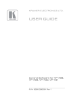
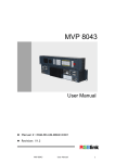
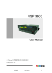
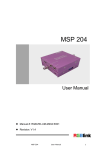
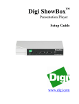
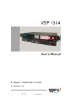
1
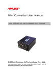
Mini Converter User Manual
MSP 218 VGA/DVI/SDI to Fiber Converter
Xiamen RGBlink Science & Technology Co., Ltd.
The pictures and data in the user manual are consult only, if
there is fluctuation, according to the real object please!
Contact Us
Headquarter: S603~604 Weiye Building Torch Hi-Tech
Industrial Development Zone Xiamen, Fujian Province, P.R.C
Shenzhen office: Room 321, Building 3, A Baiwang Plaza, Xili Nanshan District,
Shenzhen, Guangdong Province, P.R.C
Beijing office: Room 410, Building 3, Dongyi International Business Park, No.8 Gaojing
Culture Garden, Chaoyang District, Beijing, P.R.C
Shanghai office: Building 3, 1358 Nong, Tongpu Road, Shanghai, P.R.C
z
z
z
Tel: +86-592-5771197
Fax:+86-592-5771202
Websites:
~
~
z
http://www.rgblink.com
http://www.rgblink.cn
E-mail:[email protected]
File Version
Format
Time
ECO#
Description
Principal
1.0
2012/09/04
0001
Release
BIN
MSP 218 User Manual
Manual #:RGB-RD-UM-M218E001
1
CONTENT
1.0 Safety .......................................................................................................................... 3
2.0 Specification ................................................................................................................ 4
3.0 Description of button and interface.............................................................................. 5
3.1 Control panel description ..................................................................................... 5
3.2 MSP 218 RX Receiving panel interface description ............................................. 7
3.3 MSP 218 TX Sending panel interface description ............................................... 8
4.0 Communication Software Control Guide ..................................................................... 9
4.1 Running software ................................................................................................. 9
5.0 User Quick Start ........................................................................................................ 13
6.0 SFP Module manufacturer comments ....................................................................... 15
MSP 218 User Manual
Manual #:RGB-RD-UM-M218E001
2
1.0 Safety
The proper use of power
The operating voltage for this product is 220V. This product is only
workable under correct power condition, which is already mark on
the back panel of the power.
High Voltage
There are many high voltage components inside.
Do not Remove Covers and Panels
Do not remove Covers in any conditions. There are not any spare
components inside for maintenance, so do not maintain this product
by users themselves, any requirement, please feel free to contact
our service engineer. Keep heavy device from power cord.
Grounding the Product and Use the Proper Fuse
This product is grounded through the grounding conductor of the
power cord. To Avoid electrical shock, plug the power cord into a
properly wired receptacle before connecting to the product input or
output terminals.
Keep away from Magnet, Motor, TV and Transformer.
Guard Against Damp
Keep using inside clean and dryness environment, once the device
get wet, must remove power cord right now.
Keep away Exploder
Do not operate the device inside dangerous and easy explosive gas,
which it may make fire, blast or something without expectation.
Keep away Pour Liquid and Fragment
It is forbid to pour liquid, metal fragment or anything else inside this
device to avoid fire and other accident. Once that happens, must
remove power cord and try to make it clean before power on again.
MSP 218 User Manual
Manual #:RGB-RD-UM-M218E001
3
2.0 Specification
VGA Input (TX only)
Number of Input
1
Connector
Standard DB15 socket
Supported
VESA
Standards
1024x768x60;1280x1024x60;1920x1080x60;
DVI Input (TX only)
Number of Input
1
Connector
Standard DVI-I interface
Supported
VESA
Standards
1024x768x60; 1280x720x50; 1280x768x60;1280x1024x60;
1400x1050x60;1440x900x60;1920x1080x60
SDI Input (TX only, optional module)
Number of Input
1
Connector
BNC interface
Drive
Belden 1694A 150m self-adaptive 1.485G, 200m self-adaptive
2.97Gbps.
VGA Output (RX only)
Number of Output
1
Connector
Standard DB15 socket
Supported
VESA
Standards
1024x768x60;1280x1024x60;1600x1200x60;1920x1080x60
DVI Output (RX only)
Number of Output
1
Connector
Standard DVI-I interface
Supported
VESA
Standards
1024x768x60;1280x1024x60;1600x1200x60;1920x1080x60
SDI Output (TX only)
Number of Output
1
Connector
BNC interface
Drive
Belden 1694A 350m self-adaptive 270Mbps 150m self-adaptive
1.485G, 200m self-adaptive 2.97Gbps.
Optical Fiber Output (SFP module is optional)
Number of Output
1
Connector
SFP
Drive
SFP module:
SMPTE 297-2006 compatible photoelectric conversion interface,
powerful error-free transmission signal transmit 3Gbps up to 50 Mbps
30 kilometers single mode fiber, and in the worst case, the maximum
distance of 3 Gbps video pathological signal is 10 km.
Compliance
Support SDI SD-SDI,HD-SDI,3G-SDI
MSP 218 User Manual
Manual #:RGB-RD-UM-M218E001
4
Extras
Communication
RS232
Power Supply
AC 85-264 50/60Hz IEC-3 power module
Work Environment
0°C~45°C
Stored Environment
10%~90%
Product Warranty
1 year
3.0 Description of button and interface
3.1 Control panel description
1. Green light: It's on when there is DVI or VGA source input;
2. Red light: POWER lamp, it's on when the equipment is power on:
3. FORMAT LED digital, display output format value.
MSP 218 RX Receiving Panel
Digital display
Output format
1
720x576_50i
2
720x480_60i
3
1280x720_50
4
1280x720_60
5
1920x1080_50i
6
1920x1080_60i
7
1920x1080_50
8
1920x1080_60
9
1024x768_60
A
1280x1024_60
B
1600x1200_60
0
No Input
MSP 218 User Manual
Manual #:RGB-RD-UM-M218E001
5
MSP 218 TX Sending Panel
Digital display
Output format
3
1280x720_50
7
1920x1080_50
8
1920x1080_60
9
1024x768_60
A
1280x1024_60
B
1600x1200_60
0
No Input
4. Button: used for choosing the output format or source selection;
When short press the button, the relationship between sending panel and receiving panel
digital display and output signal are as follows:
MSP 218 RX Receiving Panel
Digital display
Output format
0
SFP(Fiber)
1
SDI
MSP 218 TX Sending Panel
Digital display
Output format
0
DVI
1
VGA
When long press the button, it can recall factory settings (mainly for image dislocation).
MSP 218 User Manual
Manual #:RGB-RD-UM-M218E001
6
3.2 MSP 218 RX Receiving panel interface description
1. RS232 control interface (female head) : used for console software control;
2. RS232 control interface (male head) : used for console software control;
3. DVI output: Connect the equipment which has standard DVI interface (This DVI connector
does not support hot-plugging).
4. VGA output: Connect the equipment which has standard VGA interface (This VGA
connector does not support hot-plugging).
5. SDI input: Receive SDI video signal from HD player, DVD, computer.
6. FIBER input: Connect special SFP fiber module, for video fiber input;
Note
Fiber need to insert SFP fiber module RX end, this
module is optional module;
7. Switch: Power control switch;
8. Power:AC 85-264 50/60Hz IEC-3 power interface.
Note
Support automatic switching of input signal : such as
if the current input signal is SDI input, or if SDI has no
signal input suddenly, and fiber interface has the input
signal, then the input will automatically switch to fiber
input.
MSP 218 User Manual
Manual #:RGB-RD-UM-M218E001
7
3.3 MSP 218 TX Sending panel interface description
1. RS232 control interface (female head) : used for console software control;
2. RS232 control interface (male head) : used for console software control;
3. DVI input: Receive video signal from computer, DVI signal generator, DVD player, connect
the equipment via DVI interface (This DVI connector does not support hot-plugging);
4. VGA input: Connect PC equipment;
5. SDI input: Receive video signal from HD player, HD cameras;
6. SDI output: Support equipment with SDI input, such as MSP 203;
7. FIBER output: Connect special SFP fiber module, for video fiber output;
Note
Fiber need to insert SFP fiber module RX end, this
module is optional module;
8. Switch: Power control switch;
9. Power:AC 85-264 50/60Hz IEC-3 power interface.
Note
Support automatic switching of input signal : such as
if the current input signal is VGA input, or if VGA has
no signal input suddenly, and DVI interface has the
input signal, then the input will automatically switch to
DVI input.
MSP 218 User Manual
Manual #:RGB-RD-UM-M218E001
8
4.0 Communication Software Control Guide
AVMSP series of mini converter is equipped with user-friendly communication control software.
User can use software to select between DVI, VGA, or SDI inputs, switch to Fiber, or SDI
output, and control the output resolution, DE adjustment (image shifting) and brightness
contrast, etc.
4.1 Running software
Double-click AVMSP software
z
Mini Convertor.exe, Software interface is as follows:
Serial settings
User can set Comm Port and Comm Speed (Baudrate) through "Comm setup". User can
select current using serial port by the pull-down arrow. Comm Speed should be 115200.
If select COM3, it's as follows:
Select OK, then click "Open" on the home page, connection is completed, then "Open" switch
MSP 218 User Manual
Manual #:RGB-RD-UM-M218E001
9
to "Close", it means equipment have been connected successfully, interface as below:
z
Language settings
This software supports both Chinese and English version, user can switch the language by
"language" option.
z
Advance
Advance menu are only for engineers, ordinary user do not need to set.
Save: User can save current log to specified path to review.
Remove: User can remove the log.
Factory Reset: User can set the status to the factory status.
z
About
User can find out the software version and related information in "About" menu.
MSP 218 User Manual
Manual #:RGB-RD-UM-M218E001
10
z
How to use
User need to choose current small converter Model in the pull-down firstly. Shown as below:
Click "on" button to open the serial, the button will become
when
serials opened. User can click the “OFF” button if user want to close the serial.
Click this button can realize host computer software data sync with MSP 218.
(Remark:When user change input or output format, SYNC should be started to make device
operate correctly.)
Save button, push to save Video output format, DE adjustment, brightness
contrast position and output parameters Settings.
Click this button can exit software.
MSP 218 User Manual
Manual #:RGB-RD-UM-M218E001
11
z
Sending Panel(MSP 218 TX)
The equipment will read and display the signal format of DVI,VGA or SDI interface input and
output resolution automatically, shown as above.
z
Receiving Panel(MSP 218 RX)
The equipment will read and display the signal format of SFP fiber or SDI interface input and
output resolution automatically, shown as above.
MSP 218 User Manual
Manual #:RGB-RD-UM-M218E001
12
5.0 User Quick Start
1.
Connect MSP 218 with output device.
2.
Connect one end of the power adapter with the device, the other end into a socket. Plug in,
red power indicator light means the device works normally, and green power indicator
light means the device signal input normally.
3.
How does PC software control the device?
User can use RS232 cable to realize the connection of equipment and PC to control PC;
Double click the software of AVMSP
, seen as follows:
① Select current small converter Model in the pull-down.
② User can set Comm Port and Comm Speed (Baudrate) through “Comm setup”. User can
select current using serial port by the pull-down arrow, such as COM3, Comm Speed
should be 115200.
MSP 218 User Manual
Manual #:RGB-RD-UM-M218E001
13
Click "on" button to open the serial, The button will become
.
Click this button can realize host computer software data sync with MSP 218.
(Remark:When user change input or output format, SYNC should be started to make
device operate correctly.)
③ For other operations, please refer to the fourth part Communication Software Control Guide.
Save button, push to save Video output format, DE adjustment, brightness
contrast position and output parameters Settings.
MSP 218 User Manual
Manual #:RGB-RD-UM-M218E001
14
6.0 SFP Module manufacturer comments
Manufacturer 1:
TX Panel: Model CTP 13D6-11-SDI
1310nm 3G SDI 10KM T, LC interface with DDM SFP;
RX Panel: Model CRP 13D6-11-SDI 1310nm 3G SDI 10KM R, LC interface with DDM SFP;
Manufacturer 2:
TX Panel: Model BY3L-7NLAN-SB-V0 3.3V 3.12G SM 10KM LC VSFP signal shot 1310nm;
RX Panel: Model BY3L-N7LNA-SB-V0 3.3V 3.125G SM 10KM LC VSFP single receiving;
Contact:
Wuxi electronic industrial park, No.43, Ximei Road, Wuxi national high-tech development zone,
Jiangsu Province, China
Tel: 086-510-88153666 88152666
Fax: 086-510-88152722
www.wxkeh.com
Note
SFP fiber module of manufacturers above have been
verified by our company.
MSP 218 User Manual
Manual #:RGB-RD-UM-M218E001
15