Download Technical Reference
Transcript
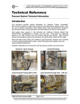
Capstone Capstone Turbine Corporation • 21211 Nordhoff Street • Chatsworth • CA 91311 • USA Telephone: (818) 734-5300 • Facsimile: (818) 734-5320 • Website: www.microturbine.com Technical Reference Model C60/C65Integrated CHP System (ICHP) Introduction This document presents technical information on operating the Capstone Integrated Combined Heat and Power (ICHP) system to create usable electrical and thermal power from a single fuel source. Refer to the Capstone MicroTurbine Product Specification (460000) and Capstone Model C60/C65 Integrated CHP System Application Guide (480007/480014) for heat recovery performance ratings, fuel input requirements, temperature/pressure efficiency data, and heat exchanger specification data. Major ICHP system components are: A Capstone Model C60 or C65 high-pressure natural gas MicroTurbine An exhaust heat recovery module (HRM) The system features user-selectable input/output functions to allow usage in a wide variety of heat recovery applications such as domestic hot water, space heating, pool heating, and industrial process hot water. The electricity provides on-site power generation for baseloading, peak shaving, and capacity addition in conjunction with local utility power. Heat Recovery Module (HRM) Model C60/C65 MicroTurbine Figure 1. Integrated Combined Heat and Power (ICHP) System 410043 Rev. G (February 2006) Page 1 of 24 This information is proprietary to Capstone Turbine Corporation. Neither this document nor the information contained herein shall be copied, disclosed to others, or used for any purposes other than the specific purpose for which this document was delivered. Capstone reserves the right to change or modify without notice, the design, the product specifications, and/or the contents of this document without incurring any obligation either with respect to equipment previously sold or in the process of construction. Capstone Turbine Corporation • 21211 Nordhoff Street • Chatsworth • CA 91311 • USA Technical Reference: Model C60/C65 Integrated CHP System (ICHP) Overview The ICHP warms incoming water by directing the MicroTurbine’s exhaust heat to the heat recovery module (HRM). Figure 2 provides an overview of the key elements in the HRM. The CHP controller drives a linear actuator, which positions an exhaust diverter in one of three positions, depending on heat recovery needs and thermal mode of operation: • Full Heat Recovery – All of the MicroTurbine exhaust is diverted to pass through the heat exchanger, thereby recovering the maximum possible thermal energy. • Full bypass (default) – MicroTurbine exhaust is directed away from the heat exchanger to recover the minimum amount of thermal energy. A small amount of heat is still captured in the heat exchanger due to conduction and radiation, so the application must allow for rejection of at least 10 Mbtu/Hr (3kW) at all times when the MicroTurbine is running. • Intermediate – In one of the thermal modes of operation, the diverter is automatically positioned to try to maintain the user-selected temperature setpoint by directing only a portion of the MicroTurbine exhaust into the HRM. The heat exchanger contains several components designed to prevent equipment damage. An internal thermostat switch shuts down the MicroTurbine if core temperatures exceed 325°F (162.8°C). A safety relief valve located on the water outlet piping protects the core from excessive pressures by opening at pressures above 850 kPa (125 psi). A water flow switch on the inlet of the heat exchanger also provides safety by shutting down the system if the minimum water flow is not detected. There is a minimum heat transfer to the hot water heat exchanger of about 10MBtu/hr (3kW) in full bypass position. Temperature can be monitored using two supplied inlet and outlet temperature sensors, or through any customer-supplied external sensor. The choice of temperature sensors to use for control is user-selectable by software settings. Refer to the section on temperature control sensor settings. Exhaust Out Water Inlet Temp (RTD) Optional Shutoff Valve (Aux Out) Press. Sensor or Remote Enable (Aux In) CHP Controller Heat Exchanger Diverter Bypass Control Core Temp Switch Water Supply Inlet Safety Relief Valve Water Supply Outlet Flow Switch (Active Closed) Intra Harness (inside MicroTurbine) Linear Actuator (with integral limit switches) Exhaust In Water Outlet Temp (RTD) Figure 2. Heat Recovery Module Operation and System Flow 410043 Rev. G (February 2006) Page 2 of 24 This information is proprietary to Capstone Turbine Corporation. Neither this document nor the information contained herein shall be copied, disclosed to others, or used for any purposes other than the specific purpose for which this document was delivered. Capstone reserves the right to change or modify without notice, the design, the product specifications, and/or the contents of this document without incurring any obligation either with respect to equipment previously sold or in the process of construction. Capstone Turbine Corporation • 21211 Nordhoff Street • Chatsworth • CA 91311 • USA Technical Reference: Model C60/C65 Integrated CHP System (ICHP) Operating Modes The ICHP provides the flexibility to operate in three thermal operating modes: Thermal Bypass (default), Electrical Priority and Thermal Priority. ICHP operating mode availability with MicroTurbine dispatch modes is discussed in the “ICHP – MicroTurbine Compatibility“ section. A cross-reference to MicroTurbine dispatch modes summarized below. ICHP Operating Mode Grid Connect Stand Alone Thermal Bypass (default) X X Electric Priority X X Thermal Priority X - Thermal Bypass – In this mode, the exhaust diverter is moved to the full bypass position, and the MicroTurbine can operate with a minimum water supply flow. A minimum water flow of 22 Gal/min (1.4 L/sec) must be maintained and the flow must be able to absorb 3kW of thermal energy transferred from exhaust. This mode may be used when thermal demand is extremely low compared with the electrical load. All normal MicroTurbine control modes are supported. Electrical Priority – In this mode, electrical power output is set to the desired level, and water temperature is set to a fixed temperature setpoint – allowing independent electrical and thermal operation. Efficiency will vary depending on both electrical and heat load requirements. Electrical Priority can be used in either Grid Connect or Stand Alone modes. In Grid Connect, electric power is controlled either as a fixed setpoint or using one of several load following schemes; water temperature is also set to a fixed setpoint. During operation, the diverter adjusts exhaust flow through the heat exchanger to maintain water temperature. This mode is typically used when either a fixed or maximum electrical output is required and sets a higher value (i.e. higher priority) on the electrical output rather than the heat output. If power demand is set too low, there may not be enough heat energy in the exhaust to reach the required temperature setpoint. Therefore, settings for power demand should also take into account the amount of thermal heat recovery required. In Stand Alone, the MicroTurbine is programmed to follow the electrical load. As in Grid Connect, the water temperature is fixed. The diverter attempts to maintain a constant water temperature, despite the varying electrical output. Thermal Priority – In this mode, the water temperature setpoint is fixed and is maintained by automatically varying the MicroTurbine electrical output. During this time, the diverter is in full recovery, routing all the exhaust heat through the heat exchanger. If the MicroTurbine is operating at its minimum speed and power (idle), the diverter will operate in bypass mode if the water temperature begins to rise above its setpoint. However, at no time will the heat exchanger be allowed to operate at an unsafe temperature. When changing modes, the diverter will be in the full bypass position for up to one minute. The capability to reach a temperature setpoint overrides the user-programmed PWRDMD request. Thermal Priority is typically used when maximum heat recovery is desired and electrical output is secondary. However, maximum efficiency can be maintained as long as minimum heat load can be achieved without opening the bypass. Thermal Priority can be used ONLY in Grid Connect mode, and cannot be used in Stand Alone operation. 410043 Rev. G (February 2006) Page 3 of 24 This information is proprietary to Capstone Turbine Corporation. Neither this document nor the information contained herein shall be copied, disclosed to others, or used for any purposes other than the specific purpose for which this document was delivered. Capstone reserves the right to change or modify without notice, the design, the product specifications, and/or the contents of this document without incurring any obligation either with respect to equipment previously sold or in the process of construction. Capstone Turbine Corporation • 21211 Nordhoff Street • Chatsworth • CA 91311 • USA Technical Reference: Model C60/C65 Integrated CHP System (ICHP) ICHP – MicroTurbine Compatibility Model C60/C65 MicroTurbine functionality integrates with ICHP operating modes to allow maximum heat and power production. However, the following limitations exist: 1. Thermal Priority mode is not allowed if MicroTurbine Load Management functions (Time of Use, Load Following) are enabled. If Thermal Priority and Time of Use are set, the MicroTurbine’s power demand will be determined by Load Management. If set to work in Thermal Bypass or Electrical Priority along with Time of Use, the userprogrammed Time of Use Power Demand value will be used. 2. The analog input selection “ELECTRICAL PWR DMD” becomes disabled when MicroTurbine Load Management functions or ICHP Thermal Priority are set. The sequence of precedence is: a. MicroTurbine Load Management b. ICHP Thermal Priority c. Analog input “ELECTRICAL POWER DEMAND” d. MicroTurbine user input for System Demand or Stored Power Demand MultiPac Operation Several ICHP systems can be connected together as a group and/or with other MicroTurbine systems to maximize power output. Power demand is shared evenly among all units in the group. However, each MicroTurbine’s heat recovery unit may operate independently to maintain its respective thermal outputs. When enabled, the CHP mode must be configured on the Master turbine or PowerServer. Subordinate turbines will use local settings until the Master sends a different mode command upon initialization of communication. The MultiPac group can be operated in any of three modes: Stand Alone, Grid Connect or Dual Mode. CHP and MultiPac operating modes work independently, which can provide application flexibility. For details on MultiPac functionality, see the MultiPac Operation Technical Reference (410032). MultiPac Temperature Settings and Control Water temperature setpoints and temperature measurement feedback can be controlled at the Master turbine, or can be assigned locally to individual turbines. These features are labeled as Setpoint (Local/Master) and Feedback (Local/Master) and are available in CRMS or through the display panel. Utilizing different setpoints for feedback can be useful when site applications require different heating. Temperature setpoints are also dependent on the CHP operating mode for functionality: In Thermal Bypass mode, the exhaust diverter fully opens to minimize heat recovery. In this mode, temperature setpoints are not referenced. In Electrical Priority mode, the CHP setpoint and feedback sources may be selected from the master or local MicroTurbine. In Thermal Priority mode, the CHP setpoint source and CHP feedback source settings are automatically set to master when thermal priority mode is selected. 410043 Rev. G (February 2006) Page 4 of 24 This information is proprietary to Capstone Turbine Corporation. Neither this document nor the information contained herein shall be copied, disclosed to others, or used for any purposes other than the specific purpose for which this document was delivered. Capstone reserves the right to change or modify without notice, the design, the product specifications, and/or the contents of this document without incurring any obligation either with respect to equipment previously sold or in the process of construction. Capstone Turbine Corporation • 21211 Nordhoff Street • Chatsworth • CA 91311 • USA Technical Reference: Model C60/C65 Integrated CHP System (ICHP) The following table summarizes available options for temperature setpoints in MultiPac mode. The setpoint and feedback sources may require each turbine to perform a different function depending on application requirements. CAUTION If the source of the water feedback is set to Master, an external temperature sensor must be used. The temperature sensor must be attached to the UCB analog input port. Failure to attach the external sensor may cause damage to the HRM (based on inaccurate temperature sensor readings). CHP Water Temperature Monitoring Options CHP Mode Source for Water Temperature Setpoint Source for Water Temperature Measurement Feedback Thermal Bypass (GC, SA) N/A N/A Electrical Priority (GC, SA) Master Master Master Local Local Master Local Local Master Master Thermal Priority (GC only) Analog inputs can be used for either the master or local MicroTurbine to provide external temperature data when separate feedback is required for several applications. Usage for Local and Master settings are described below: Local - Used when a local temperature control sensor for each application is required to regulate unique diverter position. Setpoint control is usually maintained by the master. Configure the temperature control sensor and/or temperature setpoint on each system upon commissioning. Master – Used most commonly when setpoint and/or feedback controls require only one common temperature to regulate all turbines. Configure the temperature control sensor and/or temperature setpoint on the master upon commissioning. 410043 Rev. G (February 2006) Page 5 of 24 This information is proprietary to Capstone Turbine Corporation. Neither this document nor the information contained herein shall be copied, disclosed to others, or used for any purposes other than the specific purpose for which this document was delivered. Capstone reserves the right to change or modify without notice, the design, the product specifications, and/or the contents of this document without incurring any obligation either with respect to equipment previously sold or in the process of construction. Capstone Turbine Corporation • 21211 Nordhoff Street • Chatsworth • CA 91311 • USA Technical Reference: Model C60/C65 Integrated CHP System (ICHP) Example 1 presents an instance where two separate applications using the same MultiPac output power require the same temperature setpoint but unique feedback sources. Mode: Electrical Priority Settings: CHP Setpoint source – Master CHP Feedback source – Local Scenario: Master controls water temperature setpoint for the entire MultiPac, but each MicroTurbine uses its local RTD to monitor water temperature feedback. MultiPac Electric Load Connection 3 MicroTurbines in MultiPac #1 #2 #3 75° F 75° F 75° F Thermal Application 1 Thermal Application 2 Example 2 presents an instance where three separate applications using the same MultiPac output power require unique temperature setpoints and feedback sources. Mode: Electrical Priority Settings: CHP Setpoint source – Local CHP Feedback source – Local Scenario: Each MicroTurbine uses its local RTD to control the water temperature setpoint and feedback. MultiPac Electrical Load Connection 3 MicroTurbines in MultiPac #1 #2 #3 80° F 70° F 95° F Thermal Appl. 1 Thermal Appl. 2 Thermal Appl. 3 410043 Rev. G (February 2006) Page 6 of 24 This information is proprietary to Capstone Turbine Corporation. Neither this document nor the information contained herein shall be copied, disclosed to others, or used for any purposes other than the specific purpose for which this document was delivered. Capstone reserves the right to change or modify without notice, the design, the product specifications, and/or the contents of this document without incurring any obligation either with respect to equipment previously sold or in the process of construction. Capstone Turbine Corporation • 21211 Nordhoff Street • Chatsworth • CA 91311 • USA Technical Reference: Model C60/C65 Integrated CHP System (ICHP) Dual Mode Considerations In dual mode, any of the three CHP modes are allowed. No configuration changes will take place if the CHP is set to run in Thermal Bypass or Electrical Priority modes and the system automatically switches from Grid Connect to Stand Alone (or visa-versa). However, if the CHP is configured to work in Thermal Priority and the loss of grid is detected, the following sequence of events will occur: 1. The entire MultiPac will shut down and restart in Stand Alone mode. 2. CHP mode will switch to Electrical Priority to continue heat recovery. 3. No changes will be made to the setpoint and temperature feedback settings. While in Stand Alone, upon detecting the grid: 1. The entire MultiPac will shut down and restart in Grid Connect mode. 2. CHP mode will switch to Thermal Priority. 3. No changes will be made to the setpoint and temperature feedback settings. 410043 Rev. G (February 2006) Page 7 of 24 This information is proprietary to Capstone Turbine Corporation. Neither this document nor the information contained herein shall be copied, disclosed to others, or used for any purposes other than the specific purpose for which this document was delivered. Capstone reserves the right to change or modify without notice, the design, the product specifications, and/or the contents of this document without incurring any obligation either with respect to equipment previously sold or in the process of construction. Capstone Turbine Corporation • 21211 Nordhoff Street • Chatsworth • CA 91311 • USA Technical Reference: Model C60/C65 Integrated CHP System (ICHP) Hardware Connections MicroTurbine hardware connections are described in the paragraphs below. MicroTurbine UCB Connections NOTE See the Model C60/C65 Electrical Technical Reference (410001) for a complete set of UCB pin definitions and electrical ratings. J4 J7 J5 J3 User Maintenance J2 J1 Ethernet J16 J12 J10 1 J15 J11 J14 Analog Inputs (Pins 3-5 = Analog Inputs 1, 2 and 3) J15 Output Relays (Pins 1-12 = Output Relays 1 to 6. Relays are user-selectable) 1 J14 1 1 1 1 J13 Intra-A MultiPack Intra-B J6 J8 Figure 3. Model C60/C65 UCB Connections J14 Analog Inputs An external temperature sensor may be connected to one of three UCB analog inputs. • Electrically connect one end to pin 3 (ANIN1), 4 (ANIN2) or 5 (ANIN3). • Connect the other side to pin 2 or 6 (AGND). Refer to the UCB Analog Inputs section under “Software Settings”. J15 Output Relays An external device, such as a water pump, may be attached to one of six UCB output solidstate relay contacts, to remotely control pump operation. Use of an interposing relay may be required for large current draws. • UCB Output relays are arranged in six pairs of pins. Electrically connect the device to connector J15,(pins 1,2 …11,12). These correspond to relays AC1-A,B…AC6- A,B. Refer to the UCB Output Relays Menu section under “Software Settings”. 410043 Rev. G (February 2006) Page 8 of 24 This information is proprietary to Capstone Turbine Corporation. Neither this document nor the information contained herein shall be copied, disclosed to others, or used for any purposes other than the specific purpose for which this document was delivered. Capstone reserves the right to change or modify without notice, the design, the product specifications, and/or the contents of this document without incurring any obligation either with respect to equipment previously sold or in the process of construction. Capstone Turbine Corporation • 21211 Nordhoff Street • Chatsworth • CA 91311 • USA Technical Reference: Model C60/C65 Integrated CHP System (ICHP) Heat Recovery Module (HRM) Components Major elements in the heat recovery portion of the ICHP system are described below. For detailed information on MicroTurbine functionality, see the Capstone Users Manual (400001). Bleed Valve (behind panel) Thermostat Safety Relief (515011) (515081) Valve (515085) Flow Switch (515491) Water Outlet Linear Actuator (515919) Control Board (514675) Drain Pipe Heat Exchanger Water Inlet RTD Sensors (515009) Figure 4. ICHP Heat Recovery Module HRM Control Board Settings Connector J4, Pins 1 and 2 are jumpered if no auxiliary (external) equipment will be used. J4 Pin Assignments 1- AUX IN 2 - ISO PGND 3 – AUX OUT 4 - PGND 5 - CHASSIS (Optional) External devices may be connected as follows: Auxilliary Outputs: - Shutoff Valve (J4, pins 3, 4) Auxilliary Inputs: - Pressure Sensor - Remote Enable (J4, pins 1,2) Connector J4 Figure 5. HRM Control Board 410043 Rev. G (February 2006) Page 9 of 24 This information is proprietary to Capstone Turbine Corporation. Neither this document nor the information contained herein shall be copied, disclosed to others, or used for any purposes other than the specific purpose for which this document was delivered. Capstone reserves the right to change or modify without notice, the design, the product specifications, and/or the contents of this document without incurring any obligation either with respect to equipment previously sold or in the process of construction. Capstone Turbine Corporation • 21211 Nordhoff Street • Chatsworth • CA 91311 • USA Technical Reference: Model C60/C65 Integrated CHP System (ICHP) Software Settings Software settings can be configured using the MicroTurbine display panel or CRMS. Display Panel NOTE A full chart showing available CHP menu selections from the MicroTurbine display panel is presented in the Capstone User’s Manual (400001). CHP Config Menu The top-level CHP Config menu sets parameters affecting the CHP functionality. Limits are usually established when the MicroTurbine is commissioned and are not changed once set. CHP Installed <Yes/No> Setting designates whether the particular unit functions with the CHP integrated package installed and must be set to <Yes>. If this setting is set to <No>, a Start Configuration Fault (17000) will occur when the MicroTurbine <Start> command is issued. Mode <Option> Sets the CHP operating mode and (once selected) operation is automatic. If a MultiPac group has been configured and communication established, the temperature setpoint and the selected operating mode below will be passed to subordinate turbines in the group. • Thermal Bypass • Electrical Priority • Thermal Priority Data Source <Setpoint/Feedback> Sets control of water temperature sensor readings at the setpoint and feedback loops for the master and/or local (subordinate) turbines. See the MultiPac Operation, “Temperature Settings and Controls” section for examples and further explanation. Temperature Setpoint <°F> Sets the CHP water temperature setpoint (32 – 221 °F). Due to differences in loads, actual temperature may have variance (Electrical Priority: ±7 ° F, Thermal Priority: ±5 °F). OverTemperature Bypass <°F > Sets the water temperature setpoint at which an Overtemp Fault is declared in Thermal Bypass mode. This value is ignored in Thermal or Electrical Priority modes. As shipped, the factory default is 120 °F. Adjustable range is from 120 to 224 °F. OverTemperature Recovery <°F > Sets the water temperature setpoint at which an Overtemp Fault is declared in Thermal Priority and Electrical Priority mode. This value is ignored in Thermal Bypass mode. As shipped, the factory default is 120 °F. Adjustable range is from 120 to 224 °F. 410043 Rev. G (February 2006) Page 10 of 24 This information is proprietary to Capstone Turbine Corporation. Neither this document nor the information contained herein shall be copied, disclosed to others, or used for any purposes other than the specific purpose for which this document was delivered. Capstone reserves the right to change or modify without notice, the design, the product specifications, and/or the contents of this document without incurring any obligation either with respect to equipment previously sold or in the process of construction. Capstone Turbine Corporation • 21211 Nordhoff Street • Chatsworth • CA 91311 • USA Technical Reference: Model C60/C65 Integrated CHP System (ICHP) CHP Control Resistive Temperature Device (RTD) <Inlet/Outlet> User setting that selects the inlet or outlet RTD as the controlling sensor to provide temperature measurement feedback to the HRM. This setting is overridden if temperature data is received from an external temperature sensor (see UCB Analog Inputs section for configuration). UCB Analog Inputs The top-level UCB Analog Inputs menu sets functionality for up to three analog inputs that may be selectively mapped on the User Connection Board. An analog input assignment to a PWRDMD is reset to “Not Assigned” when Load Management functions are enabled. Functionality is usually established at installation and not changed. Input Number <Number> Selects one of three available analog inputs. Function <Number> Assigns one of three available functions if an external sensor is installed: • Unused • Power Dmd – Displays the output power demand • CHP Flow – Displays the water flow measurement in Gal/min • CHP Ext Fdbk – Displays temperature from the external sensor. selected as a temperature control sensor. May be Mode <Current/Voltage> Selects the current (4 - 20mA) or voltage (0 - 5Vdc) parameter range. For 0 – 5 Vdc, the full input range is scaled. When 4 - 20 mA is used, the range is scaled between .9V (min.) and 4.5V (max.) and a customer-supplied 250 ohm resistor must be installed. Voltages outside the stated range are faults. Lower Limit <mA/V> Selects the lower scale value of the optional sensor. Example: CHP Flow: 0 Gal/min = 0 Volts (4 mA) CHP Ext Fdbk: 32° F = 0 Volts (4 mA) Power Demand: 0 kW = 0 Volts (4 mA) Upper Limit <mA/V> Selects the upper scale value of the optional sensor. Example: CHP Flow: 80 Gal/min = 5 Volts (20 mA) CHP Ext Fdbk: 212° F = 5 Volts (20 mA) Power Demand: 2.09 MW = 5 Volts (20 mA) 410043 Rev. G (February 2006) Page 11 of 24 This information is proprietary to Capstone Turbine Corporation. Neither this document nor the information contained herein shall be copied, disclosed to others, or used for any purposes other than the specific purpose for which this document was delivered. Capstone reserves the right to change or modify without notice, the design, the product specifications, and/or the contents of this document without incurring any obligation either with respect to equipment previously sold or in the process of construction. Capstone Turbine Corporation • 21211 Nordhoff Street • Chatsworth • CA 91311 • USA Technical Reference: Model C60/C65 Integrated CHP System (ICHP) UCB Output Relays Menu The UCB Output Relays menu sets functionality for the available output relays on the UCB. This functionality is usually established at installation and not changed. Relay Number <Number 1-6> Selects one of six available output relay numbers. Option <Function> Sets the output relay function. There is one function relating to ICHP (listed below): • CHP Active – The signal is active when the system detects MicroTurbine exhaust gas flow. The CHP Active signal can be used to activate an external device, such as a water pump. The signal can be set active high or active low by using the State option. State <Active Open/ Active Closed> Sets the relay state as “Active Open” or “Active Closed”: Unit Data The top-level Unit Data menu displays real-time data for individual MicroTurbines. If accessed from the master turbine in a MultiPac group, parameter data for all grouped turbines can be displayed. Only CHP-related options are described here – see the MicroTurbine User’s Manual (400001) for the complete set of Unit Data menu options. Turbine <Number> Selects one of 20 turbines (1-20). Option <Parameter> • ICHP Water In Temperature Displays temperature feedback based on the inlet RTD. • ICHP Water Out Temperature Displays temperature feedback based on the outlet RTD. • ICHP Temp Feedback Displays temperature data from the inlet, outlet or external sensor – whichever has been selected as the temperature control sensor. If an inlet sensor is used, this value will be the same as the “ICHP Water In Temperature” value. If an outlet sensor is used, this value will be the same as the “ICHP Water Out Temperature” value. If an external sensor is used for feedback, the value used will be obtained from the analog input. • Diverter State Displays the relative diverter position (bypass, recovery, middle). 410043 Rev. G (February 2006) Page 12 of 24 This information is proprietary to Capstone Turbine Corporation. Neither this document nor the information contained herein shall be copied, disclosed to others, or used for any purposes other than the specific purpose for which this document was delivered. Capstone reserves the right to change or modify without notice, the design, the product specifications, and/or the contents of this document without incurring any obligation either with respect to equipment previously sold or in the process of construction. Capstone Turbine Corporation • 21211 Nordhoff Street • Chatsworth • CA 91311 • USA Technical Reference: Model C60/C65 Integrated CHP System (ICHP) CRMS Software settings described in the Display Panel section may be adjusted in CRMS (V4.32 or greater) as well. See Figures 6 through 8 for illustrative purposes. NOTE CRMS menu selections are described in the CRMS User’s Level (410013) and Maintenance Level (410014) Technical Reference manuals. To view the CHP Display Panel, select [Settings][CHP Control] from the CRMS MicroTurbine Menu Bar. CHP Settings CHP Control RTD <Inlet, Outlet, External> (Ext. sensor grays display) CHP Mode Selection Flow Rate (Display only) CHP Installed Toggle <Yes/No> Temperature Feedback for selected sensor (Display only) Temperature Setpoint (Sets water temp) (External Device) Diverter Position (Indicates relative position of diverter) Water Flow status Water Inlet and Outlet Temperature (Display only) CHP Control Board Temperature (Display only) MultiPac Settings (Available only on Master) Linear Actuator Motor Current (Display only) Overtemperature Limits Settings Figure 6. CRMS CHP Display Panel Figure 7. MultiPac Settings 410043 Rev. G (February 2006) Figure 8. Overtemperature Limits Page 13 of 24 This information is proprietary to Capstone Turbine Corporation. Neither this document nor the information contained herein shall be copied, disclosed to others, or used for any purposes other than the specific purpose for which this document was delivered. Capstone reserves the right to change or modify without notice, the design, the product specifications, and/or the contents of this document without incurring any obligation either with respect to equipment previously sold or in the process of construction. Capstone Turbine Corporation • 21211 Nordhoff Street • Chatsworth • CA 91311 • USA Technical Reference: Model C60/C65 Integrated CHP System (ICHP) Graphical representations which are displayed on the CRMS version and not presently implemented on the Display Panel are described below. See the section on the “Display Panel” for all other descriptions. CHP Settings Flow Rate <Gal/min> Displays the water flow rate setpoint. This data is not presented on the display panel. Water Flow Status Circular ring that changes color to represent the real time water flow/no-flow condition in the HRM. Diverter Position (no units) Graphically represents the relative position and direction of movement of the exhaust diverter. The diverter lever can be in one of three positions: full bypass, full recovery, and mid-bypass/recovery. CHP Control Board Temperature <°F > Displays the temperature of the CHP control board in degrees F. Linear Actuator Motor Current (mA) Displays the current draw from the Linear Actuator circuitry. UCB Analog Settings To display or change values for the three available analog inputs, click on the [Settings][User Connection Bay Settings] option from the CRMS MicroTurbine menu bar, then select the desired relay UCB Analog function from the dropdown menu. The hardware settings are described in the UCB Analog Inputs section. 410043 Rev. G (February 2006) Page 14 of 24 This information is proprietary to Capstone Turbine Corporation. Neither this document nor the information contained herein shall be copied, disclosed to others, or used for any purposes other than the specific purpose for which this document was delivered. Capstone reserves the right to change or modify without notice, the design, the product specifications, and/or the contents of this document without incurring any obligation either with respect to equipment previously sold or in the process of construction. Capstone Turbine Corporation • 21211 Nordhoff Street • Chatsworth • CA 91311 • USA Technical Reference: Model C60/C65 Integrated CHP System (ICHP) UCB Output Relays Menu To display or change values for the six available output relays, click on the [Settings][User Connection Bay Settings] option from the CRMS MicroTurbine menu bar, then select the desired relay UCB Output Relay function from the dropdown menu. Refer to the Model C60/C65 Electrical Technical Reference (410001) manual for further details on output relay functionality. Output Relays (Relays 1-6) Output Relay Functions Lower/Upper Limits (Set scale values) Analog Inputs (Inputs 1-3) Analog Input Mode (Voltage/Current) Analog Input Functions Figure 9. CRMS UCB Analog Inputs/Output Relays Settings Panel 410043 Rev. G (February 2006) Page 15 of 24 This information is proprietary to Capstone Turbine Corporation. Neither this document nor the information contained herein shall be copied, disclosed to others, or used for any purposes other than the specific purpose for which this document was delivered. Capstone reserves the right to change or modify without notice, the design, the product specifications, and/or the contents of this document without incurring any obligation either with respect to equipment previously sold or in the process of construction. Capstone Turbine Corporation • 21211 Nordhoff Street • Chatsworth • CA 91311 • USA Technical Reference: Integrated Combined Heat and Power (ICHP) Installation and Commissioning the System NOTE Answers to common application issues may be found in the “C60 or C65 Integrated CHP Application Guide” (480007 or 480014). Installation Overview Listed below is sequential list of installation steps in the order of operation. • Relocate the MicroTurbine (with HRM attached) into the building location. De-stack and re-stack, if required. Refer to sections - “HRM Removal from the MicroTurbine (Destacking)” and “HRM Re-attachment to the MicroTurbine (Stacking)”. • Bolt the unit down in a location that meets all service area access and connection needs, if required. • Install water, fuel and electrical connections. • Run water loop and purge all air from the HRM. Refer to the fill procedure in the “Plumbing Connections and HRM Fill” section. • Provide power to the system. • Program all required settings, limits, modes and controls. 9 Set CHP Installed function to YES. 9 Select the CHP operating mode (Thermal Priority, Electrical Priority or Thermal Bypass). 9 Select a temperature sensor device (inlet, outlet or external). If an external sensor is selected, the sensor must first be installed. 9 Set water temperature setpoint value. 9 Configure analog input (if required). 9 Set the temperature feedback source. Configure the source as Local or Master (if MultiPac enabled). 9 Establish and set over-temperature limit points. • Provide fuel to the system. • Ensure that water will be flowing upon MicroTurbine startup. • Start the MicroTurbine. • Verify water heating, bypass and recovery functions and power output are consistent with user software settings. 410043 Rev. G (February 2006) Page 16 of 24 This information is proprietary to Capstone Turbine Corporation. Neither this document nor the information contained herein shall be copied, disclosed to others, or used for any purposes other than the specific purpose for which this document was delivered. Capstone reserves the right to change or modify without notice, the design, the product specifications, and/or the contents of this document without incurring any obligation either with respect to equipment previously sold or in the process of construction. Capstone Turbine Corporation • 21211 Nordhoff Street • Chatsworth • CA 91311 • USA Technical Reference: Model C60/C65 Integrated CHP System (ICHP) HRM Removal from the MicroTurbine (De-stacking) It may be necessary, due to space limitations, to remove (de-stack) the HRM to get the system through doorways or other low-clearance passageways. NOTE This procedure assumes that the HRM water inlet, water outlet and drain have not yet been connected. WARNING All MicroTurbine and ICHP power MUST BE shutoff and detached during this process to prevent accidental electrical shock. In addition, the fuel source MUST BE detached from the MicroTurbine. Follow these steps to remove the HRM from the MicroTurbine: 1. Remove the HRM side panels, front panel, rear panels and rear rain hood using a 10mm socket. 2. Remove the C60/C65 upper side panels using a 10-mm socket. 3. Remove the ICHP Control Board with bracket: a. Disconnect the Intra Harness cable 510074 (W102) from the ICHP Control Board at connector J2. b. Disconnect the sensor cable assembly 516109 (W126) from the ICHP Control Board at connector J3. Then, feed the harness up into the HRM cavity to prevent damage during removal. c. Disconnect any connected analog Inputs from the ICHP Control Board at connector J4. d. Detach the control board bracket (with attached board) by removing one (1) 10 mm hex-head bolt, and sliding the bracket slightly to the rear for clearance. 4. Loosen the exhaust duct interface band clamp with a 7/16-inch deep socket. Slide the flexible exhaust interface downward, away from the HRM ducting. 5. Remove the four bolts (unstacked MicroTurbine eyebolt location) that hold the HRM and MicroTurbine C60/C65 chassis. Use a 3/4-inch socket and combination wrench to remove the bolts. See Figure 10 for HRM mounting bolt location. Mounting Bolt (1 of 4 shown) Front View Figure 10. HRM Mounting Bolt Location 410043 Rev. G (February 2006) Page 17 of 24 This information is proprietary to Capstone Turbine Corporation. Neither this document nor the information contained herein shall be copied, disclosed to others, or used for any purposes other than the specific purpose for which this document was delivered. Capstone reserves the right to change or modify without notice, the design, the product specifications, and/or the contents of this document without incurring any obligation either with respect to equipment previously sold or in the process of construction. Capstone Turbine Corporation • 21211 Nordhoff Street • Chatsworth • CA 91311 • USA Technical Reference: Model C60/C65 Integrated CHP System (ICHP) 6. Slide the HRM towards the back of the MicroTurbine chassis, approximately 0.5 to 1 inch. The HRM may have to be slightly lifted to overcome the rivet heads on the MicroTurbine chassis. CAUTION The HRM weighs approximately 450 lbs and may cause injury if best practices for lifting heavy equipment are not followed. 7. Lift the HRM off of the MicroTurbine chassis using a forklift on the four eye-bolts. Ensure that the lifting sling is at an angle no greater than 30° from vertical to prevent buckling of the HRM frame. Use a spreader bar if necessary. 8. Safely lower the HRM over a set of 4 x 4 wood blocks, so that the inlet duct (which extends 2-inches below the HRM side rails) does not support the weight of the HRM. HRM Re-attachment to the MicroTurbine (Stacking) Follow these steps to re-attach the HRM to the MicroTurbine: 1. Lift and position the HRM (using the eye bolts) on top the MicroTurbine slightly to the rear of center. Ensure that the lifting sling or cable is at an angle no greater than 30 degrees from vertical to prevent bucking of the HRM frame. Use a spreader bar, if necessary. 2. Slide the HRM towards the front of the MicroTurbine chassis until the flexible seal on the underside of the HRM meets the MicroTurbine firewall. The HRM may have to be slightly lifted to overcome the rivet heads on the MicroTurbine chassis. 3. Install the four (4) bolts that mount the HRM to the MicroTurbine chassis. 4. Install aluminum tape to cover the seam between the HRM and MicroTurbine chassis. The tape prevents exhaust leakage from the HRM from entering the engine inlet cavity. 5. Slide the flexible exhaust interface up onto the HRM ducting. 6. Slide up the interface band clamp and tighten with a 7/16-inch deep socket. 7. Re-attach the control board bracket (with PCBA attached) to the underside of the HRM. 8. Feed the sensor cable assembly 516109 (W126) from the HRM cavity into the engine air inlet cavity and reattach to connector J3. 9. Reattach intra harness cable 510074 (W102) to the control board at connector J2. 10. Verify that the HRM control board has configuration jumpers on J4, pins 1 and 2 (see Figure 5), or an Aux Input is installed. 11. Install the MicroTurbine top side panels. 12. Install the HRM side panels, front panel and rear panels. 410043 Rev. G (February 2006) Page 18 of 24 This information is proprietary to Capstone Turbine Corporation. Neither this document nor the information contained herein shall be copied, disclosed to others, or used for any purposes other than the specific purpose for which this document was delivered. Capstone reserves the right to change or modify without notice, the design, the product specifications, and/or the contents of this document without incurring any obligation either with respect to equipment previously sold or in the process of construction. Capstone Turbine Corporation • 21211 Nordhoff Street • Chatsworth • CA 91311 • USA Technical Reference: Model C60/C65 Integrated CHP System (ICHP) Plumbing Connections and HRM Fill Perform the following steps to commission the ICHP system: WARNING All MicroTurbine and ICHP power MUST BE shutoff during this process to prevent accidental electrical shock. Plumbing Connections 1. Create the necessary access area for plumbing installation by removing the rain hood (not shown) and upper service access panel from the rear of the HRM unit. a. Detach the rain hood by removing four (4) M6 hex-head bolts. b. Detach the upper service access panel by detaching five (5) #10 hex-head bolts. Bleed Valve (behind panel – not shown) Upper HRM Service Access Attach Bolts (1 of 5 shown) Water Outlet Water Inlet Drain Pipe Safety Relief Valve Drain Figure 11. HRM (Rear View) 2. Attach customer drain plumbing to the rear of the HRM unit. Use Teflon pipe tape to minimize leakage. A recommended pipe clearance of at least 36 inches is suggested to allow for the UCB connection box service clearance. 3. Pipe fitting sizes for HRM plumbing components are presented below: Description Fitting Size Inlet and Outlet Fitting, Brass, 2-inch NPT, Female Safety Relief Valve Fitting, Female, 1-inch NPT Water Drain Pipe Fitting, Female, 1/2 -inch NPT Bleed Valve (behind panel) Fitting, Female, 1/8-inch NPT 410043 Rev. G (February 2006) Page 19 of 24 This information is proprietary to Capstone Turbine Corporation. Neither this document nor the information contained herein shall be copied, disclosed to others, or used for any purposes other than the specific purpose for which this document was delivered. Capstone reserves the right to change or modify without notice, the design, the product specifications, and/or the contents of this document without incurring any obligation either with respect to equipment previously sold or in the process of construction. Capstone Turbine Corporation • 21211 Nordhoff Street • Chatsworth • CA 91311 • USA Technical Reference: Model C60/C65 Integrated CHP System (ICHP) External (Optional) Connections Install external pressure gauges, vent valves and flow meters (as needed) to the existing plumbing to ensure nominal water flow, adequate pressure and removal of trapped air in the system. The factory installed HRM does not include isolation or drain valves, so these must be externally installed to match the needs of the installation. NOTE It may be useful to use a transparent drain piping to be able to inspect the drain for leakage. The piping must be temperature rated for 250° F. Other equipment that may provide useful telemetry: pressure gauges, flow meters, air separators (in systems that have entrained air), and expansion tanks. Keep in mind that lower temperature components can be used on the inlet side as long as they are appropriate for the installation. WARNING Drains for the outlet loop, safety relief and drain should not be tied together because high pressure venting through the safety relief valve could blow back into the drain. A typical installation is as follows: OPEN TO AIR ISOLATION VALVE VENT VALVE Vent must be at highest point. VENT VALVE WATER INLET ISOLATION VALVE WATER OUTLET DRAIN VALVE HRM Drain must be at lowest point. SAFETY RELIEF PLUMB TO DRAIN DRAIN PIPE PLUMB TO DRAIN EXTERNAL TO HRM NOTE: Some condensation is normal. Large amounts of water may indicate a leak. INCLUDED IN HRM Figure 12. Typical ICHP Plumbing Installation 410043 Rev. G (February 2006) Page 20 of 24 This information is proprietary to Capstone Turbine Corporation. Neither this document nor the information contained herein shall be copied, disclosed to others, or used for any purposes other than the specific purpose for which this document was delivered. Capstone reserves the right to change or modify without notice, the design, the product specifications, and/or the contents of this document without incurring any obligation either with respect to equipment previously sold or in the process of construction. Capstone Turbine Corporation • 21211 Nordhoff Street • Chatsworth • CA 91311 • USA Technical Reference: Model C60/C65 Integrated CHP System (ICHP) Fill Procedure 1. Perform the following steps to fill the heat exchanger with water: NOTE Since each customer likely will have a unique water loop, this fill procedure is described in general terms. Estimated completion time is 60 minutes. Bleed Valve Water Flow Switch (For info only) Drain Pipe Fitting Thermostat (for info only) Safety Relief Valve (For info only) Outlet RTD Temp Sensor (For info only) Water Outlet Figure 13. Heat Recovery Module (Rear View) a. Remove all pre-existing water in the heat exchanger. b. Install bleed valves at all customer high points to remove trapped air. The heat exchanger is provided with a factory-installed bleed valve at its high point. c. Flex hose or tubing should be attached to all drain and vent valves so the water produced during the bleed process may be drained to a safe location. d. Assure all bleed valves are open (only one is factory-installed in HRM). e. Open all isolation valves (if installed). f. Operate the customer pump to flow water. Makeup (city) water should be turned on to force air forward out of the system, both through the bleed valves, and through the 2-inch outlet port. g. Close other customer valves to ensure makeup (city) water is being used to force air from the heat recovery unit. h. If the customer has a valve on the outlet port, it should be partially closed so air is also forced out of the smaller bleed valve. i. Wait for bleed lines to yield water only (no air), and then close the bleed valves. j. After air stops from all bleed lines, open the inlet and outlet isolation valves. 410043 Rev. G (February 2006) Page 21 of 24 This information is proprietary to Capstone Turbine Corporation. Neither this document nor the information contained herein shall be copied, disclosed to others, or used for any purposes other than the specific purpose for which this document was delivered. Capstone reserves the right to change or modify without notice, the design, the product specifications, and/or the contents of this document without incurring any obligation either with respect to equipment previously sold or in the process of construction. Capstone Turbine Corporation • 21211 Nordhoff Street • Chatsworth • CA 91311 • USA Technical Reference: Model C60/C65 Integrated CHP System (ICHP) k. If the customer pump has a variable speed drive (VSD), the pump should be operated at the lowest speed possible. This prevents any remaining air from being “beaten” into the water - which can create foam that is difficult to remove. l. Run the makeup water and pump for 15-20 minutes. m. Stop the pump, but continue to allow makeup water to flow, and let the system settle for five minutes. n. Open the bleed valve. Trapped air will rise to surface and exit via bleed valves. o. Restart the pump, and allow water to circulate for ten more minutes. p. Check all bleed valves for air. If air is found, stop the pump, bleed the air, and then allow the system to settle for five more minutes. Restart the pump and repeat check of bleed valves. q. When all bleed valves yield water, the system is primed. r. Close all bleed valves. Verify that no leaks are present from any connected pipe fitting. If a leak is present, shut down the system and re-secure pipe attachments. s. For a closed loop system, turn off the makeup water. 2. Set the VSD on customer pump to the desired speed. Control Board Configuration Verify that the HRM control board has configuration jumpers on J4, pins 1 and 2 (see Figure 5), or an Auxiliary Input is installed. NOTE Failure to install a jumper on pins 1 and 2 (AUX IN and ISO PGND),or disconnecting the intra-harness will cause a “17001 CHP Config Error”. 1. Open the MicroTurbine front door to access the control board. 2. Remove the control board cover by detaching two (2) 7/16-inch bolts. 3. Install a jumper between pins 1 and 2, or configure AUX IN (pin 1) as required. Final Preparation 1. Replace all HRM and MicroTurbine access panels. 2. Configure software settings as follows (Display Panel or CRMS): a. Set CHP Installed function to YES. b. Select the CHP operating mode (Thermal Priority, Electrical Priority or Thermal Bypass). c. Select a temperature sensor device (inlet, outlet or external). If an external sensor is selected, the sensor must first be installed. d. Set water temperature setpoint value. e. Configure analog inputs (if required). 410043 Rev. G (February 2006) Page 22 of 24 This information is proprietary to Capstone Turbine Corporation. Neither this document nor the information contained herein shall be copied, disclosed to others, or used for any purposes other than the specific purpose for which this document was delivered. Capstone reserves the right to change or modify without notice, the design, the product specifications, and/or the contents of this document without incurring any obligation either with respect to equipment previously sold or in the process of construction. Capstone Turbine Corporation • 21211 Nordhoff Street • Chatsworth • CA 91311 • USA Technical Reference: Model C60/C65 Integrated CHP System (ICHP) f. Set the temperature feedback source. Configure turbine as Local or Master, if MultiPac enabled. g. Establish over-temperature limit points. See description of the “OverTemperature Bypass” and “OverTemperature Recovery” settings in the Display Panel, “CHP Config Menu” section. 3. Apply power to the MicroTurbine. 4. Apply fuel to the MicroTurbine fuel inlet. 5. Ensure water flow upon MicroTurbine startup. 6. Start the MicroTurbine. Servicing the ICHP System Troubleshooting the System If problems arise in the ICHP system, refer to the 17000 faults section in the Capstone Model C60 Troubleshooting Guide (430013). If information from the Troubleshooting Guide does not resolve the problem, call Capstone Technical Support. Draining the System Perform the following steps to drain the HRM: 1. Turn off the makeup (city) water. 2. Isolate the heat exchanger inlet by closing all external (isolation) valve(s). 3. Open the heat exchanger bleed port (or other external vent valve) to allow air to enter, and displace the water being drained from the system. 4. Open the lowest port (external to the HRM) to drain water. 5. Allow water to drain from system. 410043 Rev. G (February 2006) Page 23 of 24 This information is proprietary to Capstone Turbine Corporation. Neither this document nor the information contained herein shall be copied, disclosed to others, or used for any purposes other than the specific purpose for which this document was delivered. Capstone reserves the right to change or modify without notice, the design, the product specifications, and/or the contents of this document without incurring any obligation either with respect to equipment previously sold or in the process of construction. Capstone Turbine Corporation • 21211 Nordhoff Street • Chatsworth • CA 91311 • USA Technical Reference: Model C60/C65 Integrated CHP System (ICHP) Related Documentation The following table lists applicable ICHP technical documentation. Document No. Document Title 400000 Capstone MicroTurbine User’s Manual 410001 Capstone Model C60/C65 Electrical Technical Reference 410005 Capstone Model C60 Performance Technical Reference 410013 Capstone Remote Monitoring System (Users Edition) Technical Reference 410032 MultiPac Operation Technical Reference 410048 Capstone Model C65 Performance Technical Reference 430013 Capstone Model C60 Troubleshooting Guide (see 17000 faults) 430017 Capstone Model C60 Service Manual 440057 ICHP Control Board Replacement Work Instructions 440058 ICHP Linear Actuator Replacement Work Instructions 440059 ICHP Bleed Valve Replacement Work Instructions 440060 ICHP Flow Switch Replacement Work Instructions 440061 ICHP Resistive Temperature Device (RTD) Replacement Work Instructions 440062 ICHP Thermostat Replacement Work Instructions 440063 ICHP Safety Relief Valve Replacement Work Instructions 440064 ICHP Sensor Cable Replacement Work Instructions 440052 Commissioning Checklist Procedures Work Instructions 460006 Capstone Commissioning Checklist 480007 Capstone Model C60 Integrated CHP System Application Guide 480014 Capstone Model C65 Integrated CHP System Application Guide Capstone Technical Information If questions arise regarding ICHP operation after reviewing Capstone documentation, please contact the Technical Support department for assistance and information. Capstone Technical Support Toll Free Telephone: (877) 282-8966 Service Telephone: (818) 407-3600 • Fax: (818) 734-1080 E-mail: [email protected] Capstone Technical Support (Japan) Service Telephone: (818) 407-3700 • Fax: (818) 734-1080 E-mail: [email protected] 410043 Rev. G (February 2006) Page 24 of 24 This information is proprietary to Capstone Turbine Corporation. Neither this document nor the information contained herein shall be copied, disclosed to others, or used for any purposes other than the specific purpose for which this document was delivered. Capstone reserves the right to change or modify without notice, the design, the product specifications, and/or the contents of this document without incurring any obligation either with respect to equipment previously sold or in the process of construction.


