1
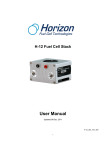
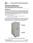
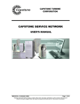
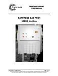
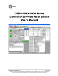
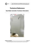
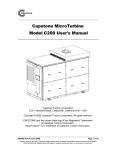
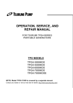
Capstone
Capstone Turbine Corporation • 21211 Nordhoff Street • Chatsworth • CA 91311 • USA
Telephone: (818) 734-5300 • Facsimile: (818) 734-5320 • Website: www.microturbine.com
Technical Reference
Gaseous System Technical Information
Introduction
This document provides product information for Capstone Turbine Corporation®
MicroTurbines operating on approved low-pressure and high-pressure gaseous fuels. Fuels
can vary in physical composition, higher heating (HHV) value and contaminant limitations.
See the MicroTurbine Fuel Requirements Technical Reference 410002 for further details.
Fuel system types covered in this document are: High/Low Pressure Natural Gas
(HPNG/LPNG), Landfill/Digester or Biogas, and Sour Gas. These types are collectively
referred to as: High Pressure and Low Pressure Natural Gas systems. High Pressure
Natural Gas descriptions apply to both stationary and hybrid electric vehicle (HEV) models.
Model C30 Natural Gas systems are available in several packages: standard, open, industrial
or Small Industrial Package (SIP) models. Model C60 systems are available only in the
Large Industrial Package (LIP).
Available configurations for low-pressure and high-pressure systems are shown below:
Standard or Open Package
Industrial Package
Small Industrial Package (SIP) or HEV
Large Industrial Package (LIP) – C60 only
410037-001 Rev B (January 2006)
Page 1 of 15
This information is proprietary to Capstone Turbine Corporation. Neither this document nor the information contained herein shall be copied, disclosed to others, or used for any
purposes other than the specific purpose for which this document was delivered. Capstone reserves the right to change or modify without notice, the design, the product
specifications, and/or the contents of this document without incurring any obligation either with respect to equipment previously sold or in the process of construction.
Capstone Turbine Corporation • 21211 Nordhoff Street • Chatsworth • CA 91311 • USA
Technical Reference: Gaseous System Technical Information
High Pressure Gas System Components
High-pressure gaseous fuel components (C60 – Large Industrial Package shown) are
identified below:
NOTE
Component descriptions are provided in the Components Description
Technical Reference Manual (410012).
Smart Proportional
Valve (SPV)
To Fuel
Manifold
Injector Lines
Gaseous
Filter
Electrical Fuel
Shutoff Valve
Fuel Inlet
Top View
Injector Tube
Connections
To Fuel
Manifold
Electrical Fuel
Shutoff Valve
Smart
Proportional Valve
(SPV)
Side View
410037-001 Rev B (January 2006)
Page 2 of 15
This information is proprietary to Capstone Turbine Corporation. Neither this document nor the information contained herein shall be copied, disclosed to others, or used for any
purposes other than the specific purpose for which this document was delivered. Capstone reserves the right to change or modify without notice, the design, the product
specifications, and/or the contents of this document without incurring any obligation either with respect to equipment previously sold or in the process of construction.
Capstone Turbine Corporation • 21211 Nordhoff Street • Chatsworth • CA 91311 • USA
Technical Reference: Gaseous System Technical Information
Low Pressure Gas System Components
Low-pressure fuel system components (C30 - Standard Package shown) are identified below:
NOTE
Component descriptions are provided in the Components Description
Technical Reference Manual (410012).
Heat
Exchanger
Vacuum
Pressure Switch
Rotary Flow
Controller (RFC)
RFC Exit
Pressure
Transducer
Inlet Gas
Connection
Smart
Proportional
Valve (SPV)
Screen Inlet
Fuel Filter
Electrical Fuel
Shutoff Valve
Premix Fuel Lines to Injectors
Pilot Fuel Lines to Injectors
Pilot Injector
Solenoids
Fuel Manifold
Fuel from SPV
Premix
Solenoid
Exit Pressure
Transducer
410037-001 Rev B (January 2006)
Page 3 of 15
This information is proprietary to Capstone Turbine Corporation. Neither this document nor the information contained herein shall be copied, disclosed to others, or used for any
purposes other than the specific purpose for which this document was delivered. Capstone reserves the right to change or modify without notice, the design, the product
specifications, and/or the contents of this document without incurring any obligation either with respect to equipment previously sold or in the process of construction.
Capstone Turbine Corporation • 21211 Nordhoff Street • Chatsworth • CA 91311 • USA
Technical Reference: Gaseous System Technical Information
System Operation
High-Pressure Natural Gas
A block diagram of a Model C30 high-pressure natural gas fuel system is shown below.
SCREEN
INLET
FILTER
FUEL
INLET
ELECTRICAL
SHUTOFF
SOLENOID
P
FUEL MANIFOLD
SPV
PILOT
INJECTOR
LINES
INJECTOR
SOLENOIDS
1
HIGH PRESSURE FUEL
OPTION KIT 507849-1XX
2
3
TURBINE
PREMIX
INJECTOR
LINES
1
2
3
A block diagram of a Model C60 high-pressure natural gas fuel system is shown below.
FUEL
INLET
SCREEN
INLET
FILTER
ELECTRICAL
SHUTOFF
SOLENOID
P
FUEL MANIFOLD
SPV
INJECTOR
SOLENOIDS
HIGH PRESSURE FUEL
OPTION KIT 507849-1XX
1
TURBINE
2
3
4
5
6
410037-001 Rev B (January 2006)
Page 4 of 15
This information is proprietary to Capstone Turbine Corporation. Neither this document nor the information contained herein shall be copied, disclosed to others, or used for any
purposes other than the specific purpose for which this document was delivered. Capstone reserves the right to change or modify without notice, the design, the product
specifications, and/or the contents of this document without incurring any obligation either with respect to equipment previously sold or in the process of construction.
Capstone Turbine Corporation • 21211 Nordhoff Street • Chatsworth • CA 91311 • USA
Technical Reference: Gaseous System Technical Information
Natural gas enters the MicroTurbine package inlet and is passed through a gaseous filtering
element to eliminate particulates from the fuel. Filtered fuel flows through an electrical fuel
shutoff valve, which is commanded on for operation. The fuel shutoff valve protects the
MicroTurbine by cutting off fuel to the MicroTurbine in case of a fault condition.
The Smart Proportional Valve (SPV) controls fuel flow into the fuel manifold, and subsequently
into the injectors, based on a software-controlled position command. Maximum fuel supply to
the injectors is delivered at a command of 80 percent valve position.
The fuel manifold contains electrically controlled solenoids, which directs fuel flow through the
injectors. The number of injectors depends on the MicroTurbine model. On a Model C30, four
solenoids control fuel flow into the three injectors – there are three pilot solenoids and a single
premix solenoid. On a Model C60, there are five solenoids - one solenoid activates injectors 1
and 2, the others individually turn on injectors 3, 4, 5 and 6.
410037-001 Rev B (January 2006)
Page 5 of 15
This information is proprietary to Capstone Turbine Corporation. Neither this document nor the information contained herein shall be copied, disclosed to others, or used for any
purposes other than the specific purpose for which this document was delivered. Capstone reserves the right to change or modify without notice, the design, the product
specifications, and/or the contents of this document without incurring any obligation either with respect to equipment previously sold or in the process of construction.
Capstone Turbine Corporation • 21211 Nordhoff Street • Chatsworth • CA 91311 • USA
Technical Reference: Gaseous System Technical Information
Low Pressure Natural Gas
A block diagram of a Model C30 low-pressure natural gas system is shown below (dotted line
for pressure transducer indicates this component has been eliminated in later models):
VACUUM
SWITCH
FUEL
INLET
SCREEN
INLET
FILTER
P
ELECTRICAL
SHUTOFF
SOLENOID
RFC
P
NOTE:
Transducer eliminated
in later SIP models
FUEL MANIFOLD
HEAT
EXCHANGER
SPV
PILOT
INJECTOR
LINES
INJECTOR
SOLENOIDS
1
LOW PRESSURE FUEL
OPTION KIT 507849-2XX
2
3
TURBINE
PREMIX
INJECTOR
LINES
1
2
3
Natural gas entering the MicroTurbine is monitored for fuel pressure by a protective vacuum
(pressure) switch. If close to vacuum conditions are detected, operation ceases and a 3024
LOW FUEL PRESSURE fault is reported. An inlet screen filter to the electrical shutoff valve
restricts larger fuel particulates from clogging the system. If a fault condition exists, the
electrical fuel shutoff valve closes to stop fuel flow into the MicroTurbine; otherwise it is
commanded open to maintain fuel flow to the MicroTurbine during system operation.
The Foil Bearing Rotary Flow Compressor (FB-RFC) compresses the low-pressure fuel
supply up to the required fuel system operating pressure. The RFC operates as a gas
compressor at low fuel rates and a flow control device at high fuel flow rates. The
compressed high-temperature gas from the RFC is pressure monitored and cooled via a heat
exchanger before entering the SPV.
The SPV and RFC work together to control fuel flow. At low power levels, the RFC operates
at a constant speed and the controlling orifice in the SPV meters fuel. At high power levels,
the SPV is commanded to a maximum open position, and the flow is metered by varying the
speed of the RFC.
A vacuum switch is present on the gas inlet to the fuel system to ensure that the fuel pressure
is nominally maintained above ambient pressure conditions. This protects the RFC from
operating under gas-starved conditions that could damage the foil bearings (i.e., the gas
supply is shut off during system operation).
The fuel manifold contains electrically-controlled solenoids, which direct injector fuel flow. On
earlier low-pressure configurations, exit pressure is monitored through a transducer mounted
on the fuel manifold. In later models (SIP configuration), this transducer has been eliminated.
Low Pressure natural gas systems may require additional considerations or fuel option kits to
deal with inlet fuel pressures above or below nominal pressures.
410037-001 Rev B (January 2006)
Page 6 of 15
This information is proprietary to Capstone Turbine Corporation. Neither this document nor the information contained herein shall be copied, disclosed to others, or used for any
purposes other than the specific purpose for which this document was delivered. Capstone reserves the right to change or modify without notice, the design, the product
specifications, and/or the contents of this document without incurring any obligation either with respect to equipment previously sold or in the process of construction.
Capstone Turbine Corporation • 21211 Nordhoff Street • Chatsworth • CA 91311 • USA
Technical Reference: Gaseous System Technical Information
Injector Operation
Model C30
The Model C30 MicroTurbine utilizes three pilot injector solenoids (1, 2 and 3), and a single
premix solenoid to control fuel flow to the engine.
Each injector delivers fuel from two points of entry – directly from the pilot
tube, or through the premix tube. The pilot tubes supply fuel directly into
the combustion chamber, mixing with air from the recuperator. The
premix tubes utilize air from the recuperator through swirl holes in the
injector, prior to entering the combustion chamber.
Pilot
Premix
Injector operation changes at different power levels (ISO corrected
generator power). Power levels for each injector switch point decrease by
approximately 2 kW due to hysterisis effects during offloading.
•
Below 7 kW, the MicroTurbine operates with a single pilot injector.
•
From 7 kW to 22 kW, all three pilot injectors are switched on.
•
Above 22 kW, all three pilot solenoids are turned off, and the
premix solenoid is switched on.
Air Mix
Swirl Holes
C30 Injector
To increase flame stability with medium or low BTU content fuels, the sequencing of the fuel
solenoids changes based on the BTU content value selected. For a BTU content setting of
medium, the system will light on three pilot injectors and switch to premix mode as noted
above. Medium BTU systems will never operate in single pilot mode. For a BTU content
setting of low, the system will light and always operate in premix mode. The pilot solenoids
will never be used. Refer to the BTU Content Switch section for information on this setting.
Model C60
The Model C60 MicroTurbine utilizes five injector solenoids, located on the fuel manifold for
controlling fuel flow into six injector ports of the engine.
Premix
Injectors 1 and 2 are always on and are controlled by a single solenoid.
Injectors 3 thru 6 are operated by separately controlled solenoids. The
C60 always operates in premix mode.
Injector operation changes at different power levels (ISO corrected
generator power). Power levels for each injector switch point decrease
by approximately 3 kW due to hysterisis effects during offloading.
•
The MicroTurbine initially lights using injectors 1 and 2 (one solenoid
operates both injectors).
•
Above 15 kW, third injector turns on (turns off at ~12 kW).
•
Above 26 kW, fourth injector turns on (turns off at ~23 kW).
•
Above 43 kW, fifth injector turns on (turns off at ~40 kW).
•
Above 54 kW, sixth injector turns on, and all six are in operation (turns off at ~51 kW).
410037-001 Rev B (January 2006)
Air Mix
Entrance
C60 Injector
Page 7 of 15
This information is proprietary to Capstone Turbine Corporation. Neither this document nor the information contained herein shall be copied, disclosed to others, or used for any
purposes other than the specific purpose for which this document was delivered. Capstone reserves the right to change or modify without notice, the design, the product
specifications, and/or the contents of this document without incurring any obligation either with respect to equipment previously sold or in the process of construction.
Capstone Turbine Corporation • 21211 Nordhoff Street • Chatsworth • CA 91311 • USA
Technical Reference: Gaseous System Technical Information
Fuel Selection and Utilization
Allowable Fuels
The MicroTurbine is capable of burning a wide variety of gaseous fuels to generate electrical
power. A Model C30 low BTU fuel system option can provide for operation from 13,000 (350)
to 26,100 kj/NM3 (760 BTU/scf). This option requires higher fuel gas supply pressures and is
not available in combination with the low-pressure fuel system. For more information
regarding fuels allowed on different system configurations, refer to the MicroTurbine Fuel
Requirements Technical Reference (410002).
Specifying Fuel Characteristics
As shipped, the MicroTurbine is configured for standard natural gas fuel. If gaseous fuels
with physical characteristics other than standard natural gas fuel are used, information on the
physical characteristics of these fuels may be entered into the system to ensure that:
a) Flame stability margins are maintained, and
b) NOx exhaust emissions are minimized.
Fuel Indices
The MicroTurbine incorporates fuel gas physical characteristics into the control functions in
the form of the fuel indices defined as follows:
NOTE
Index parameters must meet requirements stated in the MicroTurbine Fuel
Requirements Technical Reference (410002).
FUELI1 = SG *
1327
HHVvol
2
FUELI2 - (Not currently used on gaseous fuel systems)
where:
SG = fuel gas specific gravity, with respect to air
HHVvol = fuel gas higher heating value, BTU/scf
Fuel Index 1 (FUELI1) is a parameter related to the fuel density and energy content. If the
FUELI1 parameter entered differs by more than 15 percent from the index for the actual fuel
being burned, nuisance flameout or over-temperature faults may occur.
Setting adjustments may be entered through the display panel keypad, or remotely, through
the user interface port (UIP) upon commissioning of the system. Table 1 shows the values of
FUELI1 for common fuel gases.
Fuel Index 2 (FUELI2) is not currently used on gaseous fuel systems.
The specific gravity (SG) and higher heating value (HHVvol) of commercial natural gas fuels
may be obtained from the local natural gas supplier. Gas chromatographic analyses of noncommercial fuel gases commonly report calculated specific gravity and higher heating value.
410037-001 Rev B (January 2006)
Page 8 of 15
This information is proprietary to Capstone Turbine Corporation. Neither this document nor the information contained herein shall be copied, disclosed to others, or used for any
purposes other than the specific purpose for which this document was delivered. Capstone reserves the right to change or modify without notice, the design, the product
specifications, and/or the contents of this document without incurring any obligation either with respect to equipment previously sold or in the process of construction.
Capstone Turbine Corporation • 21211 Nordhoff Street • Chatsworth • CA 91311 • USA
Technical Reference: Gaseous System Technical Information
BTU Content Setting
As the energy content of fuel gas decreases, so does flame stability. To maintain acceptable
flame stability below 970 BTU/scf HHV on Landfill /Digester and Sour Gas Model C30
systems, adjustments in fuel system sequencing are required. The BTU Content switch
enables these adjustments.
System Settings
Menu
BTU Content
Variable BTU
<FUELI1>
Parameter Description
(BTU/scf HHV)
Format
Normal for 970 – 2516
Medium for 760 – 970
Low for 350 – 760
Normal
Medium
Low
FUELI1 as defined above
0.10 – 99.99
Default
Normal
1.00
Table 1. Fuel Indices for Common Fuel Gases
Specific
Gravity (w/
respect to air)
HHVvol High
Heating Value
(BTU/scf)
Natural Gas Baseline
0.613
1,039
1.00
Normal
Methane
0.554
1,013
0.95
Normal
Ethane
1.049
1,792
0.58
Normal
Propane
1.562
2,592
0.41
Normal
Digester gas (max)
0.959
672
3.74
Low
Digester gas (avg)
0.909
607
4.34
Low
Digester gas (min)
0.862
363
11.49
Low
Landfill gas (max)
1.004
674
3.90
Low
Landfill gas (avg)
0.973
496
6.96
Low
Landfill gas (min)
0.995
355
13.94
Low
Fuel Name
410037-001 Rev B (January 2006)
FUELI1
BTU Content
Switch
Page 9 of 15
This information is proprietary to Capstone Turbine Corporation. Neither this document nor the information contained herein shall be copied, disclosed to others, or used for any
purposes other than the specific purpose for which this document was delivered. Capstone reserves the right to change or modify without notice, the design, the product
specifications, and/or the contents of this document without incurring any obligation either with respect to equipment previously sold or in the process of construction.
Capstone Turbine Corporation • 21211 Nordhoff Street • Chatsworth • CA 91311 • USA
Technical Reference: Gaseous System Technical Information
If values of the specific gravity and/or higher heating value are not available, they may be
calculated from the gas composition. A sample calculation is provided in Table 2.
Table 2. Sample Calculation, Oil Wellhead Gas
1
Gas
Component
2
Symbol
5
6
7
3
4
Concentration
(SG)
HHVvol
(SG)
HHVvol
(Volume %) (Col 3 * Col 5) (Col 4 *Col 5)
(WRT Air) (BTU/Scf)
Hydrogen
H2
0.0695
325
-
-
-
Carbon
Monoxide
CO
0.9672
322
-
-
-
Methane
CH4
0.5541
1013
61%
0.338
618
Ethane
C2H6
1.0488
1792
26%
0.2727
466
Ethylene
C2H4
0.974
1613
-
-
-
Propane
C3H8
1.5624
2592
5%
0.0781
130
Propylene
C3H6
1.45
2336
-
-
-
N-Butane
C4H10
2.0666
3373
2%
0.0613
67
Iso-Butane
C4H10
2.0666
3365
-
-
-
N-Pentane
C5H12
2.4872
4017
1%
0.0249
40
Iso-Pentane
C5H12
2.4872
4007
-
-
-
Hyrogen Sulfide
H2S
1.1899
646
2%
0.0238
13
Carbon Dioxide
CO2
1.5284
-
3%
0.0459
-
Nitrogen
N2
0.9717
-
-
-
-
Oxygen
O2
1.1053
-
-
-
-
H2O
0.6215
-
-
-
-
Total
100%
0.8447
1334
Water Vapor
FUELI1 = 0.8447 *
1327
2
= 0.84
1334
410037-001 Rev B (January 2006)
Page 10 of 15
This information is proprietary to Capstone Turbine Corporation. Neither this document nor the information contained herein shall be copied, disclosed to others, or used for any
purposes other than the specific purpose for which this document was delivered. Capstone reserves the right to change or modify without notice, the design, the product
specifications, and/or the contents of this document without incurring any obligation either with respect to equipment previously sold or in the process of construction.
Capstone Turbine Corporation • 21211 Nordhoff Street • Chatsworth • CA 91311 • USA
Technical Reference: Gaseous System Technical Information
Installation Requirements
A main filter must be installed external to the MicroTurbine. A pressure regulator is usually
required to maintain steady fuel pressure at the MicroTurbine inlet. The inlet pressure must
remain at or above the minimum requirement during load and during cold (maximum fuel
flow) conditions.
Fuel Option Kits available from Capstone provide the necessary manual fuel isolation valve,
external fuel filter, purge valve and pressure regulator needed for a standard installation.
Contact Capstone Technical Support for details on the Fuel Option kits specified below:
Part
Number
Description
Remarks
507849-1XX High Pressure External Gaseous Fuel Kit
Pressure regulator, gauge,
manual shutoff valve and filtration
507849-2XX Low Pressure External Gaseous Fuel Kit
Manual shutoff valve and filtration
508604-1XX Sour Gas External Gaseous Fuel Kit
Pressure regulator, gauge,
manual shutoff valve and filtration
Commissioning the System
The MicroTurbine inlet pressure requirements are defined in Tables 3 and 4. The inlet fuel
gas supply must be maintained at minimum pressure at the maximum flow rate for proper
operation. An adequate fuel supply pressure without pressure loss at high flow rates is
ESSENTIAL for proper MicroTurbine operation.
Due to inlet pressure requirements, many applications require external compressors.
Capstone can provide optional Fuel Gas Booster (FGB) kits that can be operated using
MicroTurbine power for Stand Alone installations. Refer to the Capstone Fuel Gas Booster
Installation Instructions (410016) for details.
Special Biogas fuel processing considerations in meeting liquid fuel particulate requirements
can be found in the Landfill/Digester Biogas Gas Usage (Biogas) Application Guide (480002).
410037-001 Rev B (January 2006)
Page 11 of 15
This information is proprietary to Capstone Turbine Corporation. Neither this document nor the information contained herein shall be copied, disclosed to others, or used for any
purposes other than the specific purpose for which this document was delivered. Capstone reserves the right to change or modify without notice, the design, the product
specifications, and/or the contents of this document without incurring any obligation either with respect to equipment previously sold or in the process of construction.
Capstone Turbine Corporation • 21211 Nordhoff Street • Chatsworth • CA 91311 • USA
Technical Reference: Gaseous System Technical Information
Table 3. Gaseous Fuel Supply Pressure and Temperature Requirements
Supply Pressure in kPa (Gage (psig))
System
Supply Temperature in °C (°F)
LSL
USL
LSL
USL
C30 HP
379 (55)
(Note 2)
414 (60)
(Notes 2,3)
Note (4)
50 (122)
C30 LP
1.4 (0.20)
103 (15)
Note (4)
50 (122)
C30 SG
379 (55)
(Note 2)
414 (60)
(Note 2)
Note (4)
C30 L/DG
(Note 3)
(Note 3)
Note (4)
50 (122)
C60 HP
517 (75)
552 (80)
Note (4)
50 (122)
C60 HP/ ICHP
517 (75)
552 (80)
Note (4)
50 (122)
C60 LP (Note 1)
3.4 (0.50)
103 (10)
Note (4)
50 (122)
3.4 (0.50)
103 (10)
Note (4)
50 (122)
C60 LP/ ICHP (Note 1)
50 (122)
Notes:
(1) Low pressure gas can be used when C60 HP, C60 HP ICHP is integrated with Capstone
Integrated Fuel System Optional Accessory.
(2) Fuels with Calorific Value greater than Natural Gas Range or Sour Natural Gas Range may
require lower inlet pressures, down to 310 kPa (45 psig).
(3) This item is dependent upon the fuel Calorific Value as noted in Table 4.
(4) This value must be the highest of 0 °C (32 °F), or 10 °C (18 °F) above the fuel dew point
temperature at the Fuel Supply Pressure Maximum noted in this table.
Table 4. L/DG Fuel Supply Pressure Requirements
Calorific Value (HHV)
[MJ/m3 (Btu/ft3)]
Supply Pressure
[kPa Gage (psig)]
LSL
USL
LSL
USL
26.1 (700)
38.4 (1,030)
345 (50)
379 (55)
22.4 (600)
26.1 (700)
345 (50)
414 (60)
18.6 (500)
22.4 (600)
379 (55)
448 (65)
16.8 (450)
18.6 (500)
414 (60)
483 (70)
14.9 (400)
16.8 (450)
448 (65)
517 (75)
12.1 (325)
14.9 (400)
483 (70)
552 (80)
410037-001 Rev B (January 2006)
Page 12 of 15
This information is proprietary to Capstone Turbine Corporation. Neither this document nor the information contained herein shall be copied, disclosed to others, or used for any
purposes other than the specific purpose for which this document was delivered. Capstone reserves the right to change or modify without notice, the design, the product
specifications, and/or the contents of this document without incurring any obligation either with respect to equipment previously sold or in the process of construction.
Capstone Turbine Corporation • 21211 Nordhoff Street • Chatsworth • CA 91311 • USA
Technical Reference: Gaseous System Technical Information
Diagnostic Faults
Detailed explanation of all gas-related diagnostic faults is available in the Model C30
Troubleshooting Guide (430000), and Model C60 Troubleshooting Guide (430013). Some
of the more common fuel system faults that may appear are listed below.
Sensor Faults
Fault No.
3024
Fault Description
LOW FUEL PRESSURE
SSL
3
Isolation Message
Internal Fault
3026
LOW FUEL AIR PRESSURE
3
Internal Fault
3027
HIGH FUEL AIR PRESSURE
3
Internal Fualt
3029
RFC AIR ASSIST FAILURE
3
Fuel Fault
3031
RFC LOW FUEL PRESSURE
3
Fuel Fault
SSL
3
Isolation Message
Internal Fault
3
Internal Fault
SSL
3
Isolation Message
Internal Fault
Package Faults
Fault No.
5000
Fault Description
FUEL SUBSYSTEM
5001
NO FUEL DEVICE
Operational Faults
Fault No.
6006
Fault Description
FAIL TO LIGHT
6009
OVERTEMP
3
Internal Fault
6010
HIOVERTEMP
3
Internal Fault
6011
FLAMEOUT_START
3
Internal Fault
6012
FLAMEOUT_LOAD
3
Internal Fault
410037-001 Rev B (January 2006)
Page 13 of 15
This information is proprietary to Capstone Turbine Corporation. Neither this document nor the information contained herein shall be copied, disclosed to others, or used for any
purposes other than the specific purpose for which this document was delivered. Capstone reserves the right to change or modify without notice, the design, the product
specifications, and/or the contents of this document without incurring any obligation either with respect to equipment previously sold or in the process of construction.
Capstone Turbine Corporation • 21211 Nordhoff Street • Chatsworth • CA 91311 • USA
Technical Reference: Gaseous System Technical Information
Maintenance Items
Scheduled maintenance intervals for component parts are summarized in the MicroTurbine
Standard Maintenance Schedule (440000).
Related Documentation
The following table lists applicable Capstone documentation.
Document
No.
Document Title
400000
Capstone MicroTurbine Users Manual
410002
Capstone MicroTurbine Fuel Requirements Technical Reference
410012
Capstone Components Description Technical Reference
410013
Capstone Remote Monitoring System (Users Edition) Technical Reference
410016
Capstone Fuel Gas Booster Installation Instructions
430000
Capstone Model C30 Troubleshooting Guide
430002
Capstone Model C30 Service Manual
430013
Capstone Model C60 Troubleshooting Guide
430017
Capstone Model C60 Service Manual
440000
Capstone MicroTurbine Standard Maintenance Schedule Work Instructions
480002
Capstone Landfill/Digester Gas Usage (Biogas) Application Guide
410037-001 Rev B (January 2006)
Page 14 of 15
This information is proprietary to Capstone Turbine Corporation. Neither this document nor the information contained herein shall be copied, disclosed to others, or used for any
purposes other than the specific purpose for which this document was delivered. Capstone reserves the right to change or modify without notice, the design, the product
specifications, and/or the contents of this document without incurring any obligation either with respect to equipment previously sold or in the process of construction.
Capstone Turbine Corporation • 21211 Nordhoff Street • Chatsworth • CA 91311 • USA
Technical Reference: Gaseous System Technical Information
Capstone Technical Information
If questions arise regarding Natural Gas operation for your Capstone MicroTurbine, please
contact Capstone Turbine Technical Support for assistance and information.
Capstone Technical Support
Toll Free Telephone: (877) 282-8966
Service Telephone: (818) 407-3600 • Fax: (818) 734-1080
E-mail: [email protected]
Capstone Technical Support (Japan)
Service Telephone: (818) 407-3700 • Fax: (818) 734-1080
E-mail: [email protected]
Capstone Turbine Corporation
21211 Nordhoff Street • Chatsworth, CA 91311 • USA
Telephone: (818) 734-5300 • Fax: (818) 734-5320
Website: www.microturbine.com
410037-001 Rev B (January 2006)
Page 15 of 15
This information is proprietary to Capstone Turbine Corporation. Neither this document nor the information contained herein shall be copied, disclosed to others, or used for any
purposes other than the specific purpose for which this document was delivered. Capstone reserves the right to change or modify without notice, the design, the product
specifications, and/or the contents of this document without incurring any obligation either with respect to equipment previously sold or in the process of construction.