1
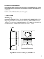
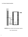
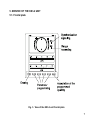
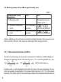
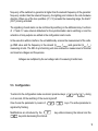
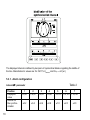
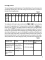
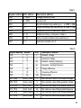
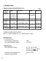
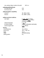
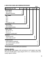
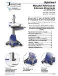
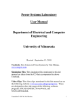
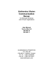
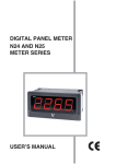
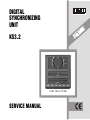
DIGITAL SYNCHRONIZING UNIT D E I F KS3.2 I T R E C 144 x 144 x 77 mm SERVICE MANUAL 1 CONTENTS 1. APPLICATION ........................................................................................ 3 2. DELIVERY SPECIFICATION ................................................................. 3 3. BASIC SAFETY REQUIREMENTS AND USER´S SAFETY ................. 4 4. INSTALLATION ...................................................................................... 5 4.1. Fixing way ........................................................................................ 5 4.2. Scheme of external connections ..................................................... 6 5. SERVICE OF THE KS3-2 UNIT ............................................................. 7 5.1. Frontal plate ..................................................................................... 7 5.2. Working modes of the KS3-2 synchronizing unit ............................. 8 5.2.1. Measuring functions of the KS3-2 ............................................. 8 5.3. Configuration .................................................................................... 9 5.3.1. Alarm configuration .................................................................... 10 5.3.2. Interface configuration ................................................................ 12 6. RS-485 INTERFACE .............................................................................. 13 6.1. Description ....................................................................................... 13 6.2. Register map .................................................................................... 14 7. TECHNICAL DATA ................................................................................ 16 8. EXECUTION CODES AND ORDERING PROCEDURE ........................ 19 9. MAINTENANCE AND WARRANTY ...................................................... 20 2 1. APPLICATION The KS3-2 digital synchronizing unit is destined to synchronize generators during their coupling in parallel to the network or other generators working at the rated 50 or 60 Hz frequency. The full synchronization is obtained at the moment when follows the equalization of the voltage, frequency and phase angle. The phase angle difference of signals from the generator and the network is indicated by the synchroscope which has the shape of a circle of diodes.The voltage difference between the generator and the network in the -20%...0...+20% interval is indicated by the upper horizontal line ∆V, which the zero in the middle. The lower horizontal diode line with the zero in the middle, designated ∆f, indicates the frequency difference of signals from generator and the network in the -10%...0...+10% (45...55 Hz) interval. The green diodes on horizontal bargraphs and diodes inside the circle are lighting on the unit frontal plate at the moment when the synchronization is reached. The unit includes two relay outputs. One of the relay signal indicates the moment when we reach the synchronization. The second relay signals the measuring range exceeding of the chosen quantity. 2. DELIVERY SPECIFICATION The KS3-2 synchronizing unit set includes: - KS3-2 synchronizing unit ......................................... 1pc - screw holders fixing the unit on a panel ................. 4pcs - service manual ........................................................ 1pc - warranty card ........................................................... 1pc 3 3. BASIC REQUIREMENTS AND USERS SAFETY KS3-2 synchronizing units are intended to be installed in panels, switchboards and cubicles They are in conformity with IEC 1010-1+A1 (1996) safety requirements. Remarks concerning safety: The unit installation should be carried out by a qualified staff. One must consider all accessible aspects of the protection. The instrument lefs the factory in perfect condition regarding technical safety. In order to maintain this condition and to ensure safe operation, the user must comply with indications and markings contained in the following instructions: Before mounting, ensure that the operating voltage and mains voltage set are the same, and then proceed with installation. The power supply must be connected as shown in the relevant diagram. Before the switching on, check the correctness of meter connections Before any maintenance and/or repairs, whenever the instrument must be opened, it must be disconnected from all power sources. Maintenance and/or repairs must be carried out only by qualified authorized personnel. If there is ever the suspicion that safe use is no longer possible, the instrument must be taken out of service and precautions taken against accidental use. Operation is no longer safe when: - there is clearly visible damage, - the instrument no longer functions, - after lengthy storage in unfavorable conditions, - after serious damage incurred during transport. Operator safety The instrument described in this service manual is intended for use by properly trained staff only. Maintenance and/or repairs must be carried out only by authorized personnel. For proper, safe use of the instrument and for maintenance and/or repairs, it is essential that the persons instructed to carry out these procedures follow normal safety precautions. 4 Precautions in case of breakdowns If it is suspected that the instrument is no longer safe, for example due to damage incurred during transport or use, it must be taken out of service and precautions taken to prevent any accidental use. Contact authorized technicians for checks and any repairs. 4. INSTALLATION 4.1. Fixing way One should cut-out a hole of 138+0.5 x 138+0.5 mm dimensions in the panel and fix the synchronizing unit by means of four screw holders. The unit housing, which overall dimensions are 144 x 144 x 77 mm, is made of self-extinguishing plastics. The screw terminal strips enable the connection of external conductors which maximal cross-section is 2.5 mm2. Fig. 1. Overall dimensions and fixing way of the KS3-2 unit 5 4.2. Scheme of external connections CAUTION: before connection check the phase sequence Fig. 2. Connection scheme 6 5. SERVICE OF THE KS3-2 UNIT 5.1. Frontal plate Fig. 3. View of the KS3-2 unit frontal plate 7 5.2. Working modes of the KS3-2 synchronizing unit. Table 1 Working mode calling Designation Entry Exit 1. Measuring mode Through the entry into another mode 2. Parameter configuration In the configuration mode 3. Interface configuration mode procedure In the configuration procedure or after the last parameter or after the last parameter After its switching on, the unit makes an autotest and lights all diodes. This sequence occurs after each start of the unit. The measuring mode begins after carrying out tests. 5.2.1. Measurement functions of KS3-2. The KS3-2 synchronizing unit ensures the measurement of: difference of RMS voltage and frequency in measuring circuits of the network (Unetwork1, fnetwork1) and the generator (Ugen, fgen) ∆ U= U L 2 − U L1 ⋅100 U L1 ∆ f= f L 2 − f L1 ⋅100 f L1 and the phase angle (ϕ). A lighting point on each bargraphs informs about the value of the given parameter. The synchroscope enables the identification of the phase rotation direction, at ∆ f < 5% of the network frequency. The lighting point of the synchroscope rotates in the clockwise direction when the 8 frequency of the switched on generator is higher than the network frequency. At the generator frequency smaller than the network frequency, the lighting point rotates in the anti-clockwise direction. When one of the two quantities (∆ f, ∆ V) exceeds the measuring range, the Alarm2 (OUT) is being activated. The signalling of each alarm can be confirmed by switching on the attributed relay. Functions of ∆ f and ∆ V value interval atributions for the synchronization alarm switching on and the activation of relay outputs are settled in the configuration alarm mode. In the execution with an interface, the unit additionally ensures the measurement of the voltage RMS value and the frequency in the network (Unetwork, fnetwork) and generator (Ugen, fgen) measuring circuits. The KS3-2 synchronizing unit also enables the measurement of minimal and maximal voltages and frequencies. Voltages are multiplied by the set voltage ratio of measuring transformers. 5.3. Configuration To enter into the configuration mode one should press two keys: ca 3 seconds, till the switching of the sound signal off. One choose the parameter by means of signalled by flashing. Modifications are introduced by the key while decreasing the interval. and during keys. The active parameter is key while increasing the interval and the 9 The displayed interval is defined by two pairs of symmetrical diodes regarding the middle of the line. Manufacturer′s values are: for ∆U=1% Unetwork and for ϕ = ±2° (el.) 5.3.1. Alarm configuration Table 2 Interval ∆ ∆V parameter Position Displayed value Interval for the synchronization 10 1 <-2,2> 2 <-4,4> 3 <-6,6> 4 <-8,8> ±0.2 ±0.4 ±0.6 ±0.8 5 6 7 <-10,10> <-12,12> <-14,14> ±1.0 ±2.0 ±3.0 Interval ϕ parameter The range changes through the displacement of two lighted diodes on the synchroscope circle symmetrically regarding the 0° point. While moving from this point away, one causes the transition to the succeeding range. Table 3 Range 1 2 3 4 5 6 7 8 9 Interval 359...1 358...2 357...3 356...4 355...5 354...6 353...7 352...8 351...9 for the synchronization The configuration for the alarm output is carried out by 10 350...10 keys, by choosing key and the screen of the appropriate alarm. The relay operation is activated by the released by the key. The lighting of diodes in the alarm screen corresponds suitably to this. When the relay is not assigned, the alarm is only signalled by lighting. This concerns both the alarm synchronization and the measuring range exceeding. Marking the green diodes on the synchroscope circle, we set on the bargraph the automatic synchronization switching on after a supply voltage decay. The parameter switching off causes a lack of reaction to the synchronization moment. In order to activate the process one must enter into the configuration procedure and next, without changing the setting, come back into the measuring mode. Table 4 Range Synchronization alarm, modification range of voltage difference 0.2...1 [%] m.v. 1...10 (for the interface) 1 (step 0.2 [%] m.v.) 1...3 [%] m.v. 11...13 (for the interface) (step 1 [%] m.v.) Synchronization alarm, angle modification range 1...10 [°] m.v. = measured value Remarks / Description Manufacturer′′s value Parameter name 2 11 5.3.2. Interface configuration After pressing in the alarm mode we are configuring the RS-485 interface. The interface has got a constant 9600 kBit/s baud rate. The device′s address (1...10) is modified on the ∆V bargraph. To differentiate in the interface mode, the green diodes are constantly lighted on the bargraphs and we read out the value from the graduation. Fig. 5. Working modes of the KS3-2 unit. 12 6. RS-485 INTERFACE 6.1. Description 32 devices can work on one bus in the RS-485 standard. Interface sockets ( 2 x DB9) are situated at rear of the housing. One must use a screened strand to make the connection. The screening is necessary and the length of the installation can not exceed 1200 m. The hardware configuration defines the device number, the baud rate and parameters of the communication port. Fig. 6. Connection way of the KS3-2 interface. Device number: Baud rate: Working mode: where: 1....10 9600 kBit/sec 1...6 (8N1, 7E1, 7O1, 8N2, 8E1, 8O1) N - no parity E - even parity O - odd parity An asynchronous character communication protocol MODBUS is used in the device. This protocol is a standard taken by producers of industrial controllers for the asynchronous, character exchange of information between devices of measuring and control systems. 13 It possesses such features as: - simple access rule to the bus, based on the master-slave principle, - safeguard of transmitted messages against errors, - confirmation of remote command execution and signalling of errors, - efficient mechanisms to secure against the system suspension, - to take advantage of asynchronous character transmission. The information unit is the frame in ASCII or RTU code. 6.2. Register map Data are located in 16-bit or 32-bit registers in the KS3 - synchronizing unit. Process variables and meter parameters are located in the register address space in the way depended on the variable value type. Bits in the 16-bit register are numbered from the youngest to the oldest (b0 - b15). 32-bit registers include numbers of float type in the IEEE-745 standard. The register map has been divided into following areas: Address range Value type Description 4000 - 4006 Integer (16 bits) The value is located in one 16-bit register. The table 5 includes the register description. Registers can be read out and written. 7500 - 7518 Float (32 bits) The value is located in one 32-bit register. The table 6 includes the register description. Registers can only be read out. Contents of 16-bit registers with addressses from 4000 to 4007. 14 Table 5 Register address Unit, address 4000 1...4000 Description address Voltage transformer ratio 4001 0...9999 Access code 4002 0.1 Synchronization relay switching on 4003 0.1 Range exceeding relay switching on 0 - OFF, 1 - ON 4004 0...13 Settlement of the ∆V interval acc. table 4 4005 0...10 Settlement of the ϕ interval acc. table 4 4006 0...10 Delay of synchronization alarm switching on 4007 0.1 Automatic activation A1_0 0 - OFF, 1 - ON Table 6 Register address 7500 Symbol U1 Unit V Description address Network voltage 7501 U2 V Generator voltage 7502 f1 Hz Network working frequency 7503 f2 Hz Generator working frequency 7504 ∆U % Voltage difference 7505 ∆f % Frequency difference ∆ϕ ° (el) 7506 Phase angle 7507, 7508 minU1, maxU1 V Min. and max. value of the network voltage 7509, 7510 minU2, maxU2 V Min. and max. value of the generator voltage 7511, 7512 minf1, max f2 Hz Min. and max. value of the network frequency 7513, 7514 minf2, maxf2 Hz Min. and max. value of the generator frequency 7515, 7516 min∆U, max∆U % Min. and max. value of the voltage difference 7517, 7518 min∆f, max∆f % Min. and max. value of the frequency difference 15 7. TECHNICAL DATA • Measuring ranges and admissible basic errors Measured quantity Voltage Ui* Range 100.0 V (Ku = 1) 110.0 V (Ku = 1) 230.0 V (Ku = 1) 400.0 V (Ku = 1) Frequency f* 15.0...500.0 Hz Voltage difference -20...0...20% Frequency difference -10...0...10% Phase angle 0...360° Table 7 Basic error Notes Resolution ±(0.2% m.v. +0.1% of range Ku=1...4000 (max 400 kV) - ± 0.5% m.v. +2d - ± 0.5% of range +1 diode 0.6% Unetwork ± 0.2% of range +1 diode ± 1° 0.3% fnetwork 5°, 2°, ϕ < 3° * quantities accessible through the interface where: Ku = voltage transformer ratio, m.v. = measured values, d = digit • Additional errors in % of the basic error: - from the fraquency of input signal - from ambient temperature changes • 16 Measuring inputs - phase-to-phase input voltage < 50% < 50%/10 °C Un = 100, 110, 230, 400 V frequency = 15...45...65...500 Hz sinusoidal signal (TDH ≤8%) - momentary overload capacity (5 sec) 2Un (max. 1000 V) - admissible voltage peak factor 2 • Interface RS-485 - baud rate - protocol • Relay outputs - relays - load capacity - life time depending on cosϕ • Regarding field - synchroscope - differential voltmeter - differential frequency meter • Supply - supply voltage • Power consumption - supply voltage - voltage circuit • Reaction to decays and supply recoveries • Safety requirements acc. IEC 1010-1+A1 (1996) - insulation ensured by the housing - insulation between circuits - installation category - pollution degree 9600 MODBUS, ASCII, 8N1, ASCII 7E1 ASCII 701, RTU 8N2, RTU 8E1, RTU 801 voltage less make contacts 250 V~ / 0.5 A~ in the AC1 category: 1.5 x 10⁵, cosϕ = 1 105, cosϕ = 0.4, 250 V a.c. circle with 72 diodes bargraphs with 68 diodes and the zero in the middle bargraphs with 68 diodes and the zero in the middle 18...30 V d.c. a.c., 40...400 Hz 85...250V d.c. a.c., 40...400 Hz ≤ 12 VA ≤ 0.5 VA Data and state preservation of the synchronization unit in case of any decay (battery support). Continuation of unit operation after the supply recovery. double basic III 2 17 - max. working voltage in relation to the earth IP40 IP10 • Electromagnetic compatibility: - immunity - emission EN - 5082-2 (1996) EN - 50081-2 (1996) • Rated operational conditions - input signal - ambient temperature - air relative humidity - external magnetic field Housing - frontal dimensions - panel cut-out - depth - weight - working position 18 600 V a.c. • Housing protection degree - from the frontal side - from the rear side 0...0.01...1.2Un, for voltage frequency 15...45...65...500 Hz sinusoidal (THD ≤ 8%) 0...23...55° 25...95% (condensation inadmissible) 0...40...400 A/m 144 x 144 mm 138+0.5 x 138+0.5 mm 77 mm 800 g (with packing) any 8. EXECUTION CODES AND ORDERING PROCEDURE Synchronizing unit - KS3 X Kind of display: - digital displays - bargraphs (diode lines) 1 2 Input voltage: - 100 V - 110 V - 240 V - 400 V - on request, acc. order* XX X Table 8 X XX X 01 02 03 04 XX Digital output: - without interface - with an RS-485 interface Supply voltage: - 85...250 V d.c. a.c. - 24 V d.c. a.c. - on request, according order* Execution: - standard execution - custom-made execution* Acceptance tests: - without additional requirements - with a quality inspection certificate - other requirements* 0 1 0 1 X 00 XX 0 1 X * The execution code will be settled by the manufacturer ORDERING EXAMPLE Code: KS3-2-04-1-0-00-1 means: a KS3 synchronizing unit, with bargraphs, input voltage: 400V, with an RS-485 interface, supply voltage 85...250 V d.c. a.c., standard execution, with a quality inspection certificate. 19 9. MAINTENANCE AND WARRANTY KS3-2 synchronizing unit does not required any periodical maintenance. In case of some incorrect unit operation: 1. In the period of 12 months from the date of purchase: One should take the meter down from the installation and return to the LUMELs Quality Control Dept. If the unit has been used in compliance with the instructions, LUMEL S.A. warrants to repair it free of charge. 2. After the warranty period: One should turn over the unit to repair in a certified service workshop. The disassembling of the unit housing causes the cancellation of the granted warranty. Spart parts are available for the period of 10 years from the date of purchase. LUMEL S.A. reserves the right to make changes in design and specifications of any products as engineering advances or necessity requires. 20 NOTE 21 SALES PROGRAM 1. DIGITAL AND BARGRAPH PANEL METERS 2. MEASURING TRANSDUCERS 3. ANALOG PANEL METERS (DIN INSTRUMENTS) 4. CONTROLLERS 5. PEN, DOT AND SCREEN RECORDERS 6. POWER CONTROL UNITS and INVERTERS 7. CAR INDICATORS 8. MEASUREMENT ACCESSORIES (shunts, sensors, C. T.) 9. MEASURING SYSTEMS (HEAT, ENERGY, CONTROL, etc.) 10.CUSTOM-MADE PRODUCTS 11.PRESSURE CASTINGS 12.TOOLS QUALITY PROCEDURES: According ISO 9001 international requirements. ISO certificate granted by KEMA Registered Quality. November 2001 Lubuskie Zak³ady Aparatów Elektrycznych LUMEL S.A. ul. Sulechowska 1 65-950 Zielona Góra, POLAND tel. (48-68) 329 51 00 (exchange) Export Department: fax: (48-68) 329 51 01 tel. or fax (48-68) 325 40 91 e-mail: [email protected] e-mail: [email protected] http//www.lumel.com.pl 22