1
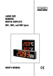
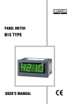
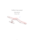
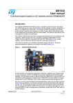
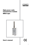
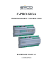
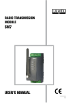
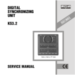
RS-485/CAN CONVERTER PD7 type USER’S MANUAL RS-485/CAN CONVERTER PD7 type CONTENTS: 1. APPLICATION........................................................................... 5 2. SET OF PD7 CONVERTER...................................................... 6 3. CONVERTER EXTERNAL DESCRIPTION.............................. 6 4. INSTALLATION......................................................................... 7 4.1. External converter connections......................................... 7 4.2. Setting of converter parameters........................................ 9 4.3. Assembly of PD7 converter............................................. 15 4.4. Requirements for terminal connections........................... 16 4.5. Optoisolation................................................................... 16 5. DESCRIPTION OF PD7 CONVERTER OPERATION............ 17 6. TECHNICAL DATA................................................................. 18 7. EXECUTION CODES.............................................................. 20 8. MAINTENANCE AND GUARANTEE...................................... 21 December 2006 - KZ 1314/06 1. APPLICATION The PD7 converter is a device linking the RS-485 bus with the CAN network. It has two interfaces: RS-485 and CAN 2.0A. The first serves to link devices taking advantage of the asynchronous character transmission (MODBUS protocol, etc.) with the RS-485 bus on which they are working. The second is the interface to the network, on which devices with the CAN 2.0A protocol (11-bit identifier) are working. The RS-485 standard allows to create a resistant bus against disturbances, on which 32 devices can work ( transmitters and receivers). The bus can be of 1200 m long. CAN 2. 0A (Controller Area Network) is an effective serial transmission protocol of multi-master type, working in real time and it offers built-in transmission correctness protections. Fig.1 Block diagram of an exemplary measuring system with the PD7 converter. The both standards have application in many control and measuring devices such: controllers, meters, transducers, a.s.l. The exemplary structure of a control and measuring system taking advantage of this converter is presented on the fig.1. 2. SET OF PD7 CONVERTER The set of PD7 converter includes: PD7 converter 1 pc Configurator wire 1 pc PD7 user’s manual 1 pc Guarantee card 1 pc Configurator program 1 pc (on a 3.5” diskette) 3. CONVERTER EXTERNAL DESCRIPTION The converter external appearance is presented on the fig.2. Terminal strip of the supply line Green LED diode (supply) Red LED diode (RS-485 bus) Yellow LED diode (CAN bus) DIN rail DB9 junction (CAN bus/configurating junction) terminal strip of the RS-485 bus Fig.2. Appearance of the PD7 converter frontal plate The casing of the device is made of plastics. The connector has two disconnectable terminal strips which enable a handy connection of wires. On the frontal plate there are three lighting LED diodes signalling the device working states and the DB9 connector, which is a normal device working renders accessible the converter service wire to the CAN bus, however during the converter configuration it fulfils the role of a connector for the configuration enabling the setting of transmission parameters being attended by the converter. 4. INSTALLATION 4.1. External converter connections The description of external signals accessible on terminals and the converter DB9 junction are presented on fig. 3. and in the tables 1 and 2. Table 1. Description of PD7 converter terminals Terminal Nr 6, 7 1 2 3 Terminal description Converter supply: 24 V a.c./d.c. or 230 V a.c. GND line of the RS-485 interface A line of the RS-485 interface B line of the RS-485 interface Table 2. Description of DB9 connection pins (socket of CAN interface) Terminal Nr 1 2 3 7 Terminal description Line of impulse slope perturbance suppression CAN LOW line of the CAN interface CAN GND line of the CAN interface CAN HIGH line of the CAN interface Fig. 3. External connections of PD7 converter ! ATTENTION ! The DB9 junction renders accessible also other signals used ONLY during the converter programming by means of the configurator wire and configurating program. There are successively: 4 - TXD signal 5 - RxD signal 8 - GND signal 9 - VCC (+5 V) signal The connecting junction of the CAN interface CANNOT render these signals accessible. In case of high baud rates of the CAN bus (over 125 kbit/s) CAN impulses increase the perturbance emission. These perturbances can be suppressed by shorting pins Nr 1 and 3 (in DB9 junction connecting PD7 converter to the bus). At smallest baud rates (up to 125 kbit/s) , shortening of pins 1 and 3 in the DB9 junction is not necessary. Information on the rate at which the shortening of pins 1 and 3 are required is included in the table 3. The way to make connections of pins 1 and 3 is shown on the fig. 4. Fig. 4. Way of making connections of pins 1 and 3 for rates higher than 125 kbit/s Table 3: State of DB9 junction pins 1 and 3 connection for different baud rates of the CAN bus. Baud rate of CAN bus (kbit/s) Shortening of pins 1 and 3 10, 20, 25, 50, 100 No required 125, 250, 500, 800, 1000, Required Ends of the CAN bus should be closed by resistor terminators. Their values depend first of all on the bus length. The set of terminator values depending on the bus length is presented in the table 4. Table 4. Set of terminator values depending on the CAN bus length Bus length [m] Resistance closing the bus Max. data transmission rate 0 - 40 124 1 Mbit/s at 40 m 40 - 300 127 500 kbit/s at 100 m 300 - 600 150 to 300 100 kbit/s at 500 m 600 - 1000 150 to 300 50 kbit/s at 1000 m Both the data transmission rate and the resistance terminator values change together with the increase of the distance between devices connected in the CAN network. The information transmission rate decrease from 1Mb/s at 40 m. to 50 kb/s at the distance of 1 km. As RS-485 and CAN interface wires one must use spiral wires in shield. Interface wires should be connected in groups and separated from supply wires. The minimal distance between supply wires and interface wires should be 50 cm. 4.2. Setting of transmission parameters The converter programmed configuration is carried out by means of the configuration conductor and the configurating program. The program enables the readout of converter settings and the setting of such transmission parameters as: - transmission rate in the CAN network, - group address, - send channel, - reception channel, Identification and filtration of messages from CAN network - transmission rate in the RS-485 network, - transmission mode in the RS-485 network Before starting to the converter programmed configuration one must ruthlessly switch off terminals of RS-485 and CAN buses ! PD7 converter configurator configurator conductor serial port Fig. 5. Way of the computer connection with the converter using the configuration conductor. 4.2.1. Service of the configurating program After connecting the converter to the computer one must start the program Configuration_of _PD7.exe converter. The start of the program opens the dialog window of the configuration program. 10 Fig.6 Dialogue window of the configuration program Three configuration fields are separated in the program. - CAN parameters - setting parameters of the CAN port; - RS parameters - setting parameters of the RS-485 port; - Connection - Choice of the RS-232 port in the computer, to which the configurator conductor is connected. and information fields: - Status - information about the correctness of the memory contents with configurating date and the converter working state. 4.2.2. Readout of current converter settings In order to read out current converter settings one must choose the suitable serial port COM, to which the configurator conductor is connected and press the push-button „Read” When the connection to the converter is correct, the connection is established and the readout of required values follows. Read out values will be displayed in suitable program fields. 11 In case of the incorrect choice of the serial port, converter damage or configurator conductor damage, the message „Device no responds” will be displayed. 4.2.3. Record of new converter settings The program enables the setting of following parameters for each of the converter port: - CAN parameters: Transmission rate - accessible speeds 10 kbit/s 20 kbit/s 25 kbit/s 50 kbit/s 100 kbit/s 125 kbit/s 250 kbit/s 500 kbit/s 800 kbit/s 1000 kbit/s Group - accessible values Send channel - accessible values Receiving channel - accessible values 0... 31 0... 63 0... 64 The fields Group and send channel are parts of the device identifier ( of the address) in the CAN network. The device identifier in the CAN network is presented as follows: Group (5 bit) Send channel (6 bit) X X X X X X X X X X X 11-bit identifier The assembly of fields Group and Receiving channel enables the setting the incoming message filtration (received by the converter). The filtration setting is presented as follows: 12 Group (5 bit) Receiving channel (6 bit) X X X X X X X X X X X Filtrated bits (6 bit) The assignment of the value 64 to the channel allows to set the converter „ to receive” all incoming messages. The assignment of one of the remained values (0... 63) allows to set the converter „to receive” messages from the device with a definite identifying number (Group + Receiving channel) - RS parameters: Transmission rate - accessible speeds: 300 kbit/s 600 kbit/s 1200 kbit/s 2400 kbit/s 4800 kbit/s 9600 kbit/s 19200 kbit/s Transmission mode - accessible modes: switched off 8N1 7E1 7O1 8N2 8E1 8O1 where: N - (no parity) lack of parity check E - (even parity) even parity check O - (odd parity) odd parity check NOTE: During the configuration, one must remember that the CAN interface speed was not lower or equal to the RS-485 port speed. In case of such a configuration, the converter will not operate correctly. It results from the construction of the CAN frame (higher number of bytes in one CAN frame - time mismatch of the period processing of one CAN frame) 13 Example: CAN speed: 10 kbit/s 10 kbit/s 20 kbit/s RS-485 speed: 9.6 kbit/s 19.2 kbit/s 19.2 kbit/s PD7 working state: Possible generation of transmission errors Possible generation of transmission errors Possible generation of transmission errors To avoid such errors, one must increase the speed of the CAN port or decrease the speed of the RS-485 port. (e.g., for the first item of the example): CAN = 10 kbit/s, RS-485 = 4.8 kbit/s or CAN =20 kbit/s, RS-485 = 9,6 kbit/s. In order to record new converter settings, one must choose the suitable COM serial port to which the configurator conductor is connected and press the key „record”. The correctly carried out record of new parameters will be confirmed by the message: „Configuration was recorded” The introduction of an incorrect or incompatible configuration data format will call the message „Incorrectly introduced data” In case of an incorrect serial port choice, converter damage or configurator conductor damage, the following message will be displayed „Error during the message record”. 4.2.4. Device status Interference coming from the voltage supply side influencing on the converter can cause abnormalities in its work and damage the memory contents with the device configuration. The effect of such a damage is the stoppage of the converter work and signalling of this state by the flickering of the yellow diode in 0.5 second’s intervals. During the readout of current PD7 transmission parameter settings, the program checks the converter status (correctness of the memory contents with the configuration). The read out device status value is displayed in the field Status. If the memory contents is correct, the following information appears: „Status OK.”, in other case i wrong memory contents - the following information appears: „ Wrong PD7 information”. The correction of errors (resetting of the error marker and record of correct values into the configuration memory) will be automatically carried out during the record of new transmission parameter settings into the converter. After finishing the transmission parameter configuration one must finish the program work. Switch off the voltage supplying the converter and switch the converter off from the configurator conductor. 14 4.3. Assembly of the PD7 converter The converter is destined to be fixed on an assembly rail (DIN EN 50 022 -35) acc. the fig.7. Fig. 7. Overall dimensions and assembling Before starting the installation and connecting external circuits, one must certainly switch the supply voltage off! Electrical connections should be carried out only by personnel having suitable electrical authorisations. 15 4.4. Requirements to connect the terminals The PD7 converter fulfils requirements concerning servicing safety acc. the IEC 1010 - 1 standard and resistance against interference occurring in industrial surroundings acc. the EN50082-2 standard. Practically, different interference sources influence on the converter in a continuous or impulse way from the supply network (as the consequence of operation of other devices) The level of this interference should be reduced to a value lower than the converter resistance threshold, first of all through a suitable converter installation in the object. In order to obtain a full converter resistance against electromagnetic interference in an environment at unknown interference level it is recommended to observe following principles: do not supply the converter from a network in the proximity of devices generating high impulse interference, apply network filters for a group of converters servicing the same object, conduct supplying wires using metallic shields in the shape of tubes or braids in which one can also lead the earth conductor and possible network wires, Connect interface communication circuits leading them individually in a shield and by twisted wires. apply the general principle that wires ( bunches of wires) leading different signals should be lead in the farthest possible distance from each other (not less than 50 cm), and the intersection of these bunches executed at the 90o angle. 4.5. Optoinsulation Optoinsulators applied in PD7 ensure the insulation between RS-485 and CAN interfaces on the 3000 V d.c. level. Optoinsulation has been applied in order to secure the superordinated device against loops reaching to the ground and destructive voltage peaks in transmission data lines. 16 5. DESCRIPTION OF PD7 OPERATION The PD7 converter fulfils the function of a communication bridge between the RS-485 and CAN bus. During the operation, the device monitors both buses. If on the CAN bus, a message directed to the converter (with the identifier in concordance with the setting „Group + Receiving channel”) occurs, it will be received , the contents of the data field is placed into the converter internal buffer, and then in sent to the RS-485 bus. From the side of the RS-485 bus, the converter receives incoming messages and places them into the internal buffer, and then sends on the CAN bus with its identifier - setting: „Group + Send channel”. Three diodes which are on the converter frontal plate inform the user about the converter working states. The description of signalling states is presented in the table 5. The PD7 converter is characterised by following features: Table 5: Description of the converter working states Diode State Green Switched on - signalling of the switched supply voltage on Switched off - lack of the supply voltage Red (M) Switched on - signalling of data receiving on the RS-485 Yellow (C) Switched on - signalling of data receiving on the CAN port Flickering - (every 0.5 sec) error of configuration memory contents - stoppage of converter operation. - automatic control of the data transmission direction, - proof voltage of the protective insulation: 3000 V d.c. - indicators of data flow direction, - network supply, - easy to assembly and exploitation. 17 6. TECHNICAL DATA Transmission data: - transmission rate of the RS-485 port - transmission mode of the RS-485 port - transmission rate of the CAN port - version of the CAN system - insullation proof voltage 300, 600, 1200, 2400, 4800, 9600, 19200 [bit/s] 8N1, 7E1, 7O1, 8N2, 8E1, 8O1 10 k, 20 k, 25 k, 50 k,100 k, 125 k, 250 k, 500 k, 800 k 1 M [bit/s] CAN 2.0A (11-bit identifier) 3000 V d.c. Converter consumption 1.5 VA Rated operation conditions: - supply voltage - frequency - ambient temperature - air relative humidity - external magnetic field - working position - admissible sinusoidal vibrations: - frequency - displacement amplitude Storage and transport conditions: - ambient temperature - air relative humidity - admissible sinusoidal vibrations: - frequency - displacement amplitude 24 V a.c./d.c. or 230 V a.c. 45...50...66 Hz 0...23...50C 40... 85% < 400 A/m. any 10...150 Hz 0,15 mm - 20...70C 25... 85% 10...150 Hz 0.35 mm Casing protection degree IP 40 Terminal protection degree IP 20 Dimensions 22.5 100 120 mm Weight 0.35 kg Casing to be fixed on a DIN rail 18 Resistance against interference and voltage decays: - lack of supply 20 ms - without effects, - lack of supply > 20 ms - automatic restart, - nanosecond impulse interference: in accordance with the EN 50082-2: 1995 supply voltage 2 kV, - ESD: acc. EN 50082-2: 1995 - 6 kV, - Electromagnetic field acc. IEC 801-3, level 3 (10 V/m.). Emission of radio noise interference: - acc. EN 55011/VDE 0875, part 11 Safety requirements acc. IEC 1010-1 +A1: - Installation category III - Pollution degree 2 19 7. PD7 EXECUTION CODES Table 6: PD7 execution codes PD7 CONVERTER X X X Supply voltage: 24 V a.c./d.c............................................................................. 1 230 V a.c................................................................................. 2 Execution standard............................................................................................1 custom-made*..................................................................................X Acceptance tests: without an extra quality inspection certificate............................................8 with an extra quality inspection certificate.................................................7 according customer’s agreement*............................................................ X * Numbering of execution settled by the manufacturer. Coding example: PD7 2 1 7 means: a PD7 converter 2 - supply voltage: 230 V a.c. 1 - standard execution 7 - delivered with an extra quality inspection certificate. 20 8. MAINTENANCE AND GUARANTEE The PD7 converter does not require any periodical maintenance. In case of some incorrect unit operations: 1. From the shipping date, during the period given in the annexed guarantee card. One should take the instrument down from the installation and return it to the Manufacturer’s Quality Control Dept. If the instrument has been used in compliance with the instructions, the Manufacturer guarantees to repair it free of charge. 2. After the guarantee period: One should turn over the instrument to repair in a certified service workshop. The disassembling of the housing causes the cancellation of the granted guarantee. Spare parts are available for the period of ten years from the date of purchase. The Manufacturer’s policy is one of continuous improvement and we reserve the right to make changes in design and specifications of any products as engineering advances or necessity requires and revise the above specification without notice. 21 22 23 SALES PROGRAMME MEASUREMENT DIGITAL PANEL METERS CONTROL BARGRAPH INDICATORS RECORDING MEASURING TRANSDUCERS ANALOGUE PANEL METERS (DIN INSTRUMENTS) DIGITAL CLAMP-ON METERS PROCESS and HOUSEHOLD CONTROLLERS CHART and SCREEN RECORDERS POWER CONTROL UNITS and FREQUENCY INVERTERS AUTOMOTIVE DASHBOARD INDICATORS STATIONARY and PORTABLE CALIBRATORS MEASUREMENT ACCESSORIES (SHUNTS, SENSORS, TRANSFORMERS) MEASURING SYSTEMS (ENERGY, HEAT, CONTROL, MEASUREMENT) CUSTOM-MADE PRODUCTS WE ALSO OFFER OUR SERVICES IN THE PRODUCTION OF: ALUMINIUM ALLOY PRESSURE CASTINGS PRESSURE CASTING DIES AND INJECTION MOULDS PRECISION ENGINEERING AND THERMOPLASTICS PARTS QUALITY PROCEDURES: According ISO 9001 international requirements. All our instruments have CE mark. For more information, please write to or phone our Export Department. Lubuskie Zak³ady Aparatów Elektrycznych LUMEL S.A. ul. Sulechowska 1, 65-022 Zielona Góra, Poland Tel.: (48-68) 3295 100 (exchange) Fax: (48-68) 3295 101 e-mail:[email protected] http://www.lumel.com.pl Export Department: Tel.: (48-68) 3295 302 or 304 Fax: (48-68) 3254 091 e-mail: [email protected]