1
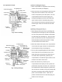
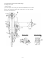
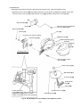
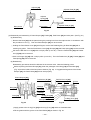
(1) Disassembly and reassembly of Nose [22], Pushing Lever (A) [31] and other parts
(a) Disassembly (See Figs. 21 and 22.)
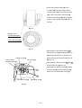
Remove the four Nylock High Tension Bolts M6 x 20 [23]. Then the Nose [22], Pushing Lever (A) [31] and
other parts can be removed.
(b) Reassembly
Disassembly procedures should be followed in the reverse order. Note the following points.
Apply grease to the O-ring (S-46) [13] and mount it in the groove of the Nose [22].
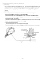
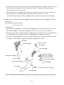
Align the bent portion of Adjuster Plate (A) [47] with the concave portion of the Pushing Lever Guide [40].
After reassembly, check the components of the pushing lever and the Adjuster [44] move smoothly.
Pushing Lever Guide [40]
Adjuster [44]
Bent portion of Adjuster
Plate (A) [47]
Align the positions.
Fig. 22
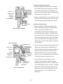
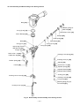
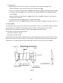
(2) Disassembly and reassembly of the adjuster unit
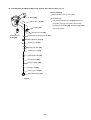
(a) Disassembly (See Fig. 23.)
Remove the Retaining Ring (E-type) for D3 Shaft [51]. Then Pushing Lever (A) [31], Pushing Lever Cover
(B) [30] and the adjuster unit can be removed.
Pull out the Roll Pin D2 x 16 [43]. Then the adjuster unit can be disassembled.
(b) Disassembly
Disassembly procedures should be followed in the reverse order. Note the following points.
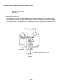
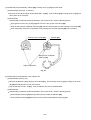
Mount Adjuster Plate (A) [47] facing its bent portion toward the Adjuster [44].
Mount Adjuster Plate (B) [46] facing its convex portion toward Adjsuter Plate (A) [47].
--- 32 ---