1
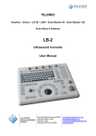
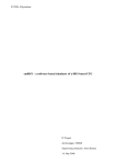
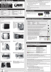
PHASETRONICS
SCR Power Control Specialists
EP1 Series Power Control
Single Phase SCR
10 - 50 Amps
OPERATION & SERVICE MANUAL
Phasetronics, Inc.
P.O. Box 5988
1600 Sunshine Drive
Clearwater, FL 33765
(727)573-1900 FAX(727)573-1803
EP1 Series
SCR Power Control
Description
The EP1 Series of Phase Angle SCR Power Controls assures smooth
proportional output power from 0 to 100%. This high quality SCR control is
offered in single or a three phase version with a variety of options. These
options include current limit, soft start current trip, voltage regulation and I2t
fusing. The unit is ideally suited for all resistive and inductive or variable
loads. The soft start feature assures a slow rising output voltage to prevent
an inrush on inductive or variable resistance loads. The control input is
adjustable to match all standard temperature and process controllers. The
control signal sensitivity is adjustable by gain and offset potentiometers.
The unit can be controlled from an external manual potentiometer. MOVs
(standard) protect the SCRs from transient voltages. False firing (dv/dt)
protection is standard.
Receiving
Upon receipt of this product you should immediately do the following:
√ Inspect the unit for possible shipping damage. If damaged, notify
the freight carrier and file a claim within 15 days of receipt.
√ Verify the model number on the unit matches you purchase
order.
√ Verify that the unit is the correct current and voltage for your
application.
Warning!
Do Not Service Equipment with voltage applied! Unit
can be a source of fatal electrical shocks. To avoid
shock hazard, disconnect main power before working
on unit.
-1-
EP1 Series
SCR Power Control
Specifications
Inputs
Milliamp Input
4-20 mA Input Impedance - 250 ohms
Analog Input
0-10 Vdc Signal / 0-5 Vdc Signal - 100k ohms input impedance
Manual Control
10k ohm, 2 watt potentiometer, linear taper
Output Current Rating
10 to 1000 Amps
Output Stage
Back to Back configuration
AC Supply Voltage
120/208/240/308/415/480/575 Vac(+10% to -15%, 50/60 Hz)
Type of Loads
Resistive / Inductive / Lamp
Soft Start
Hard Firing Gate Pulse
Input
Adjustments
Gain
4-20mA, 0-5 Vdc, 0-10 Volts
Offset
50% of gain maximum
Regulation
(Option R)
Protective
Networks
Factory set for initial half-second of operation of power on. Field
adjustable via potentiometer from 0.2 seconds to 30 seconds
A combination of a high-potential gate pulse and a rapid rise time is
used to prevent SCR damage due t di/dt stress
Optional feature to provide load avrage voltage regulation of plus
or minus 2% for +10% to -10% of gain maximum
Optional Fusing
Transient Voltage
Suppressor
SCR Peak Inverse
Voltage (PIV Rating)
I2t fuse protects against short-circuit overloads (Option F)
RC Snubber
RC snubber networks prevent false firing due to dv/dt
characteristics
Ambient Temperature
Integral MOV (Metal Oxide Varistor) protects against high
potential transient voltage
2.5 times line rating (minimum)
Operating range is from 0 C thru 40 C (30 F thru 122 F)
Protective Networks
Transient Voltage Suppressor (standard) - Integral MOV (Metal Oxide
Varistor) protects against high potential voltage spikes.
RC Snubber (Standard) - RC Snubber networks are used to prevent false
firing due to dv/dt characteristics.
SCR Peak Inverse Voltage (PIV Rating)
Line Voltage:
120 - 480
575
Continuous SCR Rating
1200 Volts
1500 Volts
Ambient Temperature
Ambient temperature operating range is 0 to 40 degrees C (32 to 122 F).
Output rating decreases by 10% for each 5 degree C rise (9° F) in ambient
temperature over 40 degrees C (122° F) to a max of 60 degrees C (140° F).
Transportation and storage range is -30 to 65 degrees C (-30 to 149° F).
-2-
EP1 Series
SCR Power Control
Location
Proper location of the EP1 Series is necessary to achieve specified
performance and normal operation. The EP1 Series should always be
installed in an area where the following conditions exist:
•
•
•
•
•
•
Ambient operating temperature is 0 to 40 degrees C (32 to 104° F)
Protected from rain and moisture
Humidity range from 5% to 95% non-condensing
Free from metallic particles, conductive dust and corrosive gas
Free from excessive vibration (below 0.5G)
Open panel units must be mounted in the appropriate type of
enclosure. Enclosure size and type must be suitable to dissipate
heat generated by the SCR power control. (NEMA 1 style
enclosures can be vented to reduce size)
Formulas for sizing
Non-vented painted
metal enclosures
Units maximum current (FLA) x 1.5 = watts then
watts / 10 = sq.ft. of exposed area
Non-vented stainless
steel enclosures
( FLA10x 1.5 )
Warning!
x 1.5 = sq.ft. of exposed area
Do not service equipment with voltage applied! Unit can
be source of fatal electrical shocks! To avoid shock
hazard, remove all sources of power before working on
controller. Warning labels must be attached to terminals,
enclosure and control panel to meet local codes.
Mounting and Cleaning
If mounting the EP1 Series unit in an enclosure requires drilling or punching
holes in the enclosure, cover the electrical assembly to protect unit from
metal filings that could short out electronics. After work is complete,
thoroughly clean the area and reinspect the EP1 Series. Make sure there is
sufficient clearance (six inches) all around the EP1 Series unit for cooling.
The unit must be installed with its heat sink ribs oriented vertically and running
parallel to the mounting surface.
Unit should be cleaned on a regular basis to insure proper cooling. Do not
use any chemicals to clean the unit, use 80 to 100 psi clean dry compressed
air only. A three inch high quality dry paint brush is helpful to loosen up the
dust prior to using compressed air on the unit.
-3-
EP1 Series
SCR Power Control
Manual Control Connections
If manual potentiometer is not used, proceed to
Automatic Control Connections. Manual
potentiometer does not have to be connected for
unit to operate.
Connect manual potentiometer to TB2-3(wiper),
TB2-4(high) and TB2-6(low) per connection ( See
Figure 1 for connections & Figure 2 for locations).
Figure 1 - Manual Connections
Automatic Control Connections
Connect DC voltage or milliamp input signal to pins 1(positive) and
2(negative) on TB2. You must select the proper jumper for 4-20 mA*, 0-5
Vdc or 0-10 Vdc. (See location of jumpers and pins Figure 2)
0-10 Vdc connection
jumper X4 installed
mA connection
* 4-20
jumper X2 installed (factory setting)
0-5 Vdc connection
jumper X3 installed
Figure 2 - TB2 Connections
If manual and automatic control are both used, consider using an external
auto/manual switch to stop the manual setting from overriding the automatic
signal.
-4-
EP1 Series
SCR Power Control
Power Connections
Make line 1 connection to L1 and Load connection to T1. (See Figure 3)
If option card is not used connect L2 (using 18-22 gauge wire) to terminal
6 on TB1(EPCL1000). (See Figure 3)
If option card is used, connect L2 to terminal 7 of TB2 on option card.
(See Figure 4)
L2 connection (if no
option card is present)
L1 (Hot)
T1 (To Load)
Figure 3 - Power Connection (no option card)
Option Card
(mounted on main logic board when options are ordered)
L2 Connected to TB2-7
on option card
Figure 4 - Power Connection (with option card)
Soft Start (Standard)
Soft start ramp adjustment is factory set (P3) for 0.5 seconds. The soft start
ramp time can be increased to a maximum of 30 seconds by adjusting P3 in
a clockwise(CW) direction. Note: Soft start is active only when initial power
is applied and a command signal is present. It has no effect on control
signal change. (See Option S on page 6 if soft start is required on restart of
mA signal or when lockout is released.)
-5-
EP1 Series
SCR Power Control
Options
The following options are available on the EP1 Series but must be specified
when ordering. When options are ordered a separate option card is mounted
on top of the main logic board.
Soft Start (Option “S”)
Provides soft start on a signal change or when lockout is released. This will
help protect fuses. The unit is set up so that either of these two soft start
modes can be disabled by removing X1 & X2 on option card (See figure 5
below or Option board page 8). The unit will ramp up on a signal change if
this signal is set below a threshold level. The threshold is adjustable from 0
to 30 seconds of control signal range.
Current Limit (Option “C”)
Provides flexibility for changing loads, helps protect unit. Adjustable from
10-110% of unit rating. Current limit will override control input signal to limit
the output current. Current transformer included. To disable remove X1 &
X3 on option card. (See figure 5 below or Option board page 8)
Current Trip (Option “T”)
Used as a protective measure. This option will shut down unit when the
current exceeds an adjusted preset level. Adjustable from 75-200% for
instantaneous trip if current exceeds set level. Unit can be connected for
manual reset. Current transformer included. To disable remove X4. (See
figure 5 below or Option board page 8)
Line Voltage Regulation (Option “R”)
Provides more accurate linearity. Will maintain output within 2% with a +/10% line variation.
Option Card (mounted on main logic board)
Note: The number of
potentiometers on the option
card will vary depending on
the options ordered.
Figure 5 - Option setting locations
-6-
EP1 Series
SCR Power Control
Main Logic Board (EP1 Series - 10 - 50 Amp)
L2 Connection (used when
no option card is present)
-7-
EP1 Series
SCR Power Control
EP1 Series Option Board
This board is mounted on main logicboard when options are ordered.
L2 Connection
-8-
Warranty Policy
Motortronics warrants its products to be free from defects in material and/or
workmanship for a period of one year from date of installation, to a maximum
of 18 months from the date of shipment as indicated by the unit’s date code.
The Company reserves the right to repair or replace any malfunctioning
units under warranty at their option. All warranty repairs must be performed
by the Company factory, or on site by a factory authorized service firms or
personnel approved by the Company.
Solid state controls have different operation characteristics from those of
electro-mechanical equipment. Because of these differences and the wide
variety of applications for solid state controls, each application designer
must verify that the solid state equipment is acceptable for his application.
In no event will Motortronics be responsible or liable for indirect or
consequential damages resulting from the use or application of this
equipment. The diagrams and illustrations in this document are included
solely for illustrative purposes. Because of the number of different
applications, Motortronics can not be responsible or liable for actual use
based on the examples or diagrams.
-9-