1
Group 2
Service Procedures
Assembly
2
1
T2007112
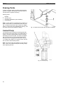
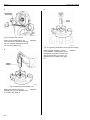
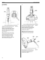
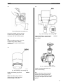
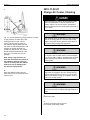
Fig. 85: Installing bearing and shaft into pump
T2007111
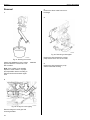
Fig. 84: Installing bearing to shaft sleeve
Install the new bearing (3) to the shaft
sleeve (2) and, using hollow drift
9998012, carefully press down on the
inner race of the bearing until it lies up
against the flange of the shaft sleeve;
see Fig. 83: Exploded view of coolant
pump, page 51.
Note: Install the bearing with the side
at which the outer and inner races are
level facing the flange of the shaft
sleeve. The shaft (1) and the shaft
sleeve (2) are supplied as a single
spare part unit; see Fig. 83: Exploded
view of coolant pump, page 51.
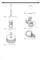
9998012
Place the pump housing (5) in a press.
Using hollow drift 9996383, carefully
press in the bearing and shaft until the
bearing bottoms out in the pump housing; see Fig. 83: Exploded view of
coolant pump, page 51.
9996383
Note: Press on the outer race of the
bearing and check to make sure that
the shaft does not hit the press table.
3
T2007119
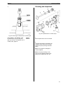
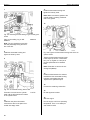
Fig. 86: Press drive gear onto shaft
Screw the shorter threaded section of
spindle 9996315 into the shaft sleeve
(2); see Fig. 83: Exploded view of
coolant pump, page 51.
52
9996315