1
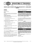
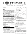
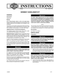
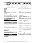
-J06260
REV. 2015-05-21
FRONT TURN SIGNAL RELOCATION KIT
GENERAL
Kit Number
When servicing the fuel system, do not smoke or allow
open flame or sparks in the vicinity. Gasoline is extremely
flammable and highly explosive, which could result in
death or serious injury. (00330a)
67800557
Models
For model fitment information, see the P&A retail catalog or
the Parts and Accessories section of www.harley-davidson.com
(English only).
Installation Requirements
The rider's safety depends upon the correct installation
of this kit. Use the appropriate service manual procedures.
If the procedure is not within your capabilities or you do
not have the correct tools, have a Harley-Davidson dealer
perform the installation. Improper installation of this kit
could result in death or serious injury. (00333a)
REMOVAL
1.
Remove seat. Retain all seat mounting hardware.
NOTE
When moving fuel tank back, do not damage fuel gauge wires
clipped to frame under left side of tank.
2.
Remove the front and rear fuel tank mounting hardware
per the service manual. Move the fuel tank back on the
frame to gain access to the wire harness caddy.
3.
See Figure 1. Remove TORX screw (3). Separate left
caddy section (2) from right section (4) and vehicle frame
(1).
NOTE
is08609
This instruction sheet refers to service manual information. A
service manual for this year/model motorcycle is required for
this installation. One is available from a Harley-Davidson dealer.
1
3
Kit Contents
2
See Figure 3 and Table 1.
PREPARATION
To prevent spray of fuel, purge system of high-pressure
fuel before supply line is disconnected. Gasoline is
extremely flammable and highly explosive, which could
result in death or serious injury. (00275a)
4
Purge and disconnect fuel supply line.
1.
2.
3.
4.
To prevent accidental vehicle start-up, which could cause
death or serious injury, remove main fuse before proceeding. (00251b)
NOTE
•
•
WITH security siren: With security fob present, turn
ignition switch ON. See the service manual. Disarm
security system. Turn ignition switch OFF. IMMEDIATELY
remove the main fuse.
WITHOUT security siren: See the service manual.
Remove main fuse.
-J06260
Vehicle frame
Left wire harness caddy section
TORX screw
Right wire harness caddy section
Figure 1. Access Main Harness
NOTE
Electrical connectors are identified in the service manual by
the numbers and letters shown here within brackets.
4.
5.
Pull wire harness away from inside the caddy enough to
disconnect the black 6-way Multilock turn signal connector
[31]. Set aside frame-side connector half [31A].
See the service manual. Remove the socket terminals
from the lamp-side connector half [31B]. Record the wire
1 of 4
Many Harley-Davidson® Parts & Accessories are made of plastics and metals which can be recycled.
Please dispose of materials responsibly.
colors installed in the cavities of the connector, which
should be:
•
Black [BK] right turn signal wire in cavity 1
•
Brown [BN] right turn signal wire in cavity 2
•
Blue [BE] right turn signal wire in cavity 3
•
Blue [BE] left turn signal wire in cavity 4
•
Violet [V] left turn signal wire in cavity 5
•
Black [BK] left turn signal wire in cavity 6
6.
Remove the grommet from the end of the turn signal wire
vinyl conduit still connected to the switch housing.
7.
Make about a 1.0 in (25 mm) long slit in the end of the
conduit.
is04978b
8
6
5
1.
2.
3.
4.
5.
6.
7.
8.
See Figure 3. Slip the 2.0 in (51 mm) long section of
encapsulating (dual wall) shrink tube (8) over the conduit
and wires, next to the turn signal housing.
•
Avoid directing heat toward any fuel system component.
Extreme heat can cause fuel ignition/explosion resulting
in death or serious injury.
•
Avoid directing heat toward any electrical system component other than the tubing on which heat shrink work is
being performed.
•
Always keep hands away from tool tip area and heat shrink
attachment.
9.
Use a heat gun or suitable radiant-heating device to shrink
the tubing to the wires and conduit.
4
1
Cut back the second wire about 0.2 in (6 mm) from the
end of the conduit.
Be sure to follow manufacturer's instructions when using
the UltraTorch UT-100 or any other radiant heating device.
Failure to follow manufacturer's instructions can cause a
fire, which could result in death or serious injury. (00335a)
2
7
Cut back one wire about 0.5 in (12 mm) from the end of
the conduit.
8.
3
Left side turn signal
Right side turn signal
Wire slot (2)
Cap screw (2)
Lockwasher (2)
Triple clamp
Pinch bolt (2)
Six-way connector
Figure 2. Installation of Mounting Bracket and Wire
Harness (View From Underside)
2.
Install the screw (4) and lockwasher (5) into the stalk and
through the hole. Position the turn signal lamp against the
end of the stalk. Thread the screw into the lamp housing,
but do not fully tighten.
3.
Place the mounting bracket in position on the lower fork
above the triple clamp (6). Align the lamp to face forward
and parallel to the ground. While holding the alignment,
remove the assembly. Tighten the lamp mounting screw
(4) to 70-80 in-lbs (8-9 Nm).
4.
Install the mounting bracket assembly to the lower fork
with a pinch bolt (7), making sure that:
a.
The lamp is facing forward and parallel to the ground.
b.
The exiting wire centers in the wire notch (3) at the
stalk base.
c.
The stalk does not pinch the wire against the fork
bracket.
10. Assemble the switches and switch housings to the
handlebar per service manual instructions, tucking the
shrink-sealed wire ends back inside the switch housings.
5.
Tighten the pinch bolt (7) to 70-80 in-lbs (8-9 Nm).
11. Repeat on the opposite side of the vehicle.
6.
Repeat steps 1-5 for the opposite side.
INSTALLATION
NOTE
Make sure that wires do not pull tight when handlebars are
turned fully to left or right fork stops.
NOTES
See Figure 2. The harness exiting the turn signal lamp has a
flat cross-section, similar to the slot (3) near the lamp end of
the stalk.
7.
See Figure 2. Install the socket terminals from the turn
signal harnesses into the lamp-side black 6-way Multilock
connector half [31B] per the service manual. Unless noted
differently on removal,
For best appearance:
•
Align the harness along its full length. Determine the flat
side that lies against the stalk with the lamp attached.
•
Black [BK] right turn signal wire in cavity 1
•
Brown [BN] right turn signal wire in cavity 2
•
Insert the harness into the slot in that orientation to avoid
a half-twist in the wire harness at the lamp.
•
Blue [BE] right turn signal wire in cavity 3
1.
See Figure 2. Carefully feed the length of wire from the
turn signal lamp into the stalk through the wire slot (3).
•
Blue [BE] left turn signal wire in cavity 4
•
Violet [V] left turn signal wire in cavity 5
•
Black [BK] left turn signal wire in cavity 6
-J06260
2 of 4
8.
See Figure 1. Feed the assembled connector [31B], from
the outside, into the wire caddy (4) in the right side of the
frame behind the steering head.
9.
Plug the connector half into the mating connector half
coming from the frame.
10. Temporarily install the main fuse per the service manual.
entangled or pinched. Secure any excess harness length
with a cable strap. Stow inside the steering head.
14. Push the wire harness up inside the frame, behind the
steering head. Position the harness shield (1) to the
underside of the top bar with the tabs (2) inside. Push
upward until the tabs engage the holes (3) on each side
of the frame.
11. Test the turn signals to verify that they function correctly.
To prevent accidental vehicle start-up, which could cause
death or serious injury, remove main fuse before proceeding. (00251b)
12. Remove main fuse.
When servicing the fuel system, do not smoke or allow
open flame or sparks in the vicinity. Gasoline is extremely
flammable and highly explosive, which could result in
death or serious injury. (00330a)
15. Install fuel tank. Connect the fuel line per the service
manual.
16. Install main fuse.
Be sure that steering is smooth and free without interference. Interference with steering could result in loss of
vehicle control and death or serious injury. (00371a)
•
Make sure wires do not pull tight when handlebars
are turned fully to left or right fork stops.
13. Use cable straps as necessary to secure the harnesses
so they do not interfere with steering function, or become
-J06260
After installing seat, pull upward on seat to be sure it is
locked in position. While riding, a loose seat can shift
causing loss of control, which could result in death or
serious injury. (00070b)
17. See the service manual. Install seat.
3 of 4
SERVICE PARTS
is07098c
8
2
1
5
4
7
3
6
Figure 3. Service Parts: Front Turn Signal Relocation Kit
Table 1. Service Parts
Item
Description (Quantity)
Part Number
1
Bracket assembly, front turn signal relocation (right, black)
Not sold separately
2
Bracket assembly, front turn signal relocation (left, black)
Not sold separately
3
Socket head cap screw, 5-16-18 x 1/2 in (13 mm) long, with lock patch (2)
3340
4
Lock washer, split, 5/16 in (2)
7042
5
Screw, hex socket button head, 1/4-20 x 5/8 in (16 mm) long (2)
926
6
Recess cover, turn signal, black (2)
68749-09
7
Cable strap (8)
10065
8
Shrink tube (6)
67113-83
-J06260
4 of 4