1
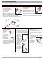
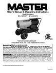
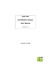
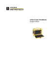
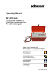
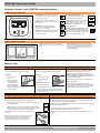
150R/150T Quick Start Guide
Getting to Know Your 150R/T/B Locating System
150R Controls Overview
On-Off/Cancel: To turn on, press. To turn
off, press again. To cancel current action
in menu mode, press.
Signal Strength Display: Signal
strength is shown by bars at top of
display and in numeric display.
Up Arrow: To increase manual gain,
press. To scroll up menu options in menu
mode, press.
Gain Display: Gain (amount of signal
amplification) is shown by bars below
signal strength indicator. Gain
increases to the right and in numeric
display at lower left.
Menu/Select: To access the menu
screen, press. To select highlighted
menu option, press again.
Down Arrow: To decrease manual gain,
press. To scroll down menu options in
menu mode, press.
Receiver Battery Level Display: Three
segments mean that batteries are at full
level. One segment means that batteries
are at low level. No segments means that
you should change batteries soon.
150T Controls Overview
Power: Position switch up for high power
output, down for low power output and center
for off.
Green LED: Indicates sufficient battery level
when solid. Light begins to flash when battery
becomes low. If light flashes when unit is turned
on, then batteries are low or one battery is
installed backwards.
Startup Tips
Installing the Batteries
Choosing Signal Type
150R
150T
Use two C-cell alkaline batteries in receiver.
Use six C-cell alkaline batteries in transmitter.
To install
To install
1. Remove battery
cover.
1. Open battery cover.
2. Insert batteries as
shown with positive
(+) ends pointing
toward the display
end of the receiver.
3. Install and tighten battery cover.
4. Check operation.
2. Insert batteries as
shown.
Active: There are three ways to place active
signals on a target line with a transmitter. Direct
connection (preferred method) requires a
connection to be made directly onto target line.
Induction clamp requires placing a clamp around
target line. Broadcast induction sends signal into
all lines near the transmitter.
Beacon: Beacon signals allow metallic and non
metallic pipe tracing.
IMPORTANT: Do not mix
new and used batteries.
3. Close and tighten battery cover.
Passive: Power utility lines can be located
passively without a transmitter. Use 60P to locate
utilities from main line to transformer and use 60S
to locate utilities from transformer to meter.
4. Check operation. If green LED flashes upon
startup, then battery installation is incorrect or
batteries are weak.
Antenna Configuration
Frequency
The receiver is factory configured in one of two antenna configurations: peak
or null. However, peak units and null units have the ability to operate in either
mode by rotating the receiver 90° in either direction.
The 150R is factory configured in either peak or null mode. Units configured to
operate in Peak mode will have one active frequency (640hz, 30kHz or 83kHz) as
well as two passive power modes (60S and 60P). Units configured to operate in
Null mode will have only one frequency (83kHz).
•
•
Peak: Response is highest at strongest signal. When to use:
in most applications.
Null: Response is lowest when receiver is over the line or
beacon. When to use: to verify location of target line after it
has been located in peak antenna configuration.
All 150R receiver units can locate in either peak or
null mode.
The 150T transmitter is designed to place signals on target lines and is configured
in either 30kHz or 83kHz frequency.
•
Lower frequencies travel farther than higher frequencies.
•
Higher frequencies couple onto lines more easily.
•
Higher frequencies also couple onto lines other than the target line more
easily.
Rotate receiver 90° to locate using other antenna
mode. When rotated 90°, a peak configured
receiver will function as a null receiver or a null
configured receiver will function as a peak.
IMPORTANT: See Operator’s Manual for detailed safety and operating instructions.
Laminated: P/N 790-1009 B
150R/150T Quick Start Guide
Operating Your 150R and 150T Locating System
Active Location - Direct Connect
Active Location - Induction Clamp
NOTICE: Turn off transmitter when connecting or moving ground stake.
1. Plug cable into transmitter (1).
2. Place clamp around line (2).
1. Drive ground stake (4).
3. Turn on transmitter.
2. Plug cable into transmitter (2).
4. Check battery level.
3. Hook black lead to ground stake (3).
NOTICE: Do not unplug induction clamp from
transmitter when connected to line. Removing
cable will cause an arc and could damage
equipment or cause injury.
4. Hook red lead to line (1).
5. Turn on transmitter.
6. Check battery level indicator.
NOTICE: Do not unplug direct connect cable
when connected to line. Removing cable will
cause an arc and could damage equipment or cause injury.
7. Walk in an arc approximately 25’ (7.5 m) around transmitter.
5. Walk in an arc approximately 25’ (7.5 m) around transmitter.
6. Hold the receiver so that the handle points toward the transmitter, as
shown.
7. Identify location of line by finding the spot with the best signal response.
8. Hold the receiver so that the handle points toward the transmitter, as
shown.
9. Identify location of line by finding the spot with the best signal response.
Active Location - Broadcast
Passive Location
Beacon Location
1. Remove cable, stake, clamp and any other
metal objects from transmitter.
1. Turn on receiver.
1. Install beacon battery with positive end away
from battery cap.
2. Place transmitter
parallel to and
directly above
suspected line as
shown.
Note: Transmitter
must be parallel to
object, as shown, in
order to produce the
best signal.
3. Turn on transmitter.
4. Check battery level
indicator.
5. Walk in an arc
approximately 25’ (7.5 m) around transmitter.
6. Hold the receiver so that points toward the
transmitter, as shown.
7. Identify location of line by finding the spot with
the best signal response.
2. Select frequency and antenna configuration.
3. Make a visual check of the site for signs of
buried lines such as: recent trenching, buried
line markers, overhead lines that run down pole
and underground, gas meters, valve sights, and
drains or manhole covers.
4. Search the site by
walking a grid
pattern while
holding receiver
close to the ground.
Keep the receiver
horizontal.
5. Move the receiver
over the detected
signal to find the
best signal response. If using a peak antenna
mode, rotate the receiver until the signal is
strongest. Strongest signal indicates line
direction.
6. Walk along the
suspected path
while moving the
receiver side to
side.
2. Turn on receiver to ensure that beacon is
functioning properly.
3. Attach beacon to plumber’s snake or flex rod.
4. Place beacon into pipe and move it down the
pipe.
5. To locate beacon, circle over its approximate
location in the pipe.
6. To identify beacon location find the spot with the
strongest signal response.
7. Rotate the receiver
to determine which
direction the
beacon runs.
IMPORTANT:
Receiver indicates
the strongest signal
when handle is
perpendicular to
the beacon.
8. Continue to track the beacon. Mark pipe
location with paint.
7. Sweep, focus, and
trace all detected
signals in the area.
Mark line paths with
colored paint or
flags.
IMPORTANT: See Operator’s Manual for detailed safety and operating instructions.
Laminated: P/N 790-1009 B