1
∼ Installation Procedures ∼
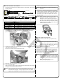
3.Disconnect the genuine injector wire harness(2P coupler).
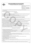
●Before installation
This product must be installed with the stock PGM-FI system which operates
properly.
If the PGM-FI system is in bad condition, this controller will not operate correctly
CO
or provide the performance, as a result it causes damage of this product or
other related parts.
To install and use this controller, make sure that your stock PGM-FI system
operates properly. Before you start working, stand your vehicle securely on
a flat surface such as a maintenance stand placed on a jack.
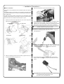
1.Remove the center cover, Right side cover, front cover and leg shield
・(referring to the genuine service manual).
Center cover
4.Check the wire color of the disconnected genuine harness(2P coupler).
If the sub wire harness 1COMP. in the kit and the wire colors are
opposite in color, do the following procedure to counterchange the places
of the genuine coupler wires.(Color of wires has to be matched.)
R. side cover
Front cover
Leg shield
Caution: If the wires are opposite in color, you cannot turn on the FI controller, therefore, the engine will not start.
◆ Procedures to counterchange the wires of 2P coupler
a.Remove the retainer(grey plastic part) from the stock coupler with a small slotted driver.
PY
b.Pull out the wires individually from the coupler with a pick while pulling up
the inner hook fixing the terminal of the stock coupler. At this time, you do
not have to remove the retainer on wire side and rubber seal.
2.Attach the supplied ground wire with the battery negative terminal, and
the wire will be routed to the ignition coil.
c.Insert the wires to the coupler to match the colors of the sub wire harness 1 COMP. included in the kit and push the retainer back into the coupler.
Caution:Make sure that the terminal should be pushed in with facing up,
or the terminal will not insert into the coupler. Be careful not to insert upside down.
-3-
Sep./30/’
11