1
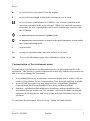
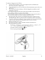
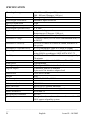
Biochrom Ltd
Certificate No. 890333
Declaration of Conformity
This is to certify that the
Ultrospec 1100 pro UV/Vis Spectrophotometer
Part number 80-2112-00 / 01 / 02 / 03
Serial number 79000 onwards
and the
Ultrospec 500 pro Visible only Spectrophotometer
Part number 80-2112-50 / 51 / 52 / 53
Serial number 79000 onwards
manufactured by Biochrom Ltd. conform to the requirements of the following
Directives-:
73/23/EEC & 89/336/EEC
Standards to which conformity is declared
• EN 61 010-1: 1993 Safety requirements for electrical equipment for measurement,
control and laboratory use.
• EN 61326-2.3: 1998 Electromagnetic compatibility - Generic emission standard
part 1. Electrical equipment for measurement, control and laboratory use.
• EN 61000-4-6: 1992 Electromagnetic compatibility - Generic immunity standard
part 1. Residential, commercial and light industry.
Dated: 2nd April 2002
Signed:
David Parr
Managing Director
Biochrom Ltd
Postal address
Telephone
Telefax
Biochrom Ltd
22 Cambridge Science Park
Milton Road
Cambridge CB4 0FJ
England
+44 1223 423723
+44 1223 420164
e mail: [email protected]
website: http://www.biochrom.co.uk
Registered in England No: 974213
Registered Office: 22 Cambridge Science Park, Milton Road, Cambridge CB4 0FJ, England.
CONTENTS
Unpacking, Positioning and Installation
Essential Safety Notes
OPERATION
Introduction
Using the Instrument Display and Keypad
Customisation of the instrument menu
Basic Modes of Use
Enhanced Modes of Use
Method storage, recall and deletion
SET-UP
Menu customisation, access code and methods
Lamp settings
Display contrast and instrument output
1
2
3
3
4
5
6
10
18
19
19
20
20
ERROR MESSAGES
21
OUTPUT OF RESULTS
22
Use with parallel printer
Use with chart recorder
Use with PC
22
22
22
ACCESSORIES
Lamps, consumables and other items
MAINTENANCE
After Sales Support
Lamp Replacement
Deuterium Lamp Warranty (Ultrospec 1100 pro)
Fuse replacement
Cleaning and general care of the instrument
APPENDIX
Equation entry using the Multi Wavelength mode
SPECIFICATION
Warranty
23
23
24
24
24
26
26
26
27
27
28
30
Unpacking, Positioning and Installation
•
Inspect the instrument for any signs of damage caused in transit. If any damage
is discovered, inform your supplier immediately. Check the position of the metal
lamp bracket inside the lamp access area.
•
Ensure your proposed installation site conforms to the environmental conditions
for safe operation:
Indoor use only
Temperature 10°C to 40°C
Maximum relative humidity of 80 % up to 31°C decreasing linearly to 50 % at
40°C
•
The instrument must be placed on a hard, flat bench or table that can take its
weight (6 kg) such that air is allowed to circulate freely around the instrument.
•
Ensure that the cooling fan inlets and outlets are not obstructed; position at
least 2 inches from the wall.
•
This equipment must be connected to the power supply with the power cord
supplied and MUST BE EARTHED (GROUNDED). It can be used on 90 - 240V
supplies.
•
Switch on the instrument. Prior to calibration, the display asks you to check that
the cell compartment is clear. The purpose of this is to indicate the use of the
function soft keys, and how they are associated with the options presented at
the bottom of the display; F2 represents OK in this instance (this display can be
disabled in Set-up if required). The calibration stages are indicated in sequence
(- for checking, ü for OK, û for Fail).
•
At switch on the language of the instrument can be changed if required. The
relevant key should be held down while the instrument is switched on. The
following numbers correspond to the languages available:
0 English
1 German
2 French
3 Spanish
4 Italian
If this equipment is used in a manner not specified or in environmental conditions not
appropriate for safe operation, the protection provided by the equipment may be
impaired and instrument warranty withdrawn.
________________________________________________________________
___
Issue 02 - 08/2002
English
1
Essential Safety Notes
There are a number of warning labels and symbols on your instrument. These are
there to inform you where potential danger exists or particular caution is required.
Before commencing installation, please take time to familiarise yourself with these
symbols and their meaning.
Caution (refer to accompanying documents).
Background colour yellow, symbol and outline black.
WARNING
UV RADIATION
HOT
WARNING
UV RADIATION IS HARMFUL TO YOUR EYES
If power is restored with this cover removed,
eye protection must be worn
________________________________________________________________
___
2
English
Issue 02 – 08/2002
OPERATION
Introduction
Your spectrophotometer is a simple-to-use, microprocessor-controlled instrument. In
addition to the basic modes of operation, the instrument has enhanced software and
method storage functionality. A laboratory technician or supervisor can customise
the spectrophotometer for students and operators by disabling menu options that are
not required.
Your spectrophotometer:
•
has basic modes of operation ♦
♦
•
measurement of absorbance, % transmission and concentration values,
output of simple kinetics assays and wavelength scans to display.
has enhanced modes of operation ♦
♦
♦
♦
the facility to enter a multi point standard curve in memory
the application of a factor to an absorbance change over a specified time
interval for an enzymatic determination (reaction rate)
the use of absorbance values in a multi wavelength equation specified by
you, with direct output of results, saving post run calculation
the ability to quantify nucleic acids using stored equations and factors
(Ultrospec 1100 pro only)
•
stores up to 9 user defined methods
•
can have any combination of the above, including methods, enabled so as to
customise the instrument for your own specific laboratory needs
•
can be connected to a standard Centronics parallel printer for output of results
•
can be linked via a serial interface adapter lead to a PC for download of results to
spreadsheet, and subsequent inclusion in a laboratory information management
system (LIMS)
A range of accessories further enhances the capability of the instrument.
________________________________________________________________
___
Issue 02 - 08/2002
English
3
Using the Instrument Display and Keypad
The back-lit liquid crystal display has large characters which are easily visible, useful
if a group of students are gathered around for a demonstration, for example. The
keypad is a spill proof membrane that is very hard wearing.
The instrument is easy to use, with function select / entry soft keys on the keypad
(F1, F2 and F3) being situated directly below the corresponding option on the
display; these keys are used in conjunction with on-screen prompts.
On the absorbance home page, for example, concise help text is available at the push
of the F1 key, whereas Menu and Set-up are accessed by F2 and F3, respectively. On
other displays, the purpose of the keys changes, but this is clearly indicated; for
example, F3 acts as the “accept” option on parameter entry displays and next page (if
further options exist) in the Menu and Set-up displays.
Pressing the red stop key acts as an escape mechanism in most situations.
________________________________________________________________
___
4
English
Issue 02 – 08/2002
Press:
←
to clear incorrect user entries from the display.
λ
to enter the wavelength at which the instrument is to be used.
to set reference of absorbance to 0.000AU on a reference solution at the
current wavelength in the mode selected. Where it is standard operating
procedure, the user is prompted to insert a cell containing a reference into
the cell holder.
to start making measurements or print results.
to stop making measurements or return to the initial parameter screen within
the current operating mode.
•
to print result
Esc
to stop an experiment (time intervals and wavescan only)
OK
To go to the absorbance page after calibration or from set-up.
Customisation of the instrument menu
Customisation of the menu to suit laboratory needs is an important benefit of the
instrument. This facility is password protected so that only authorised personnel are
able to set up or change the instrument.
•
•
•
In a teaching laboratory, a laboratory technician might choose to have only the
modes of Absorbance, Factor Concentration, Time Intervals and Scan available.
In the QC lab, the supervisor may choose to have Absorbance, Standard
Concentration, Multi-point Standard Curve entry and Reaction Rate.
Similarly, a production line might have Absorbance and two methods as the
instrument start up; in this case, the methods could both be multi wavelength
equations involving factors, and set up in the analytical laboratory for use by
operators.
To customise the instrument, refer to Set-up > Menu for further details.
________________________________________________________________
___
Issue 02 - 08/2002
English
5
Basic Modes of Use
Absorbance
Absorbance mode is default after power on and calibration. It makes simple
absorbance measurements on samples, measuring the amount of light that has
passed through a sample relative to a blank (this can be air). The procedure is as
follows:
Press λ key and enter appropriate wavelength
Insert reference, press
key.
This reference value is used for subsequent samples until changed.
Insert samples as required and record the absorbance.
% Transmission
Transmission mode measures the amount of light that has passed through a sample
relative to a blank (this can be air), but displays the result as a percentage. The
procedure is as follows:
Press λ key and enter appropriate wavelength
Insert reference, press
key
This reference value is used for subsequent samples until changed.
Insert samples as required and record the transmittance.
Concentration
Factor concentration mode is used when a conversion factor is known, and is
required to convert the absorbance measurement for a sample at a specific
wavelength into a concentration, by a simple multiplication of absorbance x factor.
The procedure is as follows:
Enter appropriate wavelength
Enter known factor (range 0.01-99999)
Insert reference, press
key
This reference value is used for subsequent samples until changed.
If you wish to save as a method, go to set-up (F3)
________________________________________________________________
___
6
English
Issue 02 – 08/2002
Insert samples as required and record the concentrations.
________________________________________________________________
___
Issue 02 - 08/2002
English
7
Time Intervals
Simple kinetics studies for teaching laboratory experiments can be readily performed.
The wavelength of interest is entered together with the time interval at which
absorbances are to be read; the option of having a reference reading prior to the run
is available. A count down facility indicates the time remaining until the next
measurement. To end an experiment, the stop key is pressed. The procedure is as
follows:
Enter appropriate wavelength
Enter time unit (seconds or minutes)
Enter end time ( 10,000)
Enter the time interval for each reading (range 1-60 seconds). A minimum of 10 data
points are required, and the time interval for this is calculated.
If you require a reference reading press F3 (if not, press F2)
Insert reference, press
key
This reference value is used for subsequent samples until changed.
If you wish to save as a method, go to set-up (F3)
Insert sample, press
key
Press . to print graphic
Press
key when the experiment is complete
________________________________________________________________
___
8
English
Issue 02 – 08/2002
Wavescan
An absorption spectrum can be obtained from your instrument; this enables simple
identification of peak height and position. A reference scan has to be obtained first
since there is no stored baseline. The procedure is as follows:
Enter start wavelength
Enter end wavelength (nearest 10, 20, 50 or 100 nm to start wavelength)
Insert reference, press
key
This reference value is used for subsequent samples until changed.
If you wish to save as a method, go to set-up (F3)
Insert sample, press
key (repeat as necessary)
Press . to print graphic
Use the 3 (F1) and 4 (F3) keys to move the cursor in order to identify peak height
and position.
To zoom in on a region, press F2 followed by the start and end wavelengths (the
instrument will zoom to the nearest 10, 20, 50 or 100 nm).
________________________________________________________________
___
Issue 02 - 08/2002
English
9
Enhanced Modes of Use
Standard Concentration
Standard Concentration mode is used when a sample of known concentration is
available; by measuring the absorbance of this at a specific wavelength, the
conversion factor is calculated (see above), and this can be applied to other samples
of unknown concentration. This is equivalent to a one point calibration, and
assumes that a sample of zero concentration has zero absorbance. The procedure is
as follows:
Enter appropriate wavelength
Enter concentration of known standard
Insert reference, press
key
This reference value is used for subsequent samples until changed.
Insert standard, press
The absorbance value is displayed; press F2.
If you wish to save as a method, go to set-up (F3)
Insert samples as required and record the concentrations relative to the standard.
If recalling as a method, set reference before measuring samples.
________________________________________________________________
___
10
English
Issue 02 – 08/2002
Standard Curve
The construction of a multi point calibration curve from standards of known
concentration in order to quantify unknown samples is a fundamental use of a
spectrophotometer; this instrument has the advantage of being able to store this
curve as a method. The procedure to construct the standard curve is as follows:
Select whether cubic spline or linear regression fit of the data points is required
Enter appropriate wavelength
Input the number of standards to be used:
For cubic spline fit, a minimum of 4 standards is required; maximum is 10.
For linear regression, a minimum of 3 data points is required (if 1 is entered,
the mode reverts to standard concentration); maximum is 10.
Enter the concentrations of the standards in increasing value *.
Insert reference, press
key
This reference value is used for subsequent samples until changed.
Insert standard 1 of known concentration, press
The absorbance is displayed; press F2 to proceed to next standard.
Repeat as necessary for all standards
Press . to print graphic
The display shows - - - -, signifying that the standard curve has been defined, and
that samples can now be measured.
If you wish to save as a method, go to set-up (F3)
Insert samples as required and record the concentrations relative to the standard
curve.
Any sample absorbance / concentration which is outside the limits defined by the
standards used is displayed as - - - - .
If recalling as a method, set reference before measuring samples. The display
continues to show - - - - after the set reference. To recall stored method parameters
only, for example in protein assays where freshly prepared standards are frequently
used with new samples, press STOP after method recall. Press enter to move through
the stored method parameters, and measure the absorbances of the fresh standards
in the usual way; these new values are used in the standard curve.
-
To include a zero concentration standard, include this in the number of
standards to be entered and enter 0.00 for concentration; use a blank when
________________________________________________________________
___
Issue 02 - 08/2002
English
11
required to enter standard 1. If using duplicates, enter the same concentration
twice; 2 duplicates of 3 different concentration equals 6 standards.
________________________________________________________________
___
12
English
Issue 02 – 08/2002
Reaction Rate
Reagent test kits are routinely used for the enzymatic determination of compounds in
food, beverage and clinical laboratories by measuring NAD / NADH conversion at
340 nm. The change in absorbance over a specified time period can be used to
provide useful information when an appropriate factor, defined in the reagent kit
protocol, is applied.
Note that reaction rate and enzyme activity can be calculated if the factor used takes
account of the absorbance difference per unit time, as opposed to the absorbance
difference per se.
The correlation (quality of line fit) is calculated from 10 equally spaced absorbance /
time points during the course of the experiment. The procedure is as follows:
Enter appropriate wavelength
Enter time unit (seconds or minutes)
Enter delay time, if applicable (0 600)
Enter end time ( 10,000)
Enter factor (range 0.01-99999)
If you require a reference reading press F3 (if not, press F2)
Insert reference, press
key
This reference value is used for subsequent samples until changed.
If you wish to save as a method, go to set-up (F3)
Insert sample, press
key.
The display indicates the change in absorbance for each of the calculated time
intervals as the assay proceeds.
The result (total change in absorbance over the reaction time multiplied by the factor)
is displayed; press F2 to display the correlation (a correlation of > 0.95 is expected if
the assay was carried out over a linear section).
If recalling as a method, set reference before measuring samples.
________________________________________________________________
___
Issue 02 - 08/2002
English
13
Multi Wavelength Equation Entry
The measurement of Absorbance values at specific wavelengths and combining
these with appropriate factors is a means of overcoming interference effects in
several applications. By using the equation entry facility, post measurement
calculations can be done automatically and the end result displayed for the operator.
This is a very powerful facility indeed for the busy industrial, QC or environmental
testing laboratory. Up to 5 wavelengths and 6 constants (5 factors relating to the
absorbances at the 5 wavelengths, and a dilution factor) can be entered for one
equation. The procedure is as follows (refer to Appendix for a step by step, worked
through example):
Write the equation out in front of you, ensuring there are no syntax errors!
The available equation operators are:
A@1 Absorbance at wavelength 1. Enter required wavelength using keypad.
(
)
+
*
/
K1
Factor applied to absorbance at wavelength 1. Enter using keypad.
C1
Constant (dilution or other). Enter using keypad. Note that C1 can be
applied several times, using different numerical values each occasion.
!
Use if a sequence of Absorbance values only is required Enter !A@1 A@2
etc
Note that Factor and Constant can only have 5 characters, including the decimal
point; thus 12.259 is not allowed, whereas 0.302 is.
The maximum length of equation that can be accommodated is 60 characters in
length, where the absorbance at wavelength and factor are 3 and 5 characters,
respectively, and the equation operators are 1 character.
Press Next (F1) to obtain the required parameter, using the keypad for absorbance
values and factors, as appropriate.
Press F2 to select the parameter and move on to the next one.
Repeat this procedure until the equation is entered.
Note that if you make an error, the ← key on the keypad will remove the last entry.
Press F3 to enter the equation once it has been input correctly.
Insert reference, press
key. A set reference at each of the required wavelengths
is taken.
If you wish to save as a method, go to set-up (F3)
Insert sample, press
key.
The result of the calculations involved in the defined equation is displayed.
________________________________________________________________
___
14
English
Issue 02 – 08/2002
Press F2 to proceed to next sample
If recalling as a method, set reference before measuring samples.
________________________________________________________________
___
Issue 02 - 08/2002
English
15
Nucleic Acid Quantification (Ultrospec 1100 pro)
Nucleic acids can be quantified at 260 nm because it is well established that a
solution of DNA or RNA with an optical density of 1.0 has a concentration of 50 or
40 µg/ml, respectively, in a 10mm pathlength cell. Oligonucleotides, as a rule of
thumb, have a corresponding factor of 33 µg/ml, although this does vary with base
composition.
Extracting nucleic acids from cells is accompanied by protein, and extensive
purification is required to separate the protein impurity. The 260/280 ratio gives an
indication of purity; it is only this, however, and not a definitive assessment. Pure
DNA and RNA preparations have expected ratios of ≥ 1.8 and ≥ 2.0, respectively;
deviations from this indicate the presence of protein impurity in the sample, but care
must be taken in interpretation of results. An elevated absorbance at 230 nm can
indicate the presence of impurities as well; 230 nm is near the absorbance maximum of
peptide bonds and also indicates buffer contamination since Tris, EDTA and other
buffer salts absorb at this wavelength. When measuring RNA samples, the 260/230
ratio should be > 2.0; a ratio lower than this is generally indicative of contamination
with guanidinium thiocyanate, a reagent commonly used in RNA purification and
which absorbs over the 230 – 260 nm range.
Background correction at a wavelength totally separate from the nucleic acid and
protein peaks at 260 and 280 nm, respectively, is sometimes used to compensate for
the effects of background absorbance. The wavelength used is 320 nm and it can
allow for the effects of turbidity, high absorbance buffer solution and the use of
reduced aperture cells.
The instrument calculates concentration, displays 260/280 and 260/230 ratios, and
compensates for dilution and use of cells that do not have 10mm pathlength (2mm).
We do not recommend the use of cells containing less than 70µl of solution in this
instrument (the microvolume cell, 80-2103-69, is ideal for Nucleic Acid Quantification).
The procedure is as follows:
Enter Nucleic Acid type (DNA, RNA, Oligo)
[If Oligo, enter appropriate conversion factor if known (default is 33)]
Enter if background correction at 320nm is required
Enter units (µg/ml, ng/µl or µg/µl)
Enter dilution factor (range 1.0 – 99999)
Enter pathlength of cell used (10, 5 or 2mm)
Insert reference, press
key. A set reference at each of the required wavelengths
is taken.
If you wish to save as a method, go to set-up (F3)
Insert sample, press
key.
________________________________________________________________
___
16
English
Issue 02 – 08/2002
The results for absorbance values, concentration and the purity ratios are displayed.
Press F2 to proceed to next sample
If recalling as a method, set reference before measuring samples.
________________________________________________________________
___
Issue 02 - 08/2002
English
17
Method storage, recall and deletion
After defining parameters in any of the above modes, and prior to measuring a
sample, entry to Set-up using the F3 function key provides the opportunity to store
the parameters currently loaded as a method. This option is password protected, and
up to 9 methods can be saved; refer to Set-up > Methods for further details.
A stored method is enabled as an option directly on the instrument menu, so that it is
possible for an operator to switch the instrument on and have a specified method
available straight away; refer to Set-up > Menu for further details.
When recalling a stored method from the menu, the option to print the method
parameters is presented by pressing 1; press 2 to continue with the selected method.
Print the method to confirm that it is the method you require, if necessary. Once a
method has been recalled, you can set reference before running samples.
If method parameters are incorrect, they cannot be changed – the method has to be
erased (deleted), re-entered and then re-stored (re-saved). To remove a method, refer
to Set-up > Methods.
________________________________________________________________
___
18
English
Issue 02 – 08/2002
SET-UP
After selecting the set-up option (F3) there is an initial information screen, as shown
below. Press F2 (OK) to return to the absorbance home page. Press F1 to recalibrate
the instrument.
Serial #
4110 or 4140 V2.0
UV lamp hours
Vis lamp hours
Instrument hours
Serial Number of the instrument
Product line number, version of EPROM
Total UV lamp life used (Ultrospec 1100 pro)
Total visible lamp life used
Total instrument hours
To access the set-up page press F3 again. A password is required; the default is
4110 or 4140, but this can be changed.
Three displays are available:
Menu customisation, access code and methods
Lamp settings
Display contrast and instrument output
To go to the next display press F3.
To change or select an option press the relevant number on the keypad. Another
display screen may appear depending on the option.
Use the function soft keys in conjunction with the options indicated by the display,
as appropriate.
Menu customisation, access code and methods
1 : Menu
2 : All Menu
3 . Access Code
Press 1 to obtain a list of all the modes. These can be enabled
or disabled as required by pressing the relevant number on the
keypad. Disabled options are not shown on the main menu
display.
Press 2 to show disabled options from above as greyed out text
on the main menu, even though they cannot be selected.
Press 3 for the possibility to change the password from the
default to another 4 digit number. Enter the current password
(Access Code), then the new one (Access Code #1) and confirm
the new one (Access Code #2). If you forget the password,
contact your supplier.
________________________________________________________________
___
Issue 02 - 08/2002
English
19
4 : Methods
Press 4 to have the choice of either storing a new method
after defining parameters or erasing an existing method.
Press 1 to store the method in the next available method
storage space (maximum is 9). Methods are stored in the
instrument EEPROM, the process may take a few seconds.
Press 2 to erase a method; the method number has to be
entered.
Method parameters can be printed out when the stored
method is selected from the menu.
Lamp settings
1 : UV lamp
2 : Vis lamp only
3 : UV lamp save
4 : Lamp hours ⇒ 0
Switch deuterium lamp on/off (Ultrospec 1100 pro)
Deuterium lamp is switched permanently off; and the
instrument will act as a visible only product. Infrequent
users of the UV range can benefit from considerable
increase in deuterium lamp life by use of this utility.
Instrument powers up and calibrates as usual, but then
switches off the deuterium lamp automatically. The lamp will
come on if a UV wavelength is selected (Ultrospec 1100 pro)
Resets lamp lives to zero when a new lamp is fitted.
Display contrast and instrument output
1 : ⇑ Contrast
2 : ⇓ Contrast
3 : Calibration Menu
4 : Output to serial
5 : Output to printer
Increase display contrast one step at a time by pressing 1
Decrease display contrast one step at a time by pressing 2
(a total of seven contrast levels are available)
Disables the “Ensure cell compartment is clear” message
which appears prior to calibration.
Enables output of ASCII datastream to PC via the serial
interface adapter lead. The information is in tab separated
format.
Enables output to parallel printer via a standard Centronics
cable; text only, Seiko DPU-414, HP DeskJet (A4), HP
DeskJet (letter).
________________________________________________________________
___
20
English
Issue 02 – 08/2002
ERROR MESSAGES
The following are a selection of error messages that are available:
Reset to defaults
UV lamp fail
Vis lamp fail
Beam blocked
Wavelength error
Lamps overheating
PSU overheating
Memory was corrupted in some way and re-set to defaults.
Display options and methods need to be re-entered.
UV lamp failed to strike. May need replacing – check lamp
hours (Ultrospec 1100 pro)
Visible lamp failed to strike. May need replacing – check
lamp hours
Something is in the way of the beam – check sample
compartment area
A calibration failure or corruption has caused the instrument
to go an invalid wavelength. May need service engineer.
The thermal sensor on the lamp cover has detected a
temperature in excess of its limits – call service engineer.
PSU thermistor is indicating a temperature in excess of 70°C
– call service engineer.
________________________________________________________________
___
Issue 02 - 08/2002
English
21
OUTPUT OF RESULTS
Use with parallel printer
Any Centronics parallel printer can be used together with the appropriate cable. If
using a thermal printer, ensure it is set up to print out for a page width of 80
characters. Ensure output to printer is on in the Set-up.
Output is automatic when the
key is pressed, and a printer is connected and
switched on. Umlauts and accents are not printed out with letters if the instrument is
set up to be in German, French, Italian or Spanish.
Appropriate headers and relevant information are printed out for enhanced modes,
for example the absorbance – concentration values of the standards in standard
curve mode, and the equation (with values) entered in Multi Wavelength mode.
Use with chart recorder
The chart recorder interface lead, 80-2109-03, is required; time intervals and scan
modes only will output to a chart recorder in a meaningful way. The output is via pin
24 (+) and pin 25 (-) of the 25 pin D connector if you wish to make your own.
Output is non-synchronised, that is the chart recorder must be switched to run
independently. The output is 100 mV for 1.000 abs unit, and a suggested chart speed
is 10 mm / second. Note that an offset is required; - 0.5 Abs = 0 mV, 0.0 Abs = 50 mV,
3.0 Abs = 350 mV (use Absorbance mode to set these pen positions on the chart
recorder).
Use with PC
NOTE: A standard serial interface will not work.
1) Download to Spreadsheet
The serial interface adapter lead (80-2109-02) is required; it is also supplied with
Spreadsheet Interface Software for direct download to Excel. This macro is supplied
on a floppy disc together with instructions for installation and use.
2) Use with Hyperterminal
The serial interface adapter lead (80-2109-02) is required; ensure output to serial is on
in Set-up. The ASCII stream is output at 19,200 Baud via the 25 way D connector on
the rear panel, and can be picked up by a PC with Windows installed. Use the
Hyperterminal emulator in Accessories to pick this up (settings are Handshake None,
19,200 Baud, 1 stop bit, 8 data bits, 0 parity, Comm port depends on which port the
lead is connected to). Output is automatic if the interface lead is connected to the
instrument.
________________________________________________________________
___
22
English
Issue 02 – 08/2002
ACCESSORIES
Each accessory is supplied integrated into its own sample compartment for ease of
fitting and cleaning.
Easy to fit when changing accessory / sample compartment, snap the old one
out and the new one in.
Easy to clean - take the whole assembly out and run it under the tap.
SWIFT 1000 applications software
Manual 2 position 10mm cell changer
10 – 50mm cell holder
Water heated cell holder
(requires circulating bath)
Electrically heated cell holder
(requires Temperature Controller)
Temperature Controller (25, 30, 37°C)
Fitting kit for external sample delivery
(requires peristaltic pump and 10mm pathlength flowcell)
Test tube holder and cover
(accommodates diameters of 8-26 mm and heights of up to 180 mm)
Spare 10mm single cell holder
80-2110-00
80-2109-04
80-2109-05
80-2109-06
80-2109-07
80-2109-01
80-2109-08
80-2109-33
80-2109-09
Lamps, consumables and other items
Tungsten halogen lamp
Deuterium lamp (Ultrospec 1100 pro)
Service Manual
Serial Interface Adapter Lead
(includes Spreadsheet Interface Software)
Chart Recorder Lead
Centronics parallel printer lead
Dust cover
80-2106-16
80-2109-11
80-2108-67
80-2109-02
80-2109-03
80-2071-87
80-2109-13
Contact your supplier for details on our range of disposable, UV silica and glass
cells.
________________________________________________________________
___
Issue 02 - 08/2002
English
23
MAINTENANCE
After Sales Support
We supply support agreements that help you to fulfil the demands of regulatory
guidelines concerning GLP/GMP.
♦
♦
♦
Calibration, certification using filters traceable to international standards
Certificated engineers and calibrated test equipment
Approved to ISO 9001 standard
Choice of agreement apart from break down coverage can include
♦
♦
Preventative maintenance
Certification
When using calibration standard filters, insert such that the flat surface is facing
away from the spring end of the cell holder
Observe all necessary precautions if dealing with hazardous samples or solvents.
Lamp Replacement
Replacement lamps are available from your supplier using the following part numbers:
Deuterium Lamp
80-2109-11 (Ultrospec 1100 pro)
Tungsten Lamp
80-2106-16
(use only this tungsten lamp; others will not operate correctly in a
spectrophotometer)
The design of the lamp area is such that users are able to change their own lamps.
No lamp alignment is necessary as the lamps are pre-aligned at manufacture.
The lamps become very hot in use. Ensure they cool before changing them.
Do not touch the optical surfaces of either lamp with your fingers (use tissue); if
touched, the area should be cleaned with iso-propanol.
________________________________________________________________
___
24
English
Issue 02 – 08/2002
To replace a lamp proceed as follows:
1)
Switch off the instrument, remove the sample from the cell holder and
disconnect the power supply cord.
2)
Locate the lamp access cover at the back of the instrument, unscrew the cover
and remove.
3)
Move the metal bracket sideways, slide the lamp plate assembly out and
unplug the connector.
if the tungsten lamp has failed, the replacement should be inserted onto the
plate, pushing it all the way down into its holder.
if the deuterium lamp has failed, insert the old tungsten lamp onto the plate as
above and then replace the whole assembly with the new one.
4)
Reconnect the cable connector and slide the lamp plate in until it locates,
checking that the cable or connector does not interfere with the relocation.
5)
If you have difficulty in sliding the lamp assembly back into position hold the
connector down and push the lamp plate until it locates correctly.
6)
Replace the lamp access cover.
7)
Reconnect the power supply cord and switch the instrument on.
8)
Reset the lamp life to zero by:
F3 Set-up → F3 Set-up → enter password → F3, F3 → select 4 → F3
(ü), → select which lamp life is to be changed to zero.
Exit this screen by pressing the
key
Exit set-up by pressing the
key.
________________________________________________________________
___
Issue 02 - 08/2002
English
25
Deuterium Lamp Warranty (Ultrospec 1100 pro)
Criteria for lamp replacement are that it must:
-
be less than 15 months old AND
have had less than 750 hours use
Fuse replacement
Switch off the instrument and disconnect the power supply cord. The fuse holder
can only be opened if the power supply plug has been removed, and is located
between the power input socket and the on/off switch on the back panel of the
instrument.
Slide open the fuse holder by pulling at the notch.
Place fuses (2A, 5mm x 20mm, FST) into the fuse holder and slide back into position.
Reconnect the power supply cord and switch on the instrument.
Fuses are not normally consumed in an instrument’s lifetime. If they blow repeatedly,
contact your supplier.
Cleaning and general care of the instrument
External cleaning
Switch off the instrument and disconnect the power cord.
Use a soft damp cloth.
Clean all external surfaces.
A mild liquid detergent may be used to remove stubborn marks.
Sample compartment spillage
Switch off the instrument and disconnect the power cord.
Remove the cell holder by snapping it out.
Clean it separately with a soft damp cloth, or hold it under running water from a tap.
________________________________________________________________
___
26
English
Issue 02 – 08/2002
APPENDIX
Equation entry using the Multi Wavelength mode
Always write out the equation in front of you before using this mode.
Step by step entry of the following equation is shown in the example below:
Cobalt (g/l) = ( (A511 * 12.26) – (A720 * 0.302) ) * 100
Note that if you make an error, the ← key on the keypad will remove the last entry.
Press Next (F1) until ( appears. Press select (F2).
Press Next (F1) until ( appears. Press select (F2).
Press Next (F1) until A@1 appears. Press select (F2).
Press 511 on the keypad. Press enter (F3).
Press Next (F1) until * appears. Press select (F2).
Press Next (F1) until K1 appears. Press select (F2).
Press 12.26 on the keypad. Press enter (F3).
Press Next (F1) until ) appears. Press select (F2).
Press Next (F1) until – appears. Press select (F2).
Press Next (F1) until ( appears. Press select (F2).
Press Next (F1) until A@2 appears. Press select (F2).
Press 720 on the keypad. Press enter (F3).
Press Next (F1) until * appears. Press select (F2).
Press Next (F1) until K2 appears. Press select (F2).
Press 0.302 on the keypad. Press enter (F3).
Press Next (F1) until ) appears. Press select (F2).
Press Next (F1) until ) appears. Press select (F2).
Press Next (F1) until * appears. Press select (F2).
Press Next (F1) until C1 appears. Press select (F2).
Press 100 on the keypad. Press enter (F3).
Check the equation on the display.
Press F3 to accept the equation
To save the equation as a method, refer to Set-up.
________________________________________________________________
___
Issue 02 - 08/2002
English
27
SPECIFICATION
Wavelength range
Monochromator
Wavelength calibration
Spectral bandwidth
Wavelength accuracy
Wavelength reproducibility
Light sources
Detector
Photometric range
Photometric linearity
Photometric reproducibility
Stray Light
Stability
Noise
Scan speed
Analogue output
Digital output
Dimensions
Weight
Power requirements
Safety standard
EMC emissions
EMC immunity
Mains harmonics
Susceptibility standard
Quality System
325- 900 nm (Ultrospec 500 pro) or
200 – 900 nm (Ultrospec 1100 pro)
Plane grating with 1200 lines/mm
automatic upon switch on
5 nm
± 2nm
± 0.5nm
tungsten halogen and
deuterium arc (Ultrospec 1100 pro)
single solid state silicon photodiode
- 0.300 to 3.000A, 0.01 to 99999 concentration units, 0.1
to 200%T
±0.5% or ± 0.005A to 2.000A at 546nm, whichever is
the greater
0.5% of absorbance value to 2.000A at 546nm
typically <0.2%T at 220nm using NaI, <0.2%T at 340nm
using NaNO2 according to ANSI/ASTM E387-72
± 0.002A/h at 0A and 546nm after warm-up, typically
30 minutes
± 0.001A near 0A and ± 0.002A near 2A at 600nm
250 nm/minute
100mV per 1.000A via interface lead
Centronics parallel as standard
9 pin serial via interface adapter lead
370 x 430 x 130 mm
6 kg
90-265 V, 50/60 Hz, 100 VA
EN61010-1
EN 61326-2.3 Generic emissions
EN 61000-4-6 Generic immunity part 1
EN 61000-3-2
IEC 801
Designed and manufactured in accordance with an ISO
9001 approved quality system
________________________________________________________________
___
28
English
Issue 02 – 08/2002
Specifications are measured after the instrument has warmed up at a constant
ambient temperature and are typical of a production unit. As part of our policy of
continuous development, we reserve the right to alter specifications without notice.
________________________________________________________________
___
Issue 02 - 08/2002
English
29
Warranty
Your supplier guarantees that the product supplied has been thoroughly tested to
ensure that it meets its published specification. The warranty included in the
conditions of supply is valid for 12 months only if the product has been used
according to the instructions supplied. They can accept no liability for loss or
damage, however caused, arising from the faulty or incorrect use of this product.
This product has been designed and manufactured by Biochrom Ltd, 22 Cambridge
Science Park, Milton Road, Cambridge CB4 0FJ, UK.
________________________________________________________________
___
30
English
Issue 02 – 08/2002