1
2
2. SPECIFICATIONS
2.1. PERFORMANCE
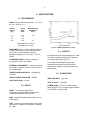
NOISE Based on silicon equivalent of = 3.6 eV at
2 = 2 µs. (See Fig. 2.1.)
Detector
Capacity
(pF)
0
20
50
100
Typical
Noise
(keV)
Maximum Noise
Guaranteed
(KeV)
1.55
1.73
2.23
3.25
1.75
3.6
Typical intercept, 1.55 keV.
Typical slope, 17 eV/pF.
RISE TIME Based on a +0.5-V signal through the
E output into a 93 circuit and measured from
10% to 90% of peak amplitude; rise time
adjustment optimized; 5 ns at 0 pF, 12 ns at
100 pF.
CONVERSION GAIN Nominal, measured
through the E output, 45 mV/MeV.
INTEGRAL NONLINEARITY Measured through
the E output, 0.05% for 0 to ±7 V open circuit, or
±3.5 V terminated.
TEMPERATURE INSTABILITY <±50 ppm/(C,
0 to 50(C.
DETECTOR BIAS ISOLATION
±5000V.
OPEN LOOP GAIN 40,000.
2.2. INPUTS
INPUT Accepts input signals from
semiconductor charged-particle detector and
extends operating bias to the detector.
BIAS Accepts the detector bias voltage from a
power supply.
TEST Accepts input voltage pulses from a pulse
generator for instrument and system calibration;
Rin = 93.
Fig. 2.1. 142AH Typical Noise (0.5 )s).
2.3. OUTPUTS
E Furnishes the output signals through Ro = 93 for energy measurements; polarity is opposite
from input pulse polarity (Fig. 2.4.).
T Furnishes a differentiated output signal
compatible with typical 50 timing system
requirements; polarity is the same as the input
pulse polarity.
2.4. CONNECTORS
INPUT AND BIAS
Type SHV.
TEST, E, AND T Type BNC.
POWER CABLE 10-ft (3-m) captive power
cable (ORTEC 121-C1); longer lengths available
from ORTEC on special order.