1
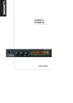
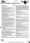
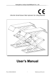
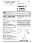
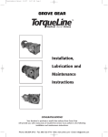
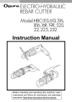
200-PUMP: 99900120: 20070329 Model 200 AIR/HYDRAULIC PUMP PARTS AND SERVICE MANUAL IOWA MOLD TOOLING CO., INC. BOX 189, GARNER, IA 50438-0189 TEL: 641-923-3711 TECHNICAL SUPPORT FAX: 641-923-2424 MANUAL PART NUMBER 99900120 Iowa Mold Tooling Co., Inc. is an Oshkosh Truck Corporation company. 200-PUMP: 99900120: 19920508 TABLE OF CONTENTS PARAGRAPH TITLE PAGE SECTION 1. DESCRIPTION 1-1. 1-2. DESCRIPTION ............................................................................................................. 1-1 OPERATION ................................................................................................................. 1-1 SECTION 2. SERVICE 2-1. 2-2. 2-2-1. 2-2-2. 2-3. 2-4. 2-5. GENERAL .................................................................................................................... AIR/HYDRAULIC PUMP ............................................................................................... PUMP DISASSEMBLY ................................................................................................. PUMP ASSEMBLY ....................................................................................................... CLEANING ................................................................................................................... STORAGE .................................................................................................................... TROUBLESHOOTING .................................................................................................. 2-1 2-1 2-1 2-2 2-3 2-3 2-3 SECTION 3. PARTS 3-1. 3-2. GENERAL .................................................................................................................... 3-1 ORDERING REPAIR PARTS ........................................................................................ 3-1 SECTION 4. LUBRICATION 4-1. 4-2. 4-3. 4-4. OIL SELECTION .......................................................................................................... OIL SPECIFICATIONS ................................................................................................. CONTAMINATION AND TESTING ................................................................................ LUBRICATION .............................................................................................................. 4-1 4-1 4-1 4-1 LIST OF ILLUSTRATIONS FIGURE TITLE B-1. C-1. C-2. C-2A. D-1. TROUBLESHOOTING CHART ..................................................................................... PUMP ASSEMBLY W/HOSE .................................................. 51705747 ..................... AIR/HYDRAULIC PUMP - PARTS ........................................... 73051460 ..................... AIR/HYDRAULIC PUMP - DRAWING ...................................... 73051460 ..................... HYDRAULIC OIL SPECIFICATIONS ............................................................................. PART NUMBER PAGE 2-3 3-1 3-2 3-3 4-1 200-PUMP: 99900120: 19920508 1-1 SECTION 1. DESCRIPTION 1-1. DESCRIPTION 1-2. OPERATION The IMT 200 Air/Hydraulic Pump supplies hydraulic fluid pressure to selected tools such as the 210 HP Bead Breaker. It consists of an in-line air and hydraulic cylinder. The ratio of hydraulic fluid pressure generated compared to supply air pressure is 100:1. In other words, 100 PSI out for every 1 PSI in - 100 PSI input air pressure equals 10,000 PSI output pressure. Operation of the unit is as follows: Depressing the RELEASE pedal causes a decrease in pressure and pressing the PUMP end of the pedal provides fluid pressure. WARNING The air/hydraulic pump is capable of generating fluid pressure up to 10,000 PSI. Make certain the tool in use is held securely and is in proper working condition. Do not continue to operate the pump once the work is completed. Failure to comply with these instructions could result in personal injury or damage to the equipment. Connect the hose of the Air/Hydraulic Pump to the hydraulic coupling on the selected tool. Connect the air supply line to the Air/Hydraulic Pump. Air supply should be 5-10 CFM at 100 PSI to obtain proper operating characteristics. In addition, the air line should be equipped with an air line filter. Stepping on the PUMP end of the pedal engages the pump, producing the force necessary to run the tool. Depressing the RELEASE end of the pump pedal will release the pressure. 200-PUMP: 99900120: 19920508 2-1 SECTION 2. SERVICE 2-1. GENERAL 2-2-1. PUMP DISASSEMBLY Most malfunctions are a direct result of foreign matter - dirt, dust, water, etc. - entering the pump. Keep all unions clean and capped when the pump is not connected to a tool. If the Air/Hydraulic Pump is to be used only with one tool, it is recommended that the pump be permanently attached to that tool. This is accomplished by removing any quick-disconnects from the tool, inserting a swivel and attaching the hose from the pump directly to the swivel. Use a pipe thread compound when assembling. This will eliminate the possibility of contamination through open couplings. To disassemble, proceed as follows (refer to Figure C-2 for parts information): The pump is relatively easy to service. Some tools will be required for disassembly. These are: 1. Vise 2. Common screwdriver 3. Needle-nosed pliers 4. Ice pick or sharp awl 5. Allen wrenches 6. Open end wrenches 7. Retaining ring pliers 8. Socket wrenches 9. Ratchet 10. Torque wrench Remove the twelve self-tapping screws (69) and lift off the cover/pump assembly. Set the reservoir (57) and gasket (55) to one side. Remove the six socket head screws (61 & 84) and lift off the muffler (42 & 72), the intake air valve body (68), the release valve body (66) and cover (63). The air valve may be disassembled by removing the socket head screw (36), drawing item 39 and 40 out of the top and items 36 and 38 out of the bottom. The release valve may be further disassembled by drawing items 1, 44, 45 and 47 out of the bottom. The pump assembly (under the cover) may also be disassembled. Lift out the springs (5, 34 & 46) and ball (6). Clamp the rear head (27) in a vise. Remove the four socket head screws (70). 2-2. AIR/HYDRAULIC PUMP Before disassembling the pump, the outside must be thoroughly washed to prevent contaminating the interior. Before washing, remove the pedal (67) by removing one of the E retaining rings and sliding the pin (64) out of the hole. Wash thoroughly with warm, soapy water, rinse with clean water and wipe or blow the pump dry. CAUTION Do not use solvents. Solvents may be corrosive to seals. Proceed with disassembly in a clean, warm environment - one that is free of dust, dirt, etc. and has a temperature of 70°F or warmer. NOTE It is easier to remove three socket head screws (70) completely and then, using hand pressure to hold the pump body in place, remove the fourth screw. Spring tension (20) will cause the pump body to lift away from the cylinder (60). Carefully lift off the pump body (8), the hydraulic piston, spring guide and spring (13, 20 & 21). Lift the cylinder (60) off the rear head. Push the air piston out of the cylinder. Remove the three socket head screws and washers (28 & 29) from the air piston assembly. Remove all parts. The piston poppet (31) can be pulled off the end of the exhaust valve stem (32). Remove the piston rings and back-up rings (25 & 33) with a small, common screwdriver. 200-PUMP: 99900120: 19920508 Place the pump body (8) in a vise with the cylinder end facing up. Remove the retaining nut (17). The u-cup will have to be pressed out from the other end of the pump body. Remove the cylinder (15) with a 1" socket. Reposition the pump body in the vise so that the filter (12) is on top. Remove the filter, adapter, copper washer and ball (9, 10, 11 & 12). Insert a common screwdriver in the slot at the top of the poppet retainer (48). Rotate it back-and-forth to loosen it. Grip the retainer and pull it out of the pump body. NOTE Socket head screw and washer (3 & 4) are used as a plug. There is no need to remove them. Relief valve (7) is factory preset at 10,000 PSI. There should be no need for its removal. If it is defective, replace the entire relief valve assembly. The new assembly is also preset. Do not disassemble before installation or the setting will be incorrect. Disassembly is complete. 2-2-2. PUMP ASSEMBLY The pump is assembled as follows: NOTE Use all components supplied with the seal kit. Insert the release valve components (48, 49, 50, 51, 52, 53 & 54) into the pump body (8). Position the pump body in a vise with the filter port up. Install the filter, adapter, copper washer and ball (9, 10, 11, 12 & 58). Reposition the pump body with the cylinder end up. Install the cylinder, u-cup, retainer nut, and copper gasket (14, 15, 16 & 17). Clamp the rear head (27) in a vise and insert the back-up ring (59). Assemble the piston (22, 23, 24, 25, 26, 28, 29, 30, 31, 32 & 33). Apply Loctite® to the threads of the socket head screws (29) and torque them to 50 - 55 in-lbs. Lubricate the piston rings and the inside of the air cylinder with oil. Insert the piston into the air cylinder and squirt more oil around the circumference of the piston. Work the piston back-and-forth to distribute the oil. 2-2 Position the cylinder/piston group on the rear head with the groove on the inside of the cylinder toward the top of the rear head. Position the back-up ring (59) on the pump body. Position the spring guide, hydraulic piston and spring (13, 20 & 21) over the air piston. Align the pump body so the hydraulic piston slides through the retainer nut (17). Push the pump body down against the cylinder. Install the four socket head screws and washers and torque them to 85 - 90 in-lbs. NOTE The easiest way to assemble the rear head, cylinder and pump body is to start one screw and get it finger tight. That will take up the spring tension and make it easier to install the others. Position the pump assembly in the vise with the top up. Place new gaskets on the pump body and rear head. Oil will help hold them in position. Place the cover on top of the gaskets and insert the o-rings (35 & 2). With your fingers, press item 1, 44, 45 and 47 into the ports in the release valve body. Place the ball (6) and springs (5 & 46) into the ports of the pump body. Install item 58 (must be pressed into place). Align the release valve body on the cover and start the four socket head screws. Do not tighten the screws. Install items 36, 37, 38 and 40 in the air valve body. Place the spring (34) in the port in the rear head. Position the muffler (42 & 72) between the valve bodies and secure the valve bodies in place (torque the screws to 25 - 30 in-lbs.). Position the pedal and slide the pin through the valve body and pedal. Secure it with the other E retaining ring. Position the assembled pump in the reservoir. Fill the reservoir with oil and prime the pump. 200-PUMP: 99900120: 19920508 To prime the pump, connect the air supply line to the air inlet. Depress the PUMP end of the pedal and hold down the release valve with a common screwdriver. Allow the pump to cycle 15 - 20 times. Remove the screwdriver and depress the PUMP end of the pedal. If pressure builds, the pump has primed; if not, repeat this step until it does build pressure. 2-3 2-4. STORAGE Anytime the pump is stored, it is wise to wash any spilled chloride or other harmful chemicals from its exterior. Use warm, soapy water and be certain to rinse with clear water and dry thoroughly. Doing so on a regular schedule will increase the life of the equipment. 2-5. TROUBLESHOOTING 2-3. CLEANING Wash the exterior of the pump with warm, soapy water. Rinse with clean water and dry using compresed air. Pay particular attention to the release valve area of the pump. This may become encrusted with dirt to the extent that the release mechanism will no longer function. Figure B-1 lists problems, probable causes and solutions for the pump. refer to the parts drawings. CAUTION Do not use solvent. Solvents may be corrosive to the seals and damage them. FIGURE B-1. TROUBLESHOOTING CHART 200-PUMP: 99900120: 20000706 3-1 SECTION 3. PARTS 3-1. GENERAL 3-2. ORDERING REPAIR PARTS This section contains the parts drawings and parts lists for the IMT 200HP Air/Hydraulic Pump. To order parts: 1. Give the model number. 2. Give the serial number located on the side of the pump. 3. Give the part number, description and quantity required. Place your order with Iowa Mold Tooling Co., Inc., Box 189, Garner, IA 50438, telephone 641-923-3711, Fax 641-923-2424; or your nearest distributor. ITEM 1. 2. 3. 4. 5. PART NO. 51073049 72532047 72532281 73051460 99900120 DESCRIPTION QTY HOSE ASM 84" 1 DISCONNECT NIPPLE 1/4MPT-AIR DISCONNECT COUPLER 1/4FPT PUMP - AIR/HYD 5-QT (SEE DWG) MANUAL-200 AIR/HYD PUMP FIGURE C-1. PUMP ASSEMBLY W/HOSE (51705747) 1 1 1 1 200-PUMP: 99900120: 19920508 3-2 ITEM PART NO. DESCRIPTION QTY COMMENTS 1. 2. 3. 4. 5. 6. 7. 8. 9. 10. 11. 12. 13. 14. 15. 16. 17. 70141439 7Q072218 72060702 70024221 70141141 72066438 73054282 70141438 72066437 70024222 70142929 70048097 70141136 70024215 70142928 76391235 72062184 20. 21. 22. 23. 24. 25. 26. 27. 28. 29. 30. 31. 32. 33. 34. 35. 36. 37. 38. 39. 40. 41. 42. 43. 44. 45. 46. 47. 48. 49. 50. 51. 52. 53. 54. 55. 56. 57. 58. 59. 60. 61. 62. 63. 64. 65. 66. 67. 68. 69. 70. 70141441 70142927 70141442 7Q072115 70029505 7T66G027 76391344 70142358 72063047 72060680 70141432 76039495 70142926 7Q072141 70141435 7Q072210 72060656 70141434 70141291 7Q072011 70141433 76391349 70141421 76391348 70141428 7Q072010 70141437 7Q072010 70141284 70141285 72066432 70142925 70141427 7Q072012 70141085 76392468 76392110 70034266 72063162 76391345 70141424 72060685 72532689 70142924 70141422 72066556 70142923 73029148 70141086 72601409 72060727 72. 76. 77. 78. 80. 81. 82. 83. 84. 85. 86. 76391347 70142359 72601273 72601274 76391654 72532688 70142357 72063131 72060687 70392467 76392469 CHECK VALVE BODY ............................ 1 O-RING ................................................. 1 CAP SCR 1/4-20X3/8 SH ...................... 1 WASHER 1/4X3/8X.03 COPPER .......... 1 SPRING ................................................. 1 BALL 9/32 DIA ....................................... 1 RELIEF VALVE 10,000 PSI .................... 1 PUMP BODY ......................................... 1 BALL 1/4 DIA ......................................... 1 WASHER-COPPER ............................... 1 FILTER ADAPTER-SHORT .................. 1 FILTER ASM .......................................... 1 PISTON ................................................. 1 WASHER-COPPER ............................... 1 CYLINDER ............................................. 1 U-CUP ................................................... 1 RETAINER NUT .................................... 1 ............................................................... SPRING ................................................. 1 SPRING GUIDE .................................... 1 SPRING ................................................. 1 O-RING ................................................. 1 PISTON BODY ...................................... 1 PISTON RING ....................................... 2 GASKET ................................................ 1 REAR HEAD .......................................... 1 WASHER #10 LOCK ............................. 3 CAP SCR #10-24X1/2 SH ..................... 3 END PLATE-PISTON ............................ 1 PISTON POPPET ................................. 1 EXHAUST VALVE STEM ....................... 1 O-RING ................................................. 2 SPRING ................................................. 1 O-RING ................................................. 2 CAP SCR #8-32X1/4 SH ....................... 1 SEAL GUIDE ......................................... 1 AIR VALVE POPPET .............................. 1 O-RING ................................................. 1 ACTUATOR BUTTON .......................... 1 GASKET ................................................ 1 MUFFLER .............................................. 1 GASKET ................................................ 1 RELEASE VALVE BUTTON .................. 1 O-RING ................................................. 1 SPRING ................................................. 1 O-RING ................................................. 2 POPPET RETAINER ............................. 1 RELEASE VALVE POPPET ................... 1 BALL 3/32 DIA ....................................... 1 BALL RETAINER ................................... 1 SPRING ................................................. 1 O-RING ................................................. 1 DOWEL PIN 1/16X5/8 ........................... 1 RESERVOIR GASKET .......................... 1 GASKET-RUBBER ................................ 1 RESERVOIR 5-QT PLASTIC ................ 1 WASHER ................................................ 1 BACK-UP RING .................................... 2 AIR CYLINDER ..................................... 1 CAP SCR #10-24X1-1/4 SH ................. 4 FILLER PLUG ....................................... 1 COVER PLATE ...................................... 1 PIN ......................................................... 1 RETAINING RING ................................. 2 RELEASE VALVE BODY ........................ 1 FOOT PEDAL ....................................... 1 INTAKE AIR VALVE BODY .................... 1 SCR #10X1 HWH SLFTPG .................. 12 CAP SCR 1/4-20X4 SH ......................... 4 ............................................................... FOAM TUBE 3" ..................................... 1 SPRING ................................................. 1 CAP SCR ............................................... 1 SCREW .................................................. 1 FOAM TUBE .......................................... 1 RELIEF VALVE FITTING ....................... 1 SPRING CLIP ........................................ 1 WASHER ................................................ 2 CAP SCR #10-24X1-3/4 SH ................. 2 DECAL - MODEL NO. .......................... 1 REPAIR KIT (INCLUDES ITEMS W/*) .. 1 * TORQUE TO 90 - 100 IN-LBS. * * * * TORQUE TO 40 - 50 FT-LBS (OILED). * TORQUE TO 90 - 100 FT-LBS (OILED). * * TORQUE TO 80 - 100 IN-LBS, MILD HEAT MAY BE NEEDED TO REMOVE, REINSTALL WITH LOCTITE® #277 * * * * TORQUE TO 50 - 55 IN-LBS, REINSTALL USING LOCTITE®. * * * * * * * * * * * * * * * * * * LOCATE GROOVE TOWARD TOP NEAR COVER PLATE. TORQUE TO 50 - 60 IN-LBS. TORQUE TO 25 - 30 IN-LBS. TORQUE TO 85 - 95 IN-LBS (OILED). CROSS TORQUE IN 30 IN-LB INCREMENTS. TORQUE TO 12 - 18 IN-LBS. TORQUE TO 75 - 80 IN-LBS. TORQUE TO 50 - 60 IN-LBS. SEE FOLLOWING PAGE FOR DRAWING FIGURE C-2. AIR/HYDRAULIC PUMP (73051460) 200-PUMP: 99900120: 19920508 3-3 FIGURE C-2A. AIR/HYDRAULIC PUMP (73051460) 200-PUMP: 99900120: 19920508 4-1 SECTION 4. LUBRICATION 4-1. OIL SELECTION Minimum viscosity specifications for hydraulic oil to be used in the system are given in Figure D-1. Any major oil company can supply products which meet these requirements. Oils selected by the user for this class of equipment, in addition to meeting viscosity requirements, should have the following additives: 1. 2. 3. 4. Antifoam inhibitors Antioxidant inhibitors Rust resistant additives Antiwear additives Periodically a sample of the hydraulic oil in the system should be drawn off and its condition checked for breakdown. To check oil quality: 1. 2. 3. 4. Place oil sample in a clean glass. Smell oil to detect a burnt or rancid odor. Examine the oil for a cloudy or dark color. Allow the sample to stand for several minutes and inspect it for water which will settle to the bottom. Water can result from a leak in the system or condensation due to temperature extremes. When any of these conditions is observed, the system should be purged and filled with new oil. 4-2. OIL SPECIFICATIONS Figure E-1 provides oil specifications for a full range of operating temperatures encountered in the temperate zones. Arctic conditions present special requirements which are not within the scope of the table and must be given special consideration and individual analysis. Consult your local oil supplier for the proper fluid for working under these severe conditions. 4-3. CONTAMINATION AND TESTING Contamination of the hydraulic oil by solvents, water, dust or other abrasives will result in a premature breakdown of the oils antifoam, lubrication, anti-rust and viscosity properties Prolonged exposure to water or high temperatures (above 180°F) will cause an increase in the oxidation rate, producing varnish forming materials and sludge in the oil. 4-4. LUBRICATION If the pump is operated on a continuous duty cycle for extended periods, the manufacturer recommends an automatic air line oiler be installed in the air inlet as close to the pumping unit as possible. Set the unit to feed approximately 1 drop of oil per minute into the system. Use SAE No. 10 oil. Check the oil level in the reservoir after every 10 hours of use. The oil should come to within 1/2" of the filler plug with all rams retracted. Drain and replenish the reservoir with an approved, high-grade hydraulic oil after every 300 hours of use. FIGURE D-1. HYDRAULIC OIL SPECIFICATIONS 200-PUMP: 99900120: 19920508 200-PUMP: 99900120: 20000706 This parts manual is provided to the user to assist in servicing the equipment. It is the propertyof Iowa Mold Tooling Co., Inc and, as such, may not be reproduced either whole or in part,whether by chemical, electrostatic, mechanical or photographic means without the expressedwritten permission of an officer of Iowa Mold Tooling Co., Inc. One manual is provided with each piece of new equipment and additional manuals may be obtained at a nominal price. IOWA MOLD TOOLING CO., INC. BOX 189, GARNER, IA 50438-0189 TEL: 641-923-3711 TECHNICAL SUPPORT FAX: 641-923-2424