1
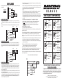
5-WIRE REVERSING POLARITY TYPE:
The Micro DLR4HD remote control is a multi-channel,
4-button controller, capable of a variety of functions. This guide will describe its
operation and serve as a quick reference manual.
WIRING GUIDE (CONT.):
HOW TO “CODE LEARN” A REMOTE CONTROL:
1) Turn ignition to the “on” position. Press emergency override button 5 times. The led will flash a total of 6 times then stay solid. The unit is now in code learning mode.
2) Once (1) is done, the parking lights and led will remain solid for about 10 seconds before
exiting from code learning mode.
3) While the parking lights and led are solid, press any of 4 buttons on the remote control. The parking lights will shut off momentarily. This will confirm that the remote has been
programmed. The led will flash up to 4 times depending on how many remotes will
be programmed (up to 4) confirming the new code. Then the led will light solid again,
awaiting the next remote to be programmed.
4) A total of 4 remotes can be programmed into the unit. If there is more than 1 remote
being programmed, you will need to repeat step (3).
5) Once all of the remotes have been programmed into the system and ignition is shut off,
the unit will exit from code learning mode. Both led and parking lights will shut off.
ONE-TOUCH EMERGENCY OVERRIDE:
To activate override, the system must be armed. Turn ignition on, then press override
switch one time. The system will disarm. Note: this is not a “valet” feature. This is
simply an emergency override.
HIJACK FUNCTION:
7) GRAY: (-) 500MA AUXILIARY OUTPUT #1 (TRUNK POP OR REMOTE START)
Provides an one-time momentary negative output (optional) for trunk pop, remote start,
windows roll up, etc.
8) GRAY/WHITE: (-) 500MA AUXILIARY OUTPUT #2 (UNLOCK 2)
This can be used for driver door priority door lock systems. Simply press “unlock”
button twice to activate “unlock 2”, activating remaining passenger doors.
9) DOOR LOCK HARNESS FOR ON-BOARD RELAYS
10) ORANGE/BLACK: (-) 500MA DOMELIGHT SUPERVISION OUTPUT
This wire allows you to turn on the vehicle’s domelight for 30 sec. when you unlock
your vehicle with keyless entry. (SEE DIAGRAM)
4) YELLOW: +12 VOLT SWITCHED IGNITION
Find the wire that supplies positive 12v to the parking lights only. This wire is
located at the headlight/parking light switch or the light itself. DO NOT CONNECT
THE HEADLIGHT WIRE OR THE UNIT WILL BE DAMAGED! Vehicles with
indepedent left and right signal systems must use relay (Part# 5001) for proper
operation.
5) BROWN: (-) 500MA SIREN/HORN HONK OUTPUT (SELECTABLE)
This wire should be connected to the vehicle’s (-) horn trigger switch wire coming from
steering column. Some vehicles may require relay to provide a stronger (-) pulse.
15 Amp FUSE
15 Amp FUSE
RED
(+)12 VDC
(OPTIONAL)
BLACK
GROUND
(+/-) PARKING LIGHT OUTPUT
STARTER
WHITE
YELLOW
IGNITION (+)
KILLER
SELECT JUMPER *P9
ORANGE/BLK
(-)DOMELIGHT
BROWN
(-)CAR HORN / (-)SIREN
ORANGE
(-)STARTER DISABLE
GREY
(-)50mA AUXILIARY OUTPUT "1" (TRUNK
OR R STARTER)
GREY/WHITE
(+) OR (-) DEPENDS ON DOME LIGHT CIRCUIT TYPE
STARTER
SOLENOID
SELECT JUMPER #8
(-)500mA AUXILIARY OUTPUT "2" (UNLOCK2)
87
KEYLESS
ORANGE/BLACK (-)
85
87A
86
(+) CONSTANT (+) 12 VOLTS
FUSE AT 3.5AMPS
BROWN/BLACK
30
1) RED: MAIN + 12 VOLT POWER
Connect the red fused wire to a constant 12v positive source. Micro recommends direct
connection to the battery. Be sure to fuse this wire. An amp atc fuse and holder are
provided for this. Be sure all connections are fully insulated.
3) WHITE (+/-) 12 VOLT PARKING LIGHT OUTPUT (SELECTABLE)
Find the wire that supplies switched positive 12v to the ignition. This wire is usually
located in the steering column harness. This wire will have positive 12v when key is in
ignition position and when starter is cranking. Note: For Neg. Output, Change Jumper 9.
JP9
WARNING: Do not connect the orange/black wire directly to the Dome-Light circuit or
WIRE
severe damage will occur to theORANGE/BLACK
unit.
• To disable HIJACK, press “unlock” before 60 sec.
• After 60 sec. to disable HIJACK, press override switch.
• To drive with HIJACK mode, press “unlock” before 60 sec. 2) BLACK: GROUD
Connect to the negative terminal of the battery or to a solid chassis ground. Improper
grounding will cause malfunctions. Be sure ground is clean and well insulated.
W/ JUMPER (+) PARKING LAMP (15Amp)
W/ JUMPER (-) PARKING LAMP (500mA)
• This output will reset if the keyless entry is locked/unlocked or if the vehicle’s ignition is turned on.
WIRING GUIDE:
DLR4HD WIRING DIAGRAM:.
6) ORANGE: (-) STARTER DISABLE OUTPUT
Find the starter solenoid wire, usually located in the steering column harness. This will
show positive 12v only when starter is cranking. This wire must be cut and connected
to a relay. When cut, motor should not start. See starter disable circuit for wiring
instruction.
TO DOME LIGHT
PROGRAMMABLE JUMPER OPTIONS:
Pin#
PIN IN (*default)
N/C
BLUE/BLACK
Pin REMOved
1
ARM/DISarm horn honk on*
Arm disarm horn honk off
2
arm/disarm horn honk .5 sec. pulse* arm/disarm horn honk 1 sec. pulse
3
n/a
4
ignition auto lock/unlock*
disable ignition auto lock/unlock
5
normal door locks (1.75 sec)*
vacuum door locks (3 sec)
6
normal lock/unlock*
double pulse lock/unlock
7
disable ignition HI-jack*
ignition HI-jack n/a
8
SIREN
HORN
NOTE: YOU MUST POWER DOWN UNIT BEFORE CHANGING ANY OF THE
JUMPER PIN SETTINGS.
RED/BLACK
N/O
WHITE/BLACK
N/C
GREEN/BLACK
15 Amp FUSE
VIOLET/BLACK
COM
UNLOCK
COM
LOCK
N/O
LED
OVERRIDE SWITCH