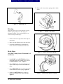
1
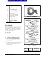
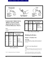
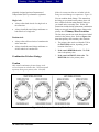
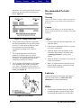
Directory Previous Previous Next Search Exit Cam Brakes Table of Contents Sub-Headings Introduction 3 Q Plus™ 3 Disassembly 4 Remove the Wheel Components 4 Automatic Slack Adjuster 4 Brake Shoes 5 Remove Camshaft/Auto Slack Adjuster 6 Preparing Parts for Assembly 6 Clean and Dry Parts 7 Corrosion Protection 7 Inspect Parts 7 Automatic Slack Adjuster 8 Brake Camshafts 9 Assembly 9 Install Camshaft 9 Q Series 16.5-Inch Cam Brake 10 Shoe Return Spring Installation 11 Automatic Slack Adjuster 11 Handed and Unhanded Slack Adjusters 11 Pull Pawls 11 Replace Conventional Pawls 12 Installing Slack Adjuster onto Camshaft 12 Install the Clevis 13 Slack Adjuster with Threaded Clevis 13 Brake Slack Adjuster Position Method 14 Install the Brake Shoes 14 All Q Plus™ and Q Series 16.5 14 Q Series 15-Inch Cam Brake 15 Drum and Wheel 16 Adjusting the Brakes 16 Automatic Slack Adjuster 16 Measure the Automatic Slack Adjuster 16 Adjust the Brake 17 Free Stroke Measurement 17 CVSA Guidelines to Measure 18 Alternate Method to Determine Push Rod 19 Relining the Brakes 19 Single or Tandem Axle 19 Use the Correct Lining Material 20 All American Cam Brakes Combination Friction Linings 20 Primary Shoe Locations 20 Lubrication and Maintenance 21 Camshaft Bushings 21 On-Highway Linehaul Applications 21 Off-Highway Linehaul Applications 21 Automatic Slack Adjuster Maintenance 21 Anti-Seize Compound 22 Inspection 23 Before You Return the Vehicle to Service 23 Recommended Periodic Service 23 Cam Brake Tips 25 List of Figures Figure 1—15/16.5 Q Plus™ and Q Series 2 Figure 1a—Q Plus Brakes 3 Figure 2—Components 3 Figure 3—Pawls 4 Figure 4—Adjusting Nut 5 Figure 5—Bottom Cam Roller 5 Figure 6—Bottom Shoe Return Spring 5 Figure 7—Bottom Shoe Retainer Spring 5 Figure 8—Radial Free Play Movement 6 Figure 9—Drum Diameter 8 Figure 10—Adjusting Nut Torque 8 Figure 11—Spider Bolt Torque 9 Figure 12—Seal Driver 9 Figure 13—Seal Lips 9 Figure 14—Camshaft Installation 10 Figure 15—Standard Q Plus™ Cam 10 Figure 16—Hammerclaw Cam 11 Figure 17—Brake Adjustment Gap 11 Figure 18—Offset Return Spring 11 Figure 19—Handed/Unhanded Adjusters 12 Figure 20—Slack Adjuster Installation 13 Figure 21—Retainer Clips/Clevis Pins 13 Figure 22—Clevis Position 14 Figure 23—Threaded Clevis 14 Figure 23a—BSAP Dimension 14 Figure 24—Retaining Spring Installation 15 1 Directory Previous Previous Next Figure 25—Return Spring Installation Figure 26—Cam Roller Installation Figure 27—Cam Roller Retainer Figure 28—Q Series Springs Figure 29—Slack Adjuster Template Figure 30—Brake Adjustment Figure 31—Free Stroke Figure 32—Stroke Adjustment Search 15 15 15 16 16 17 17 18 Exit Figure 33—Brake Adjustment Guidelines 19 Figure 34—Primary/Secondary Brake Shoes 21 Figure 35—Linings and Drums 23 Figure 36—Free Stroke 23 Figure 37—Fastener Torque for Cam Brakes 25 Cam Brakes Exploded View Figure 1—15 and 16.5 Q Plus and Q Series Brakes Exploded View Item 2 Description 1 Shoe and Lining Assembly 2 Spring –shoe retaining 3 Bushing – anchor pin 4 Anchor Pin – brake shoe 5 Camshaft – “S” head 6 Snap Ring – anchor pin 7 Washer – camhead 8 Seal – camshaft (grease) 9 Bushing – camshaft 10 Roller – brake shoe All American Cam Brakes Directory Previous Previous Next 11 Pin – return spring 12 Spring – brake shoe return 13 Cast spider – brake 14 Seal – chamber bracket 15 Bracket – camshaft and chamber 16 Capscrew – chamber bracket 17 Fitting – grease 18 Washer – camshaft (thick) 19 Slack Adjuster – automatic 20 Washer – spacing 21 Snap Ring – camshaft 22 Dust Shield 23 Capscrew – dust shield 24 Plug Search Exit Figure 1a—Q Plus Brakes Introduction Meritor cam brakes are-air actuated, cam operated, two-shoe brakes with each shoe mounted on a separate anchor pin. The brakes are available with automatic or manual slack adjusters and can be assembled with spring brakes. Q Plus™ • More lining thickness increases service life and mileage between relines. • A redesigned S-cam and heavy-duty shoe return spring allow additional shoe travel. • An improved camshaft bushing contributes to longer service life. • The trailer axle version of the 16.5 x 7.0-inch Q Plus™ brake uses a heavy-duty, bolt-on camshaft bushing. Figure 2—Components All American Cam Brakes Camshafts Shoes Return Springs Q Plus Q Plus Heavy-duty (blue) 3 Directory Previous Previous Next Search Disassembly Remove the Wheel Components Warning Asbestos and Non-Asbestos Fibers. Some brake linings contain asbestos fibers, a cancer and lung disease hazard. Some brake linings contain non-asbestos fibers, whose longterm effects to health are unknown. You must use caution when you handle both asbestos and nonasbestos materials. Warning To prevent serious eye injury, always wear safe eye protection when you perform vehicle maintenance and service. Warning Block the wheels to prevent the vehicle from moving. Support the vehicle with safety stands. Do not work under a vehicle supported only by jacks. Jacks can slip or fall over. Serious personal injury can result. Exit Automatic Slack Adjuster For complete maintenance and service information on Meritor’s automatic slack adjuster, refer to “Automatic Slack Adjuster” section of this manual. Caution You must disengage a pull pawl or remove a conventional pawl before rotating the manual adjusting nut, or you will damage the pawl teeth. A damaged pawl will not allow the slack adjuster to automatically adjust brake clearance. Replace damaged pawls before putting the vehicle in service. 1. If the slack adjuster is equipped with a conventional pawl, remove the pawl. Figure 3. If the slack adjuster is equipped with a pull pawl assembly, use a screwdriver or an equivalent tool to lift the pawl button at least 1/32-inch from the actuator to disengage the pawl. Figure 3. 1. The vehicle must be on a level surface. 2. Put blocks under the wheels that will not be raised to keep the vehicle from moving. 3. Raise the vehicle, so that the area you will service is off the ground. Support the vehicle with safety stands. Warning When you work on a spring chamber, carefully follow the service instructions of the chamber manufacturer. Sudden release of a compressed spring can cause serious personal injury. Figure 3—Pawls 2. Use a wrench to turn the manual adjusting nut in the direction shown in Figure 4 until the brake shoes are fully retracted and the drum clears the lining. 4. If the brake has spring chambers, carefully cage and lock the spring, so that the spring cannot actuate during assembly. 4 All American Cam Brakes Directory Previous Previous Next Search Exit 5. Remove the shoe retainer springs and the brake shoes. Figure 4—Adjusting Nut Warning When you remove a clevis pin that has a spring, hold the spring with pliers. The spring can disengage from the clevis with enough force to cause serious personal injury. Figure 5—Bottom Cam Roller 3. Remove both clevis pins and retainer clips or cotter pins. 4. Move the slack adjuster away from the clevis. 5. Follow the manufacturer's instructions to remove the wheel and drum from the axle. Brake Shoes Figure 6—Bottom Shoe Return Spring All Q Plus™ and Q Series 15-lnch and 16.5lnch Brakes 1. Push DOWN on the BOTTOM brake shoe. Pull on the cam roller retainer clip to remove the BOTTOM cam roller. Figure 5. 2. Lift the TOP brake shoe and pull on the cam roller retainer clip to remove the TOP cam roller. 3. Lift the BOTTOM shoe to release the tension on the brake shoe return spring. Figure 6. 4. Rotate the BOTTOM shoe to release the tension on the brake shoe retainer springs. Figure 7. All American Cam Brakes Figure 7—Bottom Shoe Retainer Spring 5 Directory Previous Previous Next Search Exit and the clevis collar exceeds 0.060-inch (1.52mm). You do not have to remove the clevis if it is in good condition. Remove the Camshaft and Automatic Slack Adjuster 4. Remove the slack adjuster from the camshaft. Note Meritor recommends that you check camshaft bushing end play at every reline to verify that end play is within specification. 1. At the first reline, inspect the cam-to-bushing radial free play and axial end play. Radial free play movement must be less than 0.030-inch (0.762 mm). Figure 8. 5. Remove the camshaft from the spider. 6. Use the correct size driver to remove the camshaft bushings from the spider and the spider bracket. Preparing Parts for Assembly Warning To prevent serious eye injury, always wear safe eye protection when you perform vehicle maintenance or service. Warning Figure 8—Radial Free Play Movement • • • Solvent cleaners can be flammable, poisonous and cause burns. Examples of solvent cleaners are carbon tetrachloride, emulsion-type cleaners and petroleum-based cleaners. To avoid serious personal injury when you use solvent cleaners, you must carefully follow the manufacturer's product instructions and these procedures: If radial free play movement is less than 0.030-inch (0.76 mm): Do not replace the bushings and seals. • Wear safe eye protection. • Wear clothing that protects your skin. If radial free play movement exceeds 0.030-inch (0.76 mm): Replace the bushings and seals. • Work in a well-ventilated area. • Do not use gasoline, or solvents that contain gasoline. Gasoline can explode. If axial end play exceeds 0.030-inch (0.76 mm): Remove the snap ring. Add the appropriate number of spacing washers between the automatic slack adjuster and the snap ring to achieve between 0.005inch and 0.030-inch (0.127-0.762 mm) axial free play movement. • You must use hot solution tanks or alkaline solutions correctly. Follow the manufacturer's instructions carefully. 2. Remove the snap ring, washers and spacers from the camshaft. Caution Do not use hot solution tanks or water and alkaline solutions to clean ground or polished parts. Damage to parts will result. 3. If the slack adjuster is equipped with a "Quick Connect" clevis: Remove the clevis from the push rod if the gap between the clevis 6 All American Cam Brakes Directory Previous Previous Next Search Clean and Dry Parts 1. Use soap and water to clean non-metal parts. 2. Use soft paper or cloth that is free from dirt, oil or abrasives to dry the parts completely. 3. Dry parts immediately after cleaning with clean paper or rags, or compressed air. Corrosion Protection Note Parts must be clean and dry before you lubricate them. 1. If you assemble parts immediately after you clean them: Lubricate parts with grease to prevent corrosion. Parts must be clean and dry before you lubricate them. 2. If you store parts after you clean them: Apply a corrosion-preventive material. Store parts in a special paper or other material that prevents corrosion. Inspect Parts It is important to carefully inspect all parts before assembly. Check all parts for wear or damage. Repair or replace them as required. 1. Check the spider for expanded anchor pin holes and for cracks. Replace damaged spiders and anchor pin bushings. 2. Check the camshaft bracket for broken welds, cracks and correct alignment. Replace damaged brackets. Exit On 16.5-inch brake shoes only: Anchor pin holes must not exceed 1.009-inches (25.63 mm) in diameter. The distance from the center of the anchor pin hole to the center of the roller hole must not exceed 12.779-inches (32.46 cm). Replace any shoe with measurements that do not meet specifications. 5. Check the camshaft for cracks, wear and corrosion. Check the cam head, bearing journals and splines. Replace damaged camshafts. Warning Do not operate the vehicle with the brake drum worn or machined beyond the discard dimension indicated on the drum. The brake system may not operate correctly. Damage to components and serious personal injury can result. 6. Check the drums: a. Check the brake drums for cracks, severe heat checking, heat spotting, scoring, pitting and distortion. Replace drums as required. Meritor recommends that you do NOT turn or rebore brake drums because it decreases the strength and heat capacity of the drum. b. Measure the inside diameter of the drum in several locations with a drum caliper or internal micrometer. Figure 9. Replace the drum if the diameter exceeds the specifications supplied by the drum manufacturer. 7. Check dust shields for rust and distortion. Repair or replace damaged shields as necessary. 3. Check anchor pins for corrosion and wear. Replace damaged anchor pins. 4. Check brake shoes for rust, expanded rivet holes, broken welds and correct alignment. Replace a shoe with any of the above conditions. All American Cam Brakes 7 Directory Previous Previous Next Search Exit If the torque value remains less than 25 lb-in (2.8 N•m): The slack adjuster is working correctly. If the torque value exceeds 25 lb-in (2.8 N•m): The slack adjuster is not working correctly. Disassemble the slack adjuster. • Check that the slack adjuster is assembled correctly. • Check that parts are aligned correctly. Figure 9—Drum Diameter Automatic Slack Adjuster 1. For slack adjusters with a “Quick Connect” clevis: Check the gap between the clevis and the collar. If the gap exceeds 0.060-inch (1.52 mm), replace the clevis with a one-piece threaded clevis design. 2. Check the clevis pins and the bushing in the arm of the slack adjuster. Replace the pins if they are worn. Replace the bushing if its diameter exceeds 0.531-inch (13.5 mm). Caution Figure 10—Adjusting Nut Torque Note Do not seal the boot to the tapered part of the actuator rod. • If the rod has a groove: The top of the boot must fit into the groove. • If the rod does not have a groove: Use silicone sealant to seal the top of the boot to the round part of the rod. You must disengage a pull pawl or remove a conventional pawl before rotating the manual adjusting nut, or you will damage the pawl teeth. A damaged pawl will not allow the slack adjuster to automatically adjust brake clearance. Replace damaged pawls before putting the vehicle in service. 5. Fasten the bottom of the boot to the housing with a retaining clamp. 3. Use a torque wrench that measures lb-in. 6. Conventional Pawl: Install the pawl assembly into the housing. Tighten the capscrew to 1520 lb-ft (20-27 N•m). 4. To turn the adjusting nut in the direction shown in Figure 10, read the torque scale and rotate the gear 360 degrees (22 turns of the wrench). 7. Pull Pawl: Remove the screwdriver or equivalent tool. The pull pawl will re-engage automatically. The torque value must remain less than 25 lb-in (2.83 N•m) during the complete 360-degree rotation of the gear. 8 8. Use a grease gun to lubricate the slack adjuster through the grease fitting. If necessary, install All American Cam Brakes Directory Previous Previous Next Search Exit a camshaft into the slack adjuster gear to minimize grease flow through the gear holes. 9. Apply lubrication that meets Meritor's specifications until new grease purges from around the camshaft splines and from the pawl assembly. Refer to “Lubrication and Maintenance” section of this manual. Brake Camshafts Figure 12—Seal Driver Note Meritor recommends that you install new camshaft bushings whenever you install a new camshaft. 1. Tighten all of the spider bolts to the correct torque as shown in Figure 11. Figure 13—Seal Lips Figure 11—Spider Bolt Torque 2. Use a seal driver to install new camshaft seals and new bushings in the cast spider and the camshaft bracket. If equipped with a stamped spider, install both bushings into the bracket. Figure 12. Install the seals with the seal lips TOWARD the automatic slack adjuster. Figure 13. 3. If the camshaft bracket was removed: Install the chamber bracket seal and bracket onto the spider. Tighten the capscrews to the torque specified in the “Fastener Torque Table for Cam Brakes”. Assembly Install the Camshaft Warning Asbestos and Non-Asbestos Fibers. Some brake linings contain asbestos fibers, a cancer and lung disease hazard. Some brake linings contain non-asbestos fibers, whose longterm effects to health are unknown. You must use All American Cam Brakes 9 Directory Previous Previous Next Search caution when you handle both asbestos and nonasbestos materials. Warning To prevent serious eye injury, always wear safe eye protection when you perform vehicle maintenance or service. 1. Install the cam head thrust washer onto the camshaft. Apply 0-617-A or 0-617-8 grease to the camshaft bushings and journals. 2. Install the camshaft through the spider and bracket so that the camshaft turns freely by hand. Figure 14. Exit Replacing a Hammerclaw Camshaft with a Standard Q Plus™ Camshaft on Front Axles Only Warning Do not use the straight-center bar shoe return spring with the Q Plus™ camshaft. The shoe spring can interfere with the camshaft and affect braking performance. Serious personal injury can result. Caution Only install a Q Plus™ camshaft in a Q Plus™ brake. A Q Series hammerclaw camshaft will not provide enough clearance between the brake shoe and the brake drum. Brake drag and damage to components can result. To install a new brake drum so that it fits correctly over a Q Plus™ brake shoe, you must install a Q Plus™ camshaft. Damage to components can result. Figure 14—Camshaft Installation Q Series 16.5-lnch Cam Brake A standard Q Plus™ camshaft and a shoe return spring with an offset center bar replaces the hammerclaw Q Series camshaft and shoe return spring with a straight center bar on 16.5 x 5-inch and 6-inch Q Series cam brake. Figure 15 and Figure 16. Replacing a Q Series Camshaft with Q Plus™ Camshaft in all Front and Drive Axle 16.5-lnch Q Series Brakes Meritor has implemented a replacement of the Q Series camshaft with the Q Plus™ camshaft in aIl 16.5-inch Q Series brakes. Q Series brake installation and maintenance procedures are not affected by the replacement. Figure 15—Standard Q Plus Cam 10 All American Cam Brakes Directory Previous Previous Next Search Exit Shoe Return Spring Installation Install the new offset shoe return spring with the open end of the spring hooks toward the camshaft. Figure 18. Figure 16—Hammerclaw Cam A Q Plus™ camshaft has deeper roller pockets than a Q Series camshaft and has "Q Plus" forged into one of the pockets. You may notice a larger gap between the brake lining and the drum after you assemble the brake shoe and shoe return spring with an offset center bar. The excess gap will be eliminated when you correctly adjust the brake. Figure 17. Refer to “Adjust the Brake” section of this manual. 1. Follow Steps 1-2 to replace a Q Series hammerclaw camshaft with a standard Q Plus™ camshaft in a 16.5-inch Q Series brake. 2. Continue to follow service and maintenance procedures for a Q Plus™ camshaft and Q Series brake. Figure 18—Offset Return Spring Automatic Slack Adjuster Note As of January 1993, some parts of Meritor's automatic slack adjuster are no longer serviceable and are not interchangeable with parts from earlier models. Refer to “Adjusting the Brakes" section of this manual. Handed and Unhanded Automatic Slack Adjusters There are two automatic slack adjuster designs: HANDED and UNHANDED. For most applications, install a handed automatic slack adjuster so that the pawl faces INBOARD on the vehicle. The pawl can be on either side or on the front of the slack adjuster housing. Figure 19. Figure 17—Brake Adjustment Gap All American Cam Brakes 11 Directory Previous Previous Next Search Exit Pull Pawls 1. Check the camshaft, bushings and seals for wear and corrosion. Pull pawls are spring loaded. Pry the pull pawl at least 1/32-inch to disengage the teeth. Figure 19B. When you remove the pry bar, the pull pawl will reengage automatically. 2. Turn the camshaft by hand to check for smooth operation. Replace Conventional Pawls with Pull Pawls When you service an automatic slack adjuster, replace a conventional pawl with a pull pawl. Figures 19A and 19B. Install the slack adjuster so that you can remove the conventional pawl or disengage the pull pawl when you adjust the brake. 3. Repair or replace parts as required. 4. Apply the service brake and spring brake several times. Check that the chamber return spring retracts the push rod quickly and completely. If necessary, replace the return spring or the air chamber. 5. The new automatic slack adjuster must be the same length as the one you are replacing. Table A shows the length of slack adjuster that is used with each brake chamber size. 6. Place blocks in front of and behind the vehicle's wheels to prevent it from moving. Length of Slack Size of Chamber Adjuster (Inches) (Square Inches) 5 9*, 12*, 16, 20, 24, 30, 5-1/2 9*, 12*, 16, 20, 24, 30, 36 6 24, 30, 36 6-1/2 30, 36 * Use an auxiliary spring on slack adjusters used with these size chambers. A size 9 or 12 chamber return spring cannot supply enough spring tension to completely retract the slack adjuster Table A—Chamber and Automatic Slack Adjuster Sizes Figure 19—Handed and Unhanded Slack Adjusters Installing the Slack Adjuster Onto the Camshaft Warning Block the wheels to prevent the vehicle from moving. Support the vehicle with safety stands. Do not work under a vehicle supported only by jacks. Jacks can slip and fall over. Serious personal injury can result. 12 Warning When you work on a spring chamber, carefully follow the service instructions of the chamber manufacturer. Sudden release of a compressed spring can cause serious personal injury. 7. If the brake has a spring brake, compress and lock the spring to completely release the brake. No air pressure must remain in the service half of the air chamber. All American Cam Brakes Directory Previous Previous Next Search Exit Caution Most Meritor automatic slack adjusters manufactured after January 1990 have lubrication holes in the gear splines. Do not operate the actuator before you install the slack adjuster. Lubricant can pump through the holes and onto the splines. Damage to components can result. 8. If the automatic slack adjuster gear has a 10tooth spline, apply anti-seize compound to the slack adjuster and cam splines. Use Meritor specified 0-637, Southwest SA 8249496 or equivalent lubricants. Figure 20—Slack Adjuster Installation Note Install the slack adjuster so that you can remove a conventional pawl or disengage a pull pawl when you adjust the brake. 9. Install the slack adjuster onto the camshaft. Position the slack adjuster so that you can remove the pawl when you adjust the brake. 10. If necessary, install spacing washers and the snap ring at a maximum clearance of 0.062inch (1.57 mm). 11. Install the clevis onto the push rod. Do not tighten the jam nut against the clevis. Caution You must disengage a pull pawl before rotating the manual adjusting nut, or you will damage the pawl teeth. A damaged pawl will not allow the slack adjuster to automatically adjust the brake clearance. Replace damaged pawls before returning the vehicle to service. 12. Disengage the pawl. Turn the manual adjusting nut to align the holes in the slack adjuster arm and the clevis. Figure 20. All American Cam Brakes Install the Clevis A Slack Adjuster with a Welded Clevis Caution Always replace used clevis pin retainer clips with new ones when servicing the automatic slack adjuster or chamber. Do not reuse clevis pin retainer clips after removing them. Discard used clips. When removed for maintenance or service, clevis pin retainer clips can be bent or "gapped apart" and can lose retention. Damage to components can result. 1. Check the clevis position. Apply anti-seize compound to the two clevis pins. Install the clevis pins through the clevis and the slack adjuster. 2. Install new cotter pins or clevis pin retainer clips to hold the clevis pins in place. Figure 21. 13 Directory Previous Previous Next Search Exit • Thread engagement between the clevis and the push rod must be at least 1/2-inch (12.7 mm). Figure 23. • The push rod must not extend through the clevis more than 1/8-inch (3.18 mm). If necessary, cut the push rod, or install a new push rod with a new air chamber. 5. Tighten the jam nut against the clevis to torque specifications in Table B. Figure 21—Retainer Clips and Clevis Pins A Slack Adjuster with a Threaded Clevis 1. Install the large clevis pin through the large holes in the template and the clevis. 2. Select the hole in the template that matches the length of the slack adjuster. Hold that hole on the center of the camshaft. 3. Look through the slot in the template. If necessary, adjust the position of the clevis until the small hole in the clevis is completely visible through the template slot. Figure 22. Figure 23—Threaded Clevis Threads 1/2 - 20 5/8 - 18 Torque 20-30 lb-ft (27-41 N•m) 35-50 lb-ft (48-68 N•m) Table B—Jam Nut Torque Specifications Brake Slack Adjuster Position (BSAP) Method When installing the automatic slack adjuster, verify that the BSAP dimension of the chamber matches the table in Figure 23a. Figure 22—Clevis Position 4. Check for these specifications: 14 All American Cam Brakes Directory Previous Previous Next Search Exit Figure 24—Retaining Spring Installation 2. Rotate the LOWER brake shoe FORWARD. Install a new brake shoe return spring with the OPEN end of the spring hooks TOWARD the camshaft. Figure 25. Figure 23a—BSAP Dimension Install the Brake Shoes Note To help ensure maximum lining life, Meritor recommends that you replace springs, rollers, anchor pins and cam bushings at each reline. All Q Plus™ and Q Series 16.5lnch Brakes 1. Place the UPPER brake shoe into position on the TOP anchor pin. Hold the LOWER brake shoe on the BOTTOM anchor pin. Install two new brake shoe retaining springs. Figure 24. All American Cam Brakes Figure 25—Return Spring Installation 3. Pull each brake shoe AWAY from the cam to permit enough space to install the cam roller and cam roller retainer. Press the "ears" of the retainer to permit it to fit between the brake shoe webs. Figure 26. 15 Directory Previous Previous Next Search Exit camshaft. Install the shoes on the anchor pins. Figure 28. Figure 26—Cam Roller Installation 4. Push the cam roller retainer into the brake shoe until its "ears" lock in the shoe web holes. Figure 27. 5. Lubricate the brake components. Refer to “Lubrication and Maintenance” section for lubrication specifications. Figure 28—Q Series Springs 3. Hold the BOTTOM shoe in position. Install the shoe return spring. 4. Pull the brake shoe AWAY from the cam to permit enough space to install the cam roller and cam roller retainer. 5. Lubricate the brake components. Refer to “Lubrication and Maintenance” section for lubrication specifications. Drum and Wheel Follow the manufacturer’s instructions to install the drum and wheel onto the axle. Figure 27—Cam Roller Retainer Q Series 15-lnch Cam Brake 1. Install the anchor pins, washers and nuts to the spider if these parts were previously removed. Tighten the anchor pin nuts to a torque of 325375 lb-ft (441-509 N•m). Adjusting the Brakes Automatic Slack Adjuster Warning To prevent serious eye injury, always wear safe eye protection when you perform vehicle maintenance or service. 2. Install a new brake shoe return spring with the OPEN end of the spring hooks TOWARD the 16 All American Cam Brakes Directory Previous Previous Next Search Exit Measure the Automatic Slack Adjuster Caution There are three Meritor automatic slack adjuster installation templates for drum brakes: Truck or tractor, trailer and coach. These templates are NOT interchangeable. You must use the correct template and adjust the clevis position as described in this section. If you use the wrong template and install the clevis in an incorrect position, the automatic slack adjuster will not correctly adjust the brake. If the slack adjuster under-adjusts the brake, stopping distances will be increased. If the slack adjuster over-adjusts the brake, the linings can drag and damage the brake. Note For long-stroke chambers, use the Brake Slack Adjuster Position method to measure the automatic slack adjuster. 1. If necessary, order the correct automatic slack adjuster template from Meritor's Customer Service Center at 800-535-5560. 2. Use the correct Meritor automatic slack adjuster template to measure the length of the slack adjuster. The marks by the holes in the small end of the template indicate the length of the slack adjuster. Figure 29. Figure 29—Slack Adjuster Template Adjust the Brake Free Stroke Measurement Caution You must disengage a pull pawl or remove a conventional pawl before rotating the manual adjusting nut, or you will damage the pawl teeth. A damaged pawl will not allow the slack adjuster to automatically adjust brake clearance. Replace damaged pawls before putting the vehicle in service. Note During preventive maintenance on an in-service brake, check both the free stroke as described below and the adjusted chamber stroke as described in “Alternate Method for Determining Push Rod Travel (Adjusted Chamber Stroke)” section of this manual. On some applications, you may find the in-service free stroke to be slightly longer than specified in Step 5. However, this is not necessarily a concern, as long as the adjusted chamber stroke is within the All American Cam Brakes 17 Directory Previous Previous Next Search limits shown in the “Commercial Vehicle Safety Alliance (CVSA) Reference Charts”. 1. Disengage a pull pawl or remove a conventional pawl. 2. Turn the adjusting nut in the direction shown in Figure 30 until the linings touch the drum, and then turn the adjusting nut 1/2 turn in the opposite direction. Exit brakes). Measure the same distance again while the brakes are applied. Refer to "Y" in Figure 31. Caution Do not set FREE STROKE shorter than specifications. If FREE STROKE is too short, linings can drag and damage the brake. 5. The difference between measurement "X" and measurement "V" is the free stroke, which sets the clearance between the linings and drum. Free stroke must be within 1/2-inch - 5/8-inch (12.7-15.9 mm) for drum brakes. Figure 31. 6. If it is necessary to adjust the stroke, turn the adjusting nut 1/8 turn in the direction shown in Figure 32 and check the stroke again. Continue to measure and adjust the stroke until it is adjusted correctly. Figure 30—Brake Adjustment 3. Measure the distance from the center of the large clevis pin to the bottom of the air chamber while the brake is released. Refer to "X" in Figure 31. Figure 32—Stroke Adjustment 7. Release a pull pawl or install a conventional pawl. Warning Figure 31—Free Stroke When you work on a spring chamber, carefully follow the service instructions of the chamber manufacturer. Sudden release of a compressed spring can cause serious personal injury. 4. Use a pry bar to move the slack adjuster so that the linings are against the drum (applying the 18 All American Cam Brakes Directory Previous Previous Next Search 8. If the brake has spring chambers, carefully release the spring. 9. Test the vehicle to ensure that the brake system is operating correctly before you return the vehicle to service. Commercial Vehicle Safety Alliance (CVSA) Guidelines to Measure Push Rod Travel (Adjusted Chamber Stroke) Use the following procedures to check in-service push rod travel (adjusted chamber stroke) on truck or tractor air brakes with automatic slack adjusters. Hold the ruler parallel to the push rod and measure as carefully as possible. An error in measurement can affect CVSA re-adjustment limits, which state that "any brake 1/4-inch or more past the readjustment limit, or any two brakes less than 1/4inch beyond the re-adjustment limit will be cause for rejection." Warning To prevent serious eye injury, always wear safe eye protection when you perform vehicle maintenance or service. Warning When you work on a spring chamber, carefully follow the service instructions of the chamber manufacturer. Sudden release of a compressed spring can cause serious personal injury. 1. The engine must be OFF. If the brake has spring chambers, carefully release the spring. 2. Check the gauges in the cab to ensure that air pressure in the tanks is 100 psi (689 kPa). Exit 4. With the brakes released, mark the push rod where it exits the chamber. Figure 33. Measure and record the distance. 5. Have another person apply and hold the brakes one full application. Figure 33. 6. Measure push rod travel distance (adjusted chamber stroke) from where the push rod exits the brake chamber to your mark on the push rod. Measure and record the distance. Figure 33. 7. To determine push rod travel (adjusted chamber stroke): Subtract the measurement you obtained in Step 4 from the measurement you obtained in Step 6. The difference is the push rod travel (adjusted chamber stroke). a. Push rod travel (adjusted chamber stroke) must not be greater than the stroke length shown in the CVSA reference charts for the size and type of air chamber you are inspecting. b. If push rod travel (adjusted chamber stroke) is greater than the maximum stroke shown in the CVSA reference charts, inspect the slack adjuster and replace it if necessary. Alternate Method for Determining Push Rod Travel (Adjusted Chamber Stroke) Use the above procedure, except in Step 4 and Step 6, measure the distance from the bottom of the air chamber to the center of the large clevis pin on each of the brakes. 3. Determine the size and type of brake chamber you are inspecting. All American Cam Brakes 19 Directory Previous Previous Next Search Exit Figure 33—Brake Adjustment Guidelines (CVSA) Commercial Vehicle Safety Alliance (CVSA) North American Out-of-Service Criteria Reference Charts Note A brake found at the adjustment limit is not a violation. Type Outside Diameter (inches) Brake Adjustment Limit (inches 6 4-1/2 1-1/4 9 5-1/4 1-3/8 12 5-4/16 1-3/8 16 6-3/8 1-3/4 20 6-25/32 1-3/4 24 7-7/32 1-3/4 30 8-3/32 2 36 9 2-1/4 Should be as short as possible without lining to drum contact Table C—"Standard Stroke" Clamp-Type Brake Chamber Data Type Outside Diameter (inches) Brake Adjustment Limit (inches 16 6-3/8 2.0 20 6-25/32 2.0 24 7-7/32 2.0 24* 7-7/32 2.5 30 8-3/32 2.5 Should be as short as possible without lining to drum contact Table D—"Long Stroke" Clamp-Type Brake Chamber Data Outside Relining the Brakes Single or Tandem Axle Warning To prevent serious eye injury, always wear safe eye protection when you perform vehicle maintenance or service. Use the Correct Lining Material Note The drums and linings on the front axle do not have to be the same as the drums and linings on the rear axle. * For 3” maximum stroke type 24 chambers 20 Use the lining material that is specified by Blue Bird to help ensure that the brake will perform as All American Cam Brakes Directory Previous Previous Next Search originally designed and meet Department of Transportation (DOT) performance regulations. Single Axle • Always reline both wheels of a single axle at the same time. • Always install the same linings and drums on both wheels of a single axle. Exit follow the instructions that are included with the linings to avoid damage to components. Figure 34. You can combine brake linings. This means that the lining set you install on the primary shoe will have a different friction rating than the lining set you install on the secondary shoe. Follow the instructions included with replacement combination linings to correctly install the primary lining on the primary shoe. Primary Shoe Locations The first shoe past the cam in the direction of wheel rotation is the primary shoe. Refer to Figure 34 to determine primary and secondary shoe locations. Tandem Axle • Always reline all four wheels of a tandem axle at the same time. • Always install the same linings and drums on all four wheels of a tandem axle. Combination Friction Linings 1. The primary shoe can be at either the TOP or the BOTTOM position, depending on the location of the cam. 2. If the cam is BEHIND the axle: The TOP shoe is the primary shoe. 3. If the cam is in FRONT of the axle: The BOTTOM shoe is the primary shoe. Caution Only install combination friction linings in the correct location on a brake shoe. You must install a primary lining on a primary shoe. Carefully Figure 34—Primary and Secondary Brake Shoes All American Cam Brakes 21 Directory Previous Previous Next Search Exit Lubrication and Maintenance • During the first four month period: Inspect for hardened or contaminated grease and for the absence of grease every two weeks to determine lubrication intervals. Camshaft Bushings • Lubricate more often for severe-duty applications. Note Automatic Slack Adjuster Maintenance Meritor recommends that you install new camshaft bushings whenever you install a new camshaft. 1. Refer to Table E for grease specifications. Warning If grease flows from the seal near the cam head, replace the seal. Remove any grease or oil from the cam head, rollers and linings. Always replace contaminated linings. Grease on the linings can increase stopping distances. Serious personal injury and damage to components can result. Inspect and lubricate the slack adjuster according to one of the following schedules. Refer to Table F for grease specifications. Use the schedule that requires the most frequent inspection and lubrication. Also, inspect and lubricate the slack adjuster whenever you reline the brakes. The schedule of chassis lubrication used by your fleet. • The schedule of chassis lubrication recommended by the chassis manufacturer. • Every six months. 2. Lubricate through the fitting on the bracket or spider until new grease flows from the INBOARD seal. • A minimum of four times during the life of the linings. On-Highway Linehaul Applications Anti-Seize Compound • 1. Use anti-seize compound on the clevis pins of all slack adjusters. Q Plus™ and Q Series brakes: Every 100,000 miles (160,000 km). Off-Highway Applications • At least every four months when you replace the seals and reline the brakes. Components Retainer Clips Anchor Pins Roller (Journals Only) Camshaft Bushings When the brake is disassembled, or when necessary, lubricate the anchor pins and rollers 22 Meritor Specification 0-616-A 0-617-A or 0-617-B 0-645 NLGI Grade 1 1 2 2. Conventional automatic: Use anti-seize compound on the automatic slack adjuster and cam splines if the slack adjuster gear has no grease groove and holes around its inner diameter. Grease Description Clay Base Lithium 12Hydroxy Stearate or Lithium Complex Synthetic Oil, Clay Base Outside Temperature Down to -40°F (-40°C) Refer to the grease manufacturer's specifications for the temperature service limits. Down to -65°F (-54°C) All American Cam Brakes Directory where they touch the brake shoes. Do not allow grease to come in contact with the part of the cam roller that touches the cam head. Refer to the Warning above. Camshaft Splines Previous Previous Next Search 0-692 1 and 2 Any of Above 0-637* See Above 1 1/2 0-641 --- Exit Lithium Base Down to -40°F (-40°C) See Above Calcium Base Anti-Seize See Above Refer to the grease manufacturer's specifications for the temperature service limits Table E—Cam Brake Grease Specifications Component Meritor Specification NLGI Grade Grease Description Outside Temperature Automatic Slack Adjuster 0-616-A 1 Clay Base 0-692 1 and 2 Lithium Base 0-645 2 Synthetic Oil, Clay Base Down to -40°F (-40°C) Down t0 -40°F (-40°C) Down to -65°F (-54°C) Any of above 0-637 See Above 1 - 1/2 See Above Calcium Base Clevis Pins See Above Refer to the grease manufacturer's specifications for temperature service limits Table F—Automatic Slack Adjuster Grease Specifications *Do not mix Meritor grease specification 0-637 (part number 2297-U-4571), a calcium base, rust preventive grease, with other greases. The grease is also available as “Corrosion Control” (part number SA 8249496) from Southwest Petro-Chemical Division of Witco Chemical Corporation, 1400 S. Harrison, Olathe, KS 66061. Inspection Before You Return the Vehicle to Service 1. Check the complete air system for worn hoses and connectors. With air pressure at 100 psi, brakes released and engine off, loss of tractor air pressure must not exceed two psi a minute. Total tractor and trailer loss must not exceed three psi per minute. All American Cam Brakes 2. Check to see that the air compressor drive belt is tight. Air system pressure must rise to approximately 100 psi in two minutes. 3. The governor must be checked and set to the specifications supplied by the vehicle manufacturer. 4. Both the tractor and trailer air systems must match the specifications supplied by the vehicle manufacturer. 5. Both wheel ends of each axle must have the same linings and drums. All four wheel ends of tandem axles also must have the same linings 23 Directory Previous Previous Next Search and drums. It is not necessary for the front axle brakes to be the same as the rear driving axle brakes. Figure 35. Exit Recommended Periodic Service Warning To prevent serious eye injury, always wear safe eye protection when you perform vehicle maintenance or service. Caution Do not let brake lining wear to the point that the rivets or bolts touch the drum. Damage to the drum will occur. Figure 35—Linings and Drums 6. Always follow the specifications supplied by the vehicle manufacturer for the correct lining to be used. Vehicle brake systems must have the correct friction material and these requirements can change from vehicle to vehicle. 7. The return springs must retract the shoes completely when the brakes are released. Replace the return springs each time the brakes are relined. The spring brakes must retract completely when they are released. 8. The air chamber area multiplied by the length of the automatic slack adjuster is called the “AL" factor. This number must be equal for both ends of a single axle and all four ends of a tandem axle. Figure 36. Adjust 1. Correctly adjust the wheel bearings before you adjust the brakes. 2. Clean, inspect and adjust the brakes every time you remove a wheel hub. 3. Adjust the brakes when the chamber stroke exceeds the limits shown in the tables in the “Adjusting the Brakes” section of this manual. 4. Adjust the brakes as frequently as necessary for correct, safe operation. 5. When you adjust the brakes, check for correct lining-to-drum clearance, push rod travel and balance between the brakes. Lubricate Lubricate the brake and automatic slack adjuster according to the tables in “Lubrication. and Maintenance” section of this manual. Reline 1. To help ensure maximum lining life, Meritor recommends that you replace springs, rollers, cam bushings and anchor pins at each reline. Figure 36—Free Stroke 24 All American Cam Brakes Directory Previous Previous Next Search 2. Reline the brake when the lining thickness is O.25-inch (6.3 mm) at the thinnest point. Exit 1. Spiders for distortion and loose bolts. 2. Anchor pins for wear and correct alignment. 3. Replace shoe retainer springs, check the drum and perform a major inspection. 3. Brake shoes for wear at anchor pin holes or roller slots. 4. Camshafts and camshaft bushings for wear. Inspect 5. Replace shoe return springs. Refer to “Inspection” section of this manual. 6. Brake linings for grease on the lining, wear and loose rivets or bolts. At a Major Overhaul 7. Drums for cracks, deep scratches or other damage. Carefully inspect the following parts when you perform a major overhaul at every second reline, or as necessary. Replace damaged or worn parts with genuine Meritor replacement parts. Fastener Torque for Cam Brakes See Figure 37. Grade 8 Nuts and Hard Flat Washers Chamber Size 9 12 Bendix Midland 20-30 lb-ft 30-45 lb-ft 45-65 lb-ft (27-41 N•m) (41-61 N•m) (61-88 N•m) 35-50 lb-ft (46-68 N•m) 70-100 lb-ft (95-136 N•m) MGM 35-40 lb-ft (48-54 N•m) Anchorlok 16 20 24 30 36 Spring Chamber 65-85 lb-ft (88-115 N•m) 100-115 lb-ft (136-156 N•m) 110-115 lb-ft with hex nut and washer (149-203 N•m) 85-95 lb-ft with lock nut and washer (115-129 N•m) Table G—Fastener Torque Table for Cam Brakes All American Cam Brakes 25 Directory Previous Previous Next Search Exit Figure 37 – Fastener Torque for Cam Brakes Cam Brake Tips long-life brakes to help ensure correct brake performance and maximum lining life. Air Chambers To ensure correct brake balance, all brake chambers on the same axle must be the same size and type to help ensure a balanced brake system for maximum lining wear and drum life. Brake Kits Meritor brake shoes, rollers, camshafts and shoe return springs are designed to perform as a system. Always install OEM spec-level components during maintenance or when you upgrade from standard to 26 Cam Heads Cam heads can look the same, but that does not mean they will perform the same in your brake system. Two cam head profiles can appear to be identical, but very small differences in cams from different manufacturers can be significant enough to affect the performance of your brakes. To ensure a balanced brake system and optimum lining and drum life, always install the correct replacement cam. All American Cam Brakes Directory Previous Previous Next Search Exit Cam Rollers alignment, accurate return of the brake away from the drum and correct automatic slack adjustment. To avoid flat spots, lubricate a cam roller directly in the web roller pocket and not at the cam-to-roller contact area. Flat spots can affect brake adjustment and result in premature brake wear or reduced braking performance. Trailer Cam Brakes Drums To help ensure balanced braking, even lining and drum wear, and correct function of the automatic slack adjuster, do not install a cast drum and a centrifuse drum on the same axle. A cast drum and a centrifuse drum each absorbs and dissipates heat differently. When drum types and weights are mixed, different rates of heat absorption and dissipation occur that can effect the brake system. Hardware When you service cam brakes, replace all the springs, anchor pins, bushings and rollers -not just the shoe return springs -to help ensure maximum braking performance. Linings Insist on the same brand of quality OEM friction lining material to help ensure fewer relines and greater compatibility with your present system. Replacement Parts Always use OEM quality standard parts. Meritor brakes work as a system, and when you replace original parts with “will-fit” parts, you can compromise the performance of the entire system. Return Springs Replace cam brake return springs at every cam brake reline. The return spring is critical to All American Cam Brakes Long-life bushings require correct lubrication for maximum performance and bushing life. Although you do not have to replace spider cam bushings on trailer axles as frequently, Meritor recommends that you lubricate the bushings at least four times during the life of your brake lining. Automatic Slack Adjusters “Automatic” does not mean maintenance-free. Properly installed and lubricated automatic slack adjusters help to ensure maximum brake system performance. Never mix automatic slack adjusters on the same axle. When you replace automatic slack adjusters, always use replacement parts that were originally designed for the brake system to help ensure even brake wear, balanced braking and maximum brake performance. Note Information contained in this Service Manual was obtained, either whole or in part, from the following ArvinMeritor publications. • • • • • • • • Manual 1, Lubrication – Revised 02-01 Manual 4, Cam Brakes – Revised 10-98 Manual 4B, Automatic Slack Adjuster – Revised 03-98 Manual 5A, Single Reduction Rear Differential Carriers – Revised 09-00 Manual 8 – Drive Axle Housings – Revised 0800 Manual 23 – Bus and Coach Front Axles – Issued 07-98 Manual 23A – Bus and Coach Rear Axles – Revised 09-97 Manual 23B – Bus and Coach Brakes – Revised 11-96 27 Directory • • • • Previous Previous Next Search Manual 39 – Hydraulic ABS for Medium-Duty Trucks, Buses and Motor Home Chassis – Rev 09-00 Manual MM-2075, Four Piston Quadraulic Disc Brake Caliper – Issued 01-01 Manual 2 – Parts 1 & 2, Front Non-Drive Steering Axles – Rev 05-01 (supersedes MM99120) Manual TP-9955, Failure Analysis for Drive Axle Components – Issued 08-00 Exit Please note that you can access current maintenance and service information in the Tech Library at arvinmeritor.com. Click Products & Services/Truck & Trailer Products/Sales and Service tab/Tech Library icon. The screen will display a list of publications by type. You can also contact ArvinMeritor's Customer Service Center at 800-535-5560 to order publications or to verify current editions. Back to Top 28 All American Cam Brakes