1
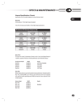
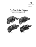
TP-1039
Issued 03-10
Technical Bulletin
Hazard Alert Messages
Read and observe all Warning and Caution hazard alert messages in
this publication. They provide information that can help prevent
serious personal injury, damage to components or both.
WARNING
To prevent serious eye injury, always wear safe eye protection
when you perform vehicle maintenance or service.
Failure to bleed the system whenever any hydraulic system
fitting is loosened or disconnected will allow air to remain in
the system. This will prevent the hydraulic pressure in the
brake system from rising enough to apply the brakes correctly.
This will cause the stopping distance to increase and can
result in serious personal injury.
Never reuse hydraulic brake fluid that has been removed from
a vehicle. Hydraulic brake fluid that has been removed can be
contaminated and can cause damage, loss of braking and
serious personal injury. Always discard hyraulic brake fluid in
accordance with applicable environmental requirements.
Use only the type of hydraulic brake fluid specified by the
equipment manufacturer. Do not use or mix different types of
hydraulic brake fluid. The incorrect hydraulic brake fluid will
damage the rubber parts of the brake caliper and can cause
damage, loss of braking and serious personal injury.
Do not let the brake master cylinder fluid get below the
minimum level during the bleeding operation. Keep the master
cylinder reservoir filled with new DOT-approved brake fluid, as
specified by the original equipment manufacturer. Failure to
keep the brake reservoir level above minimum could result in
more air entering system, making it impossible to effectively
bleed the system.
Meritor WABCO Hydraulic Power
Brake (HPB) System Bleeding
Procedures
Issued
1TP-1039
Technical
03-10
Bulletin
CAUTION
Hydraulic brake fluid is a caustic substance. Contact with
hydraulic brake fluid can cause skin irritation. Do not let
hydraulic brake fluid touch any painted surfaces, as it will
remove the paint. Hydraulic brake fluid may also damage
certain non-metal surfaces. Do not let fluid get on brake pads,
shoes, rotors or disks.
Observe the following when working on the braking system.
CAUTION
Prior to working on the braking system, all bleeder screws and
the master cylinder cap must be cleaned thoroughly;
cleanliness of fluid and areas around the service points have
to be maintained. Do not use mineral oil-based fluid for this
cleaning. Using mineral oil-based fluid can contaminate brake
fluid and could damage the interior of the components and
cause a system malfunction. Cover all electrical connectors
near the bleeder screws carefully to make certain that no
brake fluid enters the terminals or plugs.
NOTE: After removing a component or disconnecting a brake tube
connection, block off ports and brake tubes with appropriate plugs
to prevent the ingress of dirt and unnecessary loss of fluid.
Use only new specified brake fluid from a sealed container to refill
the system. Refer to the specification on the Master Cylinder (MC)
reservoir or in the vehicle service manual.
If a lubricant is required to aid assembly, use only the specified
brake fluid from a sealed container. Do not use any other assembly
lubricant.
During bleeding procedures, brake fluid level must not be allowed to
fall below the MIN mark on the master cylinder reservoir. The master
cylinder reservoir should be regularly checked and filled to the MAX
mark.
Perform the bleeding procedure exactly as described in the
instructions. Perform the reservoir top-off procedure, when bleeding
is complete. Refer to technical publication TP-09121, Filling the
Hydraulic Power Brake (HPB) Master Cylinder Reservoir, for
instructions on filling the master cylinder.
After completing all desired brake service operations, test the
braking system for function and check for leakage.
Use DOT 3 or DOT 4 hydraulic brake fluid. Refer to the vehicle
specification sheet to determine which fluid to use.
How to Obtain Additional Maintenance
and Service Information
Refer to Maintenance Manual MM-0401, Meritor WABCO Hydraulic
Power Brake (HPB) System; and technical publication TP-09121,
Filling the Hydraulic Power Brake (HPB) Master Cylinder Reservoir.
Call ArvinMeritor’s Customer Service Center at 800-535-5560 to
obtain these publications. Meritor WABCO publications are also
available on our website:
While fully depressing the brake pedal, select the Deplete
Accumulators function from the TOOLBOX™ Software
EOL pull-down menu. The pedal must remain fully
depressed during the entire process, until the
TOOLBOX™ Software displays the completion message.
Ensure that the pressure in both accumulators is reading
zero on the diagnostic main screen then release the brake
pedal.
6.
Verify that the brake fluid level in the master cylinder reservoir
is not below MAX level.
NOTE: During bleeding procedures, brake fluid level must not
be allowed to fall below the MIN mark on the master cylinder
reservoir. The master cylinder reservoir should be regularly
checked and filled to the MAX mark with new specified brake
fluid from a sealed container.
Brake Bleeding Procedures
Prepare the pressure bleeder device according to the
instructions provided with the equipment.
NOTE: The pressurized fill and bleed equipment used can be
either “air over fluid” or “fluid over air” type.
8.
Install a suitable adapter from the fill and bleed equipment to
the master cylinder reservoir filler neck. Verify that the adapter
and bleed equipment are securely tightened onto the master
cylinder reservoir filler neck.
9.
Remove the rubber caps from the two relay valve bleeder
screws located on the hydraulic control unit (HCU). Figure 1.
The pressure-assisted brake bleeding procedures may be used with
any fill and bleed equipment capable of filling the system and
creating pressure in the master cylinder reservoir.
Pressure Bleed Procedures
B.
Turn the ignition OFF.
7.
Meritor WABCO does not approve using manual bleeding
procedures.
Fully depress the brake pedal a minimum of 30 times.
The pressure in each brake circuit can be monitored using
the TOOLBOX™ Software. Ensure that the pressure in
each accumulator is at 0 psi.
5.
www.meritorwabco.com
The following brake bleeding methods explain how to bleed the
hydraulic power brake system during installation, or in the event of
air in the brake system.
A.
Figure 1
Master Cylinder Circuit
1.
Park the vehicle on a level surface. Apply the parking brake
and block the wheels to prevent the vehicle from moving.
2.
Turn the ignition OFF and remove the two 30-amp Maxi fuses
for the brake system motors. Refer to the vehicle
manufacturer’s specifications to determine where the fuses are
located.
3.
Connect the diagnostic laptop to the diagnostic connector
located in the cab, under the instrument panel. Set the ignition
key to ON and open the TOOLBOX™ Software program.
4.
Deplete pressure in the accumulators. There are two ways of
depressurizing the system as follows.
TP-1039
Issued 03-10
Page 2
1
1
2
3
4
2
3
4
4008096a
BLEEDER PORT — PRIMARY MASTER CYLINDER CIRCUIT
MASTER CYLINDER INPUT PORT — PRIMARY CIRCUIT
MASTER CYLINDER INPUT PORT — SECONDARY CIRCUIT
BLEEDER PORT — SECONDARY MASTER CYLINDER CIRCUIT
Figure 1
Copyright ArvinMeritor, Inc., 2010
(16579/22882)
Printed in USA
10. Fit the bleeder hose onto one relay valve bleeder screw located
on the hydraulic compact unit.
11. Submerge the free end of the bleeder hose into the partially
filled bleed bottle.
Brake Caliper Circuit
1.
Park the vehicle on a level surface. Apply the parking brake
and block the wheels to prevent the vehicle from moving.
2.
Turn the ignition OFF and remove the two 30-amp Maxi fuses
for the brake system motors. Refer to the vehicle
manufacturer’s specifications to determine where the fuses are
located.
3.
Connect the diagnostic laptop to the diagnostic connector
located in the cab, under the instrument panel. Set the ignition
key to ON and open the TOOLBOX™ Software program.
4.
Deplete pressure in the accumulators. There are two ways of
depressurizing the system as follows.
12. Apply 35 psi (2.4 bar) of pressure from the fill and bleed
equipment to the master cylinder reservoir.
13. Open one of the relay valve bleeder screws until the fluid
begins to flow (about 3/4 turn). Allow the fluid to run until 8.5
ounces (250 cc) has been collected. Take note of the fluid level
in the bottle before starting.
14. When no further air bubbles enter the bleed bottle, close the
bleeder screw. Remove the bleeder hose and tighten the
bleeder screw to 35.4 to 39.8 lb-in (4 to 4.5 Nm). @
NOTE: Verify the fluid level in the master cylinder reservoir.
During bleeding procedures, the brake fluid must not be
allowed to fall below the MIN mark on the master cylinder
reservoir. The master cylinder reservoir should be regularly
checked and filled to the MAX mark.
15. Repeat Steps 13 and 14 with the second bleeder screw.
16. If brake caliper circuit bleeding is required, refer to the
procedure in this section.
17. If brake caliper circuit bleeding is NOT required, install the two
30-amp pump motor fuses.
18. Turn the ignition ON. With 35 psi (2.4 bar) pressure applied to
the master cylinder reservoir, the HCU pump motors will start
up automatically and fill the accumulators. Approximate
running time is 45 seconds. The brake light and buzzer will
turn OFF.
A.
Fully depress the brake pedal a minimum of 30 times.
The pressure in each brake circuit can be monitored using
the TOOLBOX™ Software. Ensure that the pressure in
each accumulator is at 0 psi.
B.
While fully depressing the brake pedal, select the Deplete
Accumulators function from the TOOLBOX™ Software
EOL pull-down menu. The pedal must remain fully
depressed during the entire process, until the
TOOLBOX™ Software displays the completion message.
Ensure that the pressure in both accumulators is reading
zero on the diagnostic main screen then release the brake
pedal.
5.
Turn the ignition OFF.
6.
Verify that the brake fluid level in the master cylinder reservoir
is not below MAX level.
NOTE: During bleeding procedures, brake fluid level must not
be allowed to fall below the MIN mark on the master cylinder
reservoir. The master cylinder reservoir should be regularly
checked and filled to the MAX mark with new specified brake
fluid from a sealed container.
19. Release the pressure from the master cylinder reservoir.
20. Remove the bleed equipment. Fill or drain the master cylinder
reservoir up to the MAX mark with new specified brake fluid
from a sealed container.
21. Install the master cylinder reservoir cap.
7.
Prepare the pressure bleeder device according to the
instructions provided with the equipment.
22. Using the diagnostic laptop and the TOOLBOX™ Software
program, clear all the inactive fault codes.
NOTE: The pressurized fill and bleed equipment used can be
either “air over fluid” or “fluid over air” type.
23. Turn the ignition OFF and disconnect the diagnostic laptop from
the diagnostic connector.
8.
24. Check the system for external leaks.
Install a suitable adapter from the fill and bleed equipment to
the master cylinder reservoir filler neck. Verify that the adapter
and bleed equipment are securely tightened onto the master
cylinder reservoir filler neck.
25. Remove the wheel blocks.
NOTE: If all wheel ends are to be bled, use the following
bleeding order: right rear, left rear, right front, left front.
9.
(16579/22882)
Printed in USA
Fit the bleeder hose onto the caliper bleeder screw at one
wheel end.
Copyright ArvinMeritor, Inc., 2010
TP-1039
Issued 03-10
Page 3
10. Submerge the free end of the bleeder hose into the bleed
bottle.
11. Apply 35 psi (2.4 bar) of pressure from the fill and bleed
equipment to the master cylinder reservoir.
12. Open one caliper bleeder screw until fluid begins to flow (3/4
turn). Allow the fluid to run until 8.5 ounces (250 cc) has been
collected. Take note of the fluid level in the bottle before
starting. Figure 2.
Figure 2
15. If the vehicle is equipped with a power parking brake – SAHR
canister, then bleed the SAHR circuit now using Steps 9-13 of
the Spring-Applied/Hydraulic-Release (SAHR) Parking Brake
Circuit pressure bleed procedure in this section.
16. Install the two 30-amp pump motor fuses.
17. Turn the ignition ON. With 35 psi (2.4 bar) of pressure applied
to the master cylinder reservoir, the HCU pump motors will start
up automatically and fill the accumulators. Approximate
running time is 45 seconds. The brake light and buzzer will
turn OFF.
18. Release the pressure from the master cylinder reservoir.
19. Remove the bleed equipment. Fill or drain the master cylinder
reservoir up to the MAX mark with new specified brake fluid
from a sealed container.
20. Install the master cylinder reservoir cap.
21. Using the diagnostic laptop and the TOOLBOX™ program,
while fully holding the brake pedal depressed, select the
Deplete Accumulators function from the TOOLBOX™ Software
EOL pull-down menu. The pedal must remain fully depressed
during the entire process, until the TOOLBOX™ Software
displays the dialog box that will indicate the completion of the
function. Ensure that the pressure in both accumulators is
reading zero on the diagnostic main screen, then release the
brake pedal.
1004710a
NOTE: The DEPLETE ACCUMULATORS function performs a
cycle of releasing the pressure and charging the pressure back
up in each brake circuit. This cycle helps clear air from the HCU
into the reservoir.
Figure 2
13. If no further air bubbles enter the bleed bottle, close the
bleeder screw. Remove the bleeder hose and tighten the
bleeder screw. Refer to the vehicle manufacturer’s torque
specification for the caliper bleeder screws. For Bosch Pin
Slider calipers, tighten the screws to 106-142 lb-in (12-16
Nm). For Meritor Quadraulic™ disc brake calipers, tighten the
screws to 133 lb-in (15 Nm).
NOTE: Refer to the vehicle manufacturer’s specifications for
specific information about bleeding the calipers. Some calipers
have multiple bleeder screws and require removal of the
wheels and tires to access the bleeder screws. Each bleeder
screw must be bled.
NOTE: Verify the fluid level in the master cylinder reservoir.
During bleeding procedures, the brake fluid must not be
allowed to fall below the MIN mark on the master cylinder
reservoir. The master cylinder reservoir should be regularly
checked and filled to the MAX mark.
14. Repeat Steps 9-13 with the other calipers in the specified
order.
TP-1039
Issued 03-10
Page 4
22. Repeat Step 21 two times.
23. Using the diagnostic laptop and the TOOLBOX™ Software
program, clear all the inactive fault codes.
24. Turn ignition OFF and disconnect the diagnostic laptop from the
diagnostic connector.
25. Check the system for external leaks.
26. Remove wheel blocks.
Spring-Applied/Hydraulic Release (SAHR)
Parking Brake Circuit
Before bleeding the circuit, you must disconnect the parking brake
cable from the spring-applied/hydraulic release (SAHR) canister.
This is to ensure that the SAHR piston achieves the full stroke and
forces most of the fluid volume out of the SAHR canister, thus
moving potential entrapped air into the bleeder screw area.
1.
Park the vehicle on a level surface. Apply the parking brake
and block the wheels to prevent the vehicle from moving.
Copyright ArvinMeritor, Inc., 2010
(16579/22882)
Printed in USA
2.
Turn the ignition OFF and remove the two 30-amp Maxi fuses
for the brake system motors. Refer to the vehicle
manufacturer’s specifications to determine where the fuses are
located.
12. Open the SAHR bleeder screw until fluid begins to flow (3/4
turn). Allow the fluid to run until 8.5 ounces (250 cc) has been
collected. Take note of the fluid level in the bottle before
starting.
3.
Connect the diagnostic laptop to the diagnostic connector
located in the cab, under the instrument panel. Set the ignition
key to ON and open the TOOLBOX™ Software program.
4.
Deplete pressure in the accumulators. There are two ways of
depressurizing the system as follows.
13. If no further air bubbles enter the bleed bottle, close the
bleeder screw. Remove the bleeder hose and tighten the
bleeder screw to specified torque. Refer to the vehicle
manufacturer’s specifications for the correct torque value.
A.
Fully depress the brake pedal a minimum of 30 times.
The pressure in each brake circuit can be monitored using
the TOOLBOX™ Software. Ensure that the pressure in
each accumulator is at 0 psi.
B.
While fully depressing the brake pedal, select the Deplete
Accumulators function from the TOOLBOX™ Software
EOL pull-down menu. The pedal must remain fully
depressed during the entire process, until the
TOOLBOX™ Software displays the completion message.
Ensure that the pressure in both accumulators is reading
zero on the diagnostic main screen then release the brake
pedal.
14. Install the two 30-amp pump motor fuses.
15. Turn the ignition ON. The HCU pump motors will start up
automatically and fill the accumulators. Approximate running
time is 45 seconds. The brake light and buzzer will turn OFF.
16. Release the pressure from the master cylinder reservoir.
17. Remove the bleed equipment. Fill or drain the master cylinder
reservoir up to the MAX mark with new specified brake fluid
from a sealed container.
18. Install the master cylinder reservoir cap.
5.
Turn the ignition OFF.
19. Connect the parking brake cable to the SAHR canister. Refer to
the vehicle manufacturer’s instructions for how to connect and
correctly adjust the parking brake cable. Verify correct
application and release at the parking brake.
6.
Verify that the brake fluid level in the master cylinder reservoir
is not below MAX level.
20. Using the diagnostic laptop and the TOOLBOX™ Software
program, clear all the inactive fault codes.
NOTE: During bleeding procedures, brake fluid level must not
be allowed to fall below the MIN mark on the master cylinder
reservoir. The master cylinder reservoir should be regularly
checked and filled to the MAX mark with new specified brake
fluid from a sealed container.
21. Turn ignition OFF and disconnect the diagnostic laptop from the
diagnostic connector.
Prepare the pressure bleeder device according to the
instructions provided with the equipment.
Changing Hydraulic Brake Fluid
7.
NOTE: The pressurized fill and bleed equipment used can be
either “air over fluid” or “fluid over air” type.
8.
Install a suitable adapter from the fill and bleed equipment to
the master cylinder reservoir filler neck. Verify that the adapter
and bleed equipment are securely tightened onto the master
cylinder reservoir filler neck.
9.
Fit the bleeder hose onto the bleeder screw on the SAHR
chamber.
10. Submerge the free end of the bleeder hose into the bleed
bottle.
11. Apply 35 psi (2.4 bar) of pressure from the fill and bleed
equipment to the master cylinder.
(16579/22882)
Printed in USA
22. Check the system for external leaks.
23. Remove wheel blocks.
1.
Park the vehicle on a level surface. Apply the parking brake
and block the wheels to prevent the vehicle from moving.
2.
Turn the ignition OFF and remove the two 30-amp Maxi fuses
for the brake system motors. Refer to the vehicle
manufacturer’s specifications to determine where the fuses are
located.
3.
Connect the diagnostic laptop to the diagnostic connector
located in the cab, under the instrument panel. Set the ignition
key to ON and open the TOOLBOX™ Software program.
4.
Deplete pressure in the accumulators. There are two ways of
depressurizing the system as follows.
A.
Fully depress the brake pedal a minimum of 30 times.
The pressure in each brake circuit can be monitored using
the TOOLBOX™ Software. Ensure that the pressure in
each accumulator is at 0 psi.
Copyright ArvinMeritor, Inc., 2010
TP-1039
Issued 03-10
Page 5
B.
While fully depressing the brake pedal, select the Deplete
Accumulators function from the TOOLBOX™ Software
EOL pull-down menu. The pedal must remain fully
depressed during the entire process, until the
TOOLBOX™ Software displays the completion message.
Ensure that the pressure in both accumulators is reading
zero on the diagnostic main screen then release the brake
pedal.
16. Fill the master cylinder reservoir up to the MAX mark with new
specified brake fluid from a sealed container. Use DOT 3 or
DOT 4 hydraulic brake fluid. Refer to the vehicle
manufacturer’s specifications to determine which fluid to use.
NOTE: You can speed up the filling process by opening the
bleeder screw of one of the rear calipers. This will allow better
brake fluid flow into the system by expelling the air through the
bleeder screw. Close the bleeder screw when no further air is
exiting the bleeder screw.
5.
Turn the ignition OFF.
6.
Prepare the pressure bleeder device according to the
instructions provided with the equipment.
17. Bleed the master cylinder circuit using the master cylinder
bleeding procedure in this section.
NOTE: The pressurized bleed equipment used for this drain
procedure must be the “air over hydraulic” type.
18. Bleed the rest of the brake system using the brake caliper
circuit bleeding procedure in this section.
7.
Install a suitable adapter from the fill and bleed equipment to
the master cylinder reservoir filler neck. Verify that the adapter
and bleed equipment are securely tightened onto the master
cylinder reservoir filler neck.
8.
Apply 35 psi (2.4 bar) of pressure from the fill and bleed
equipment to the master cylinder.
9.
Fit the bleeder hose onto the caliper bleeder screw at one
wheel end.
10. Submerge the free end of the bleeder hose into the bleed
bottle.
11. Open the bleeder screw until fluid begins to flow (3/4 turn).
Allow the fluid to run until the circuit is completely drained and
no more fluid comes out.
12. Close the bleeder screw.
13. Repeat Steps 8-12 for:
A.
the remaining calipers,
B.
the two relay bleeder screws, and
C.
the SAHR bleeder screw, if equipped
14. Release the pressure from the master cylinder reservoir.
15. Remove the bleed equipment.
Meritor WABCO Vehicle Control Systems
2135 West Maple Road
Troy, MI 48084-7121 USA
800-535-5560
meritorwabco.com
Information contained in this publication was in effect at the time the publication was approved for printing and is subject to
change without notice or liability. Meritor WABCO reserves the right to revise the information presented or to discontinue the
production of parts described at any time.
Copyright 2010
ArvinMeritor, Inc.
All Rights Reserved
Printed in USA
TP-1039
Issued 03-10
(16579/22882)