1
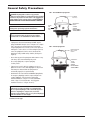
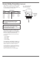
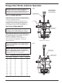
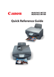
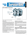
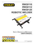
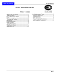
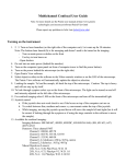
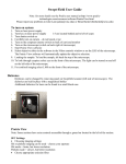
L31171
Rev. 11/05
Sealed Spring Brakes
Life Seal®, Gold Seal® and Midland
Installation Instructions
Contents
GENERAL SAFETY PRECAUTIONS ..................................2-5
SPRING BRAKE DISARMING PROCEDURES ...................20
RECOMMENDED PREVENTATIVE MAINTENANCE ............6
ORANGE ALERT STROKE INDICATOR OPERATION........21
GOLD SEAL/MIDLAND - MECHANICAL RELEASE OF
SPRING BRAKE ...................................................................7-9
DETERMINING WARRANTY STATUS .................................22
LIFE SEAL - MECHANICAL RELEASE OF SPRING
BRAKE....................................................................................10
SEALED INSTALLATION INSTRUCTIONS
COMBINATION SPRING BRAKES ..................................11-15
PIGGYBACK MODEL ......................................................16, 17
ROTATING MOUNTING BOLTS, CLAMPS
AND AIR PORTS....................................................................18
SERVICE DIAPHRAGM REPLACEMENT............................19
Throughout this manual, you will notice the terms “NOTE”, “IMPORTANT”, “WARNING”, and “DANGER” followed by
important product information. So that you may better understand the manual, those terms are defined below. The
warns of the possibility of personal injury or death.
NOTE:
Is used as a reminder of an instruction where the concern deals with product integrity and has to do with installation,
operation, maintenance or service and care of the product.
IMPORTANT:
Used without the safety alert symbol, is used as a reminder of an instruction where the concerns deal with product
integrity and have to do with installation, operation, maintenance or service and care of the product. It is intended
to show that vehicle breakdown and/or expensive repair could result if the instruction is not followed.
WARNING:
Is used with an instruction for the purpose of showing that a safe practice must be adhered to or that an unsafe
practice must be avoided, and that if proper precautions are not taken, personal injury could result.
DANGER:
Indicates a potentially hazardous situation which, if not avoided, may result in serious injury or death.
2
General Safety Precautions
FIG 1 - Gold Seal/Midland Spring Brake
DANGER: A spring brake contains a very powerful
compression spring. Failure to comply with all of the following
instructions may result in forceful release of the piggyback or
spring chamber and its contents which could CAUSE DEATH,
SEVERE PERSONAL INJURY AND/OR PROPERTY DAMAGE.
IMPORTANT: ALWAYS BLOCK WHEELS to prevent vehicle
rollaway when performing any brake maintenance.
TETHERED
DUST PLUG
POCKET
FOR
RELEASE
TOOL
PERMANENTLY
SEALED
CHAMBER
CAUTION:
DO NOT ATTEMPT
TO DISASSEMBLE
DANGER: Haldex DOES NOT recommend the rebuilding of
any of its air brake actuator products. Nor does Haldex
recommend the use of rebuilt Haldex air brake actuators.
• If spring brake shows structural damage DO NOT cage the
spring and DO NOT attempt to service it. Replace the complete
unit. To prevent severe personal injury when removing an
uncaged spring brake from a vehicle, cut the service push rod
making sure to relieve all force on it. After cutting the push rod,
remove the spring brake from the vehicle, then disarm the
spring brake using a suitable safety chamber (See Page 20 Figure 36).
• Never strike any part of the spring brake with a hammer or any
other heavy object; structural damage may result.
• Do not drop spring brake, as power spring may
forcefully release.
• If air pressure is used to aid in the caging process, do not
tighten the release tool more than finger tight. The air pressure
must always be exhausted after the spring has been
mechanically caged prior to any disassembly.
FIG 2 - Life Seal Spring Brake
INTEGRAL RELEASE
TOOL -NO SIDE
POCKET
PERMANENTLY
SEALED
CHAMBER
CAUTION:
DO NOT ATTEMPT
TO DISASSEMBLE
• On all Haldex Life Seal, Gold Seal and Midland Spring Brakes,
the emergency diaphragm cannot be replaced. Replace the
complete piggyback. (Follow instructions listed under
“Mechanical Release” on Page 7-9 for Gold Seal/Midland
brakes. Page 10 for Life Seal brakes. And “Piggyback
Installation Instructions” on Pages 16 and 17).
IMPORTANT: It is recommended that a new service brake
diaphragm be used when installing a new piggyback. DO
NOT use a piloted diaphragm on the service side (a piloted
“protrusion” diaphragm is designed to be used in the
emergency spring chamber only). Use of a piloted diaphragm
results in a reduction of stroke length.
Continued on next page
3
General Safety Precautions
• Haldex manufactures a complete line of 3.0" (76mm) stroke brake
actuators. In some cases these are referred to as “Long Stroke”
(L). In other cases they are referred to as “Extra Long Stroke” (XL).
To avoid confusion, please refer to Table 1 below.
TABLE 1
STROKE MODELS
2.5" (64MM) STROKE MODELS
3.0" (76MM) STROKE MODELS
COMBINATION
PIGGYBACK
COMBINATION
PIGGYBACK
GC2424L
GC2430L
LC2430
GC3030
GC3036
LC3030
GP2424L
GP2430L
LP2430
GP3030
GP3036
LP3030
GC2430XL
LC2430L
GC3030L
LC3030L
GP2430XL
LP2430L
GP3030L
LP3030L
WARNING: NEVER interchange 3.0" (76mm) stroke
actuator components with 2.25" (57mm) or 2.5" (64mm)
stroke components. Performance and stroke may be
seriously affected.
WARNING: NEVER interchange spring brake manufacturers
components. Performance and stroke may be seriously
affected. Although spring brake manufacturers components look
similar, they should never be interchanged.
• When servicing 3.0” stroke actuators, it is imperative that strict
attention is paid to the components. These air brake actuators
have push rod stroke capabilities in excess of the standard 2.25"
(57mm)* or 2.5" (64mm) design. The serviceable components for
these actuators are unique. They include the following:
*2.5” stroke T-24 diaphragm may be used in 2.25” stroke T-24 service
brake applications.
1) Service Diaphragm
2) Service Housing
3) Service Pushrod
4) Complete Piggyback
• These components are uniquely identified as “Long Stroke”, “LS”,
or “3.0" (76mm) Stroke” on each component. The unique square
bosses on the air inlet ports on the aluminum center body easily
identify the spring brake as 3.0" (76mm) stroke (Figure 3).
• To aid in the identification of Long Stroke brakes being used on
vehicles, Haldex has decals available (Figure 3A). These decals
can easily be attached to the side of the vehicle.
Labels can be purchased from your local Haldex Distributor.
4
(Continued)
FIG 3 - Gold Seal & Life Seal 3.0"
(76mm) Stroke Spring Brake
ALUMINUM
CENTER BODY
SQUARE SHAPE
BOSSES ON AIR
PORTS IDENTIFY
BRAKES WITH
3.0" (76 mm)
STROKE
General Safety Precautions
(Continued)
FIG 3A - Long Stroke Brake Alert Decal
L80033
5.50"
3.00"
L80034
5
Recommended Preventative Maintenance
• Preventative maintenance for Haldex Life Seal, Gold Seal and
Midland combination spring brake models is recommended every
three months or every 25,000 miles (40,000 km).
IMPORTANT: ALWAYS BLOCK WHEELS to prevent vehicle
rollaway when performing any brake maintenance.
1. Check the conditions of the foundation brakes, including drums,
shoes and linings, rollers, bushings, etc.
2. Check for structural damage of the Spring Brake, Brake Adjuster
and S-Cam. Replace if necessary.
3a.Gold Seal and Midland Models:
Apply the parking brake. Remove the Dust Plug from the rear of
the chamber and physically inspect the condition of the parking
spring. If the parking spring is broken, replace the Spring Brake
with either a new piggyback unit or an entire unit. Please refer to
Pages 16 and 17 for specific piggyback installation instructions
or to Pages 11 thru 15 for combination installation instructions.
IMPORTANT: ALWAYS replace dust plug after inspection.
3b.Life Seal Models:
Mechanically release the parking brake and follow the
procedure listed on Page 10.
4. Apply the Service Brakes. Check the air lines and fittings for leaks.
Check for proper torque according to Table 4, Page 13.
5. After allowing the brake drum to cool to room temperature, check
for the correct spring brake stroke and verify proper installation.
Proper installation can be verified by following the instructions
listed on Page 15.
6
Gold Seal/Midland - Mechanical Release of Spring Brake
DANGER: Read Pages 2-5 carefully. Do not attempt to
mechanically release (cage) the spring on a spring brake if it
shows structural damage. Caging the spring or disassembly of
the chamber may result in the forceful release of the spring
chamber and its contents which could CAUSE DEATH, SEVERE
PERSONAL INJURY AND/OR PROPERTY DAMAGE. Remove
complete spring brake and replace with new unit.
DANGER: DISARM spring chamber before discarding old
brake. To disarm, use a suitable Safety Chamber (see Page 20).
Failure to disarm assembly prior to disposal may, in time, result
in spontaneous release of the spring chamber and its contents,
which could CAUSE DEATH, SEVERE PERSONAL INJURY AND/OR
PROPERTY DAMAGE.
FIG 4
SERVICE
CLAMP
ASSEMBLY
SIDE POCKET
DUST PLUG
KEY
HOLE
SERVICE
PUSH ROD
TO CAGE PARK BRAKE COMPRESSION SPRING
(RELEASE PARK BRAKE)
SERVICE
HOUSING
RELEASE TOOL
IMPORTANT: ALWAYS BLOCK WHEELS to prevent vehicle
rollaway when performing any brake maintenance.
1. Remove dust plug from release tool key hole in center of spring
chamber (Figure 4).
FIG 5
2. Remove release tool assembly from side pocket of center body
(Figure 4).
RELEASE TOOL
- 1/4 TURN CLOCKWISE
3. Insert release tool through key hole in chamber into the
spring piston (Figure 5 Arrow A).
4. Turn release tool 1/4 turn clockwise (Figure 5 Arrow B).
5. Pull on release tool to ensure stud crosspin is properly
seated in the spring piston.
A
6. Assemble release tool washer and nut on release stud, finger
tighten only (Figure 5).
KEY HOLE
B
RELEASE
TOOL
WASHER
AND NUT
Continued on next page
7
Gold Seal/Midland - Mechanical Release of Spring Brake
(Continued)
DANGER: The below listed instructions only apply when spring
brake is not pressurized. If air pressure is used to compress the
spring, do not tighten release tool more than finger tight. Torquing
the release tool nut while the spring brake is pressurized can cause
spring piston damage resulting in sudden release of the spring
which could CAUSE DEATH, SEVERE PERSONAL INJURY AND/OR
PROPERTY DAMAGE. Air pressure must be released after caging,
prior to any disassembly.
FIG 6
SEE TABLE 2
X
TORQUE TO
35 FT. LBS.
CLOCKWISE
7. a). Turn release tool nut clockwise with hand wrench (DO NOT USE
HIGH SPEED AND/OR POWER DRIVEN IMPACT WRENCH) and
make certain push rod is retracting (Figure 6).
7. b). This procedure will be made much easier if air pressure
(100-120 PSIG; 6.6-8.0 BAR) is used to collapse the
power spring before turning the release tool nut with
a hand wrench. Proper caging will be complete when a slight
resistance is felt after turning the release tool nut. Release the
air pressure after caging prior to any disassembly.
IMPORTANT: Do not over torque release tool assembly. Over
torquing release tool can cause spring piston damage.
IMPORTANT: To insure the power spring is fully caged, the release
tool length (X dimension) (Figure 6) should measure as shown in
Table 2.
TABLE 2
MODEL
1624
2024
2424
2424
2430
2430
2430
3030
3030
3636
3636
3636
STROKE
2 1/4"
2 1/4"
2 1/4"
2 1/2"
2 1/4"
2 1/2"
3"
2 1/2"
3"
2 1/2"
3"
3"
(57mm)
(57mm)
(57mm)
(64mm)
(57mm)
(64mm)
(76mm)
(64mm)
(76mm)
(64mm)
(76mm)
(76mm)
X - MINIMUM
2.9"
2.9"
2.9"
2.9"
2.9"
2.9"
3.4"
2.9"
3.4"
3.6"
2.4"
3.6"
(74mm)
(74mm)
(74mm)
(74mm)
(74mm)
(74mm)
(86mm)
(74mm)
(86mm)
(91mm)
(61mm)
(91mm)
NOTE: If dimension of release tool (X dimension) length is less
than the minimum measurement, then spring brake unit must
be replaced.
Continued on next page
8
RETRACTING
PUSH ROD
HAND
WRENCH
ONLY
Gold Seal/Midland - Mechanical Release of Spring Brake
(Continued)
TO UNCAGE PARK BRAKE COMPRESSION SPRING
(APPLY PARK BRAKE)
FIG 7
TURN RELEASE TOOL NUT
COUNTER CLOCKWISE
1. Turn release stud nut counter clockwise with hand wrench
(DO NOT USE HIGH SPEED OR POWER DRIVEN IMPACT
WRENCH). This procedure will be made much easier if air
pressure (100-120 PSIG; 6.6-8.0 BAR) is used to collapse the
spring (Figure 7).
2. Remove caging tool nut and washer.
3. Push caging tool in, turn 1/4 turn counter clockwise and remove.
HAND
WRENCH
ONLY
4. Place caging tool in pocket with T-head down and washer and
nut up (this allows the washer to protect the pocket from
corrosive elements while allowing the pocket to drain around
the T-head (Figure 8).
5. Torque the nut to 5-8 ft. lb. (6.8-10.8 Nm).
6. Install dust plug in key hole. Insert the plug into the keyhole in
the housing and push firmly until the plug is securely in place.
7. Lift edge of tether plug to be sure the plug is firmly in place.
FIG 8
SERVICE
CLAMP
ASSEMBLY
SEALED TYPE
PIGGYBACK
IMPORTANT: Always re-install tethered dust plug in caging tool
key hole. Failure to do so will result in corrosion and foreign
particle ingestion through the key hole which will void the
warranty. Do not use excessive force when installing the plug.
Excessive force may damage the plug and make it unusable.
Replacement tether plugs can be purchased from your local Haldex
Distributor.
DUST PLUG
KEY
HOLE
SERVICE
PUSH ROD
SERVICE
HOUSING
SIDE POCKET
RELEASE TOOL
9
Life Seal - Mechanical Release of Spring Brake
DANGER: The below listed instructions only apply when
spring brake is not pressurized. If air pressure is used to
compress the spring, do not tighten release tool more than
finger tight. Torquing the release tool nut while the spring brake
is pressurized can cause spring piston damage resulting in sudden release of the spring which could CAUSE DEATH, SEVERE
PERSONAL INJURY AND/OR PROPERTY DAMAGE. Air pressure
must be released after caging, prior to any disassembly.
DANGER: DISARM spring chamber before discarding old
brake. To disarm, use a suitable Safety Chamber (see Page 20).
Failure to disarm assembly prior to disposal may, in time, result
in spontaneous release of the spring chamber and its contents,
which COULD CAUSE DEATH, PERSONAL INJURY AND/OR
PROPERTY DAMAGE.
FIG 11
SEE TABLE 3
X
HAND
WRENCH
ONLY
RETRACTING
PUSH ROD
INTEGRAL CAGING
RELEASE TOOL
TO CAGE PARK BRAKE COMPRESSION SPRING
(RELEASE PARK BRAKE)
IMPORTANT: ALWAYS BLOCK WHEELS to prevent vehicle
rollaway when performing any brake maintenance.
TABLE 3
CHAMBER TYPE
STROKE
X - MINIMUM
X - MAXIMUM
30
30LS
2 1/2" (64mm)
3" (76mm)
2.40" (61mm)
2.90" (74mm)
2.56" (65mm)
3.06" (78mm)
IMPORTANT: Do not over torque release tool assembly. Over
torquing release tool can cause spring piston damage. Life
Seal S-Cam type 55 ft. lb. (74Nm) Maximum, Counter Clockwise.
NOTE: If dimension of release tool (X dimension) length is less than
the minimum measurement, then spring brake unit must be replaced.
1. a). Turn release tool nut counter clockwise with hand wrench (DO
NOT USE HIGH SPEED AND/OR POWER DRIVEN IMPACT
WRENCH) and make certain push rod is retracting (Figure 11).
FIG 12
1. b). This procedure will be made much easier if air pressure
(100-120 PSIG; 6.6-8.0 BAR) is used to collapse the
compression spring before turning the release tool nut with a
hand wrench. Proper caging will be complete when a slight
resistance is felt after turning the release tool nut. Release the
air pressure after caging prior to any disassembly.
TORQUE TO
55 FT. LBS.
(74 Nm) CLOCKWISE
APPLIED
OR
“UNCAGED”
POSITION
RELEASE TOOL NUT
"TORQUE VALUE"
STAMPED ON CHAMBER
IMPORTANT: To ensure the power spring is fully caged, the
release tool length (X dimension) (Figure 11) should
measure as shown in Table 3.
TO UNCAGE PARK BRAKE COMPRESSION
SPRING (APPLY PARK BRAKE)
INJ
MA URY
Y
MIS RE O
HA S U
N
O
R T ICE
IO
V
PR S E R
KE O F D
Y BAN ION
P TAT
O
RT
PA RE
NG FO
S I BE L
2 SA
O
C
DIS AGE
A
SS B R
C EM A
ST LA BL
UD M
R
10
TOR TO
QU RE
L
E
TO E
5
DIS
NO A R M
.1
10 U
DI 37
SP
2. Turn release tool nut until contact is made with the chamber.
Torque to 55 ft. lb. (74 Nm). Torque value is stamped on
chamber (Figure 12).
H
AT M
DE RO
R LT F NG
I
L
D
E
AK S
BR T-LB
E
F
AS -60
0
1. Turn release tool nut clockwise with hand wrench (DO NOT
USE HIGH SPEED OR POWER DRIVEN IMPACT WRENCH).
This procedure will be made much easier if air pressure
(100-120 PSIG; 6.6-8.0 BAR) is used to collapse the spring.
Combination Spring Brake Installation Instructions
INSTALLATION PREPARATION
FIG 13
J
IMPORTANT: Spring brake must be caged prior to performing
installation procedures. If brake is not caged, follow steps on
Pages 7-10 for safety instructions and mechanical release of
spring brake.
NOTE: In an effort to maximize the life of Haldex spring brakes,
Haldex recommends the following brake mounting guidelines when
installing spring brakes on your vehicle(s).
CUT PUSH ROD TO CORRECT INSTALLATION LENGTH
IMPORTANT: Before installing a new combination spring brake,
it is necessary to determine the correct service push rod length
to ensure proper alignment for efficient operation of the spring
brake.
NOTE: Units are furnished with a universal fully threaded push
rod and must be cut to the correct length.
K
FIG 14
PUSH ROD
BRAKE ADJUSTER
IMPORTANT: Place blocks under wheels to prevent vehicle
rollaway before removing spring brake actuators.
NOTE: If spring brake unit being replaced is not available to
take measurements from, follow the procedures listed under
Step 5, Page 12.
1. Remove worn or non-functional spring brake unit from vehicle:
Determine manufacturer and model of unit to be replaced. Refer
to that manufacturer's service manual for caging and removal
instructions.
3/16" (4.8mm)
MAXIMUM PROTRUSION TO
ENSURE NO INTERFERENCE
WITH BRAKE ADJUSTER
2. Make sure the spring chamber of the removed actuator is fully
released (power spring caged) and the service brake push rod is
fully retracted to zero stroke position (i.e. brake fully released).
3. Measure and record the “J” and “K” dimensions from unit to be
replaced (Figure 13).
“J” dimension = The dimension from bottom of actuator to end
of piston rod.
“K” dimension = The dimension from bottom of actuator to
centerline of clevis pin.
4. Take measured J” dimension (Figure 13) from the removed unit
and mark push rod of new unit to be cut.
Continued on next page
11
Combination Spring Brake Installation Instructions
NOTE: Step 5 lists the procedures to determine correct push rod
length when the spring brake being replaced is not available. Move
ahead to Step 6 if correct push rod length is already determined.
FIG 15
5. To determine the correct push rod length of the brake to be
installed, measure the “B” dimension as shown (Figure 15)
and subtract the setup stroke as listed in Table 5 (Page 15).
With the spring brake fully caged: “B” minus Setup
Stroke = Push Rod Length including Clevis. (Figure 16)
CL OF SLACK
ADJUSTER
PARALLEL
TO MOUNTING
SURFACE
MOUNTING SURFACE
CORRECT
NOTE: Setup stroke is only to establish push rod length.
(See Step 6 on Page 14).
WHEN BRAKES ARE
APPLIED
[PARKING OR 60 PSIG
(4 BAR) SERVICE]
EXAMPLE:
For a typical Type 30 spring brake, if “B” (Figure 15) = 5.0 inches,
setup stroke = 1 1/2 inches (Table 5, Page 15). The push rod length
from mounting face to centerline of main clevis pin should measure:
5 minus 1 1/2 = 3 1/2 inches. with the spring brake caged. (Figure 16)
7. Thread clevis jam nut past the mark on push rod. Align
bottom edge of nut with mark to use as a guide for cutting.
Use a sharp hack-saw and cut push rod on the mark.
8. After cutting rod, thread jam nut off to clean up threads.
90°
CL
OF
PUSH
ROD
B
FIG 16
CORRECT
WHEN BRAKES ARE
NOT APPLIED
[PARKING OR 60 PSIG
(4 BAR) SERVICE]
PUSH ROD
LENGTH TO
CENTERLINE
OF CLEVIS PIN
12
90°
APPLIED
BRAKE
6. Before marking push rod to be cut on new unit, be sure the spring
chamber is caged and the push rod is fully retracted to the zero
stroke position. Refer to mechanical release instructions:
Pages 7-9 for Gold Seal brakes. Page 10 for Life Seal brakes.
NOTE: When determining the push rod cut-off length, the length of
the threaded rod protruding between the clevis legs must not exceed
3/16" (4.8mm) to ensure no interference with the operation of the
brake adjuster (Figure 14).
(Cont’d)
CL
OF
PUSH
ROD
B
SET-UP
STROKE
(TABLE 5,
Page 15)
Combination Spring Brake Installation Instructions
MOUNTING SPRING BRAKE TO MOUNTING BRACKET
(Cont’d)
FIG 17
BE CERTAIN THAT
MOUNTING BRACKET
SURFACE IS FREE OF
DEBRIS, BURRS, CRACKS
AND IS FLAT WITHIN
1/64" (.4mm).
When attaching spring brakes to mounting brackets the
following checks and instructions should be performed:
1. Mounting brackets must be inspected to assure that bracket
surface is free from debris, burrs, cracks, weld spatter and is
flat within 1/64" (.4mm) (Figure 17).
TORQUE SPECIFICATIONS
LISTED IN TABLE 4 BELOW.
2. Attach spring brake directly to mounting bracket on axle. Fasten
with mounting hardware (Figure 17). Torque to specifications listed
in Table 4 below.
ALWAYS MOUNT THE BRAKE
CHAMBER DIRECTLY TO THE BRACKET - DO NOT
INSERT SPACERS, WASHERS OR SHIMS BETWEEN
MOUNTING BRACKET AND BRAKE HOUSING.
IMPORTANT: When mounting a spring brake to a horizontal
axle bracket, as shown in Figure 17, the bracket must meet the
minimum contact area (Figure 17A).
When the spring brake mounting bracket requires the studs to be
in the vertical position (rotated 90° from horizontal), the contact
area can be slightly less than the minimum contact area for
horizontal mount.
CAGED SPRING BRAKE.
FIG 17A
6.2" (159mm)
IMPORTANT: Always mount brake chamber directly to bracket, if
a reinforcement plate is necessary, follow the guidelines for plate
attachment below. DO NOT insert spacers, washers or shims
between mounting bracket and brake housing. (Figure 17)
Consult the bracket manufacturer for your application to determine
if a reinforcement plate is necessary.
3.0"
(76mm)
DO NOT mount spring brake in a vertical position. The spring
brake must be mounted within 45 degrees of horizontal
(Figure 18A).
NOTE: In some cases it may be necessary to rotate air ports
and/or clamp bands for proper clearance and installation on
vehicle. (See Page 18 for rotation instructions.)
REINFORCEMENT PLATE
ATTACHMENT GUIDELINES
When attaching a reinforcement plate to the brake mounting bracket
face the following guidelines must be followed:
1.63"
(41.4mm)
BRAKE CHAMBER
MOUNTING BRACKET.
FIG 18
CROSS HATCHED AREA SHOWS MINIMUM
CONTACT SUPPORT AREA REQUIRED FOR
BRAKE CHAMBER MOUNTING.
5/8" (M16) BOLTS,
WASHERS AND NUTS.
1. Attach .25" (6mm) steel plate 7" x 7" (178mm x 178mm) square,
to brake mounting bracket face. Secure with (2) 5/8" or M16 bolts,
washers and nuts, and torque to 50 ft. lb. (67.5 Nm) (Figure 18).
2. Weld reinforcement plate to brake mounting bracket (See Figure 19)
for suggested weldment locations. For exact location and weld size,
refer to axle manufacturer’s guidelines. Allow welds to cool and
remove bolts (Figure 19, Page 14).
3. Attach spring brake directly to new reinforcement plate. Fasten
with mounting hardware (Figure 20, Page 14). Torque to
specifications listed in Table 4 below.
TABLE 4
.25" (6mm) STEEL PLATE
7" X 7" (178mm x 178mm)
(CONTACT AXLE/BRACKET
MANUFACTURER FOR YOUR
APPLICATION).
INSTALLATION TORQUE VALUES
TORQUE
Mounting Hardware
Jam Nut
Port Plug or Reducer
Air Fittings
LIFE SEAL - Release Tool Nut
GOLD SEAL/MIDLAND - Release Tool Nut
GOLD SEAL/MIDLAND - Release Tool Nut
(in side pocket)
Carriage Bolt Nuts (for clamps)
130-150 lb. ft.
15-25 lb. ft.
15-20 lb. ft.
25-30 lb. ft.
55 lb. ft.
25-35 lb. ft.
(177-203 Nm)
(20-34 Nm)
(20-27 Nm)
(34-40 Nm)
(74 Nm)
(34-47 Nm)
5-8 lb. ft. (7-11 Nm)
20-30 lb. ft. (27-40 Nm)
FIG 18A
45°
45°
BRAKE CHAMBER
MOUNTING RANGE
MUST BE WITHIN 45°
OF HORIZONTAL.
Continued on next page
13
Combination Spring Brake Installation Instructions
FIG 19
ATTACH CLEVIS AND AIR LINES
REINFORCEMENT PLATE
WELDMENT LOCATIONS
(CONTACT AXLE/BRACKET
MANUFACTURER FOR
YOUR APPLICATION).
1. Thread jam nut back onto the push rod a sufficient length to
allow assembly of the clevis.
2. Thread clevis onto the push rod. Clevis from removed unit may
be reused provided clevis pin hole is not worn. Adjust clevis to
the same “K” dimension as measured from the removed unit
(Figure 13, Page 11).
3. Hold clevis to prevent it from turning and tighten jam nut against
clevis to torque specifications. (See Table 4, Page 13 for
Installation Torque Values). The clevis must be adjusted so that it
has full thread engagement on the push rod (from flush to 3/16"
(4.8mm) protrusion). (Figure 14, Page 11).
4. Connect the service and emergency air line to the proper air
ports. Torque to specifications listed in Table 4, Page 13.
(Cont’d)
REMOVE BOLTS AFTER
WELDS HAVE COOLED.
BE CERTAIN TO KEEP
WELD AND WELD
SPATTER AWAY FROM
PLATE FACE SURFACE.
TORQUE SPEC LISTED
IN TABLE 4, Page 13.
FIG 20
5. Connect clevis to the slack adjuster using clevis and cotter
pins, and uncage the spring brake. Refer to uncaging
procedures: Pages 7-9 for Gold Seal and Midland brakes. Page
10 for Life Seal brakes.
IMPORTANT: If push rod is not long enough to reach brake
adjuster mounting hole, DO NOT physically pull push rod out
to reach mounting hole.
6. Adjust the brake adjuster to the listed setup stroke (See
Table 5, Page 15). (Figure 22)
CAGED SPRING BRAKE.
Continued on next page
FIG 21
ALWAYS MOUNT THE BRAKE
CHAMBER DIRECTLY TO THE BRACKET - DO NOT
INSERT SPACERS, WASHERS OR SHIMS BETWEEN
MOUNTING BRACKET AND BRAKE HOUSING.
AIR LINES
COTTER PIN
CLEVIS PIN
FIG 23
90° BRAKE ADJUSTER TO
PUSH ROD ANGLE MUST
BE MAINTAINED
CL OF BRAKE
ADJUSTER
PARALLEL
TO MOUNTING
SURFACE
MOUNTING BRACKET SURFACE
CORRECT
WHEN BRAKES ARE
APPLIED
[PARKING OR
60 PSIG (4 BAR) SERVICE]
CAGED SPRING BRAKE.
FIG 22
90°
90° max.
CORRECT
CL
OF
PUSH
ROD
WHEN BRAKES ARE
NOT APPLIED
[PARKING BRAKE CAGED
AND 0 PSIG (0 BAR)
SERVICE]
CAGED SPRING BRAKE
14
CL
OF
PUSH
ROD
SET-UP
STROKE
(TABLE 5)
Combination Spring Brake Installation Instructions
VERIFY PROPER INSTALLATION
FIG 24
1. With the brake applied, the following conditions must occur:
a.) push rod 90° to the centerline of slack adjuster; b.) push
rod 90° to the mounting face of the spring brake. (Figure 23,
Page 14).
TABLE 5
CHAMBER
TYPE
MORE
OR
LESS
THAN
INCORRECT
9
12
16
16
20
20
20**
1-3/4"
1-3/4"
2-1/4"
2-1/2"
2-1/4"
2-1/2"
3"
(44mm)
(44mm)
(57mm)
(64mm)
(57mm)
(64mm)
(76mm)
24
24
24**
30
30**
36
2-1/4"
2-1/2"
3"
2-1/2"
3"
3"
(57mm)
(64mm)
(76mm)
(64mm)
(76mm)
(76mm)
RECOMMENDED CHAMBER
STROKE RANGE
MINIMUM
MAXIMUM
1-3/8"
1-3/8"
1-3/4"
2"
(Should be as 1-3/4"
short a stroke
2"
as possible 2-1/2"
without brake 1-3/4"
dragging)
2"
2-1/2"
2"
2-1/2"
2-1/4"
SET-UP STROKE
APPLIED BRAKE*‡
(35mm)
(35mm)
(44mm)
(51mm)
(44mm)
(51mm)
(64mm)
1"
1"
1-3/8"
1-1/2"
1-3/8"
1-1/2"
1-3/4"
(25mm)
(25mm)
(35mm)
(38mm)
(35mm)
(38mm)
(44mm)
(44mm)
(51mm)
(54mm)
(51mm)
(64mm)
(57mm)
1-3/8"
1-1/2"
1-3/4"
1-1/2"
1-3/4"
1-3/4"
(35mm)
(38mm)
(44mm)
(38mm)
(44mm)
(44mm)
* Stroke length measured by applying parking brake or 60 PSIG (4 Bar) service brake application
** Long Stroke
‡ Typical setup stroke values
NOTICE: For special applications consult vehicle, brake or brake adjuster manufacturers.
IMPORTANT: Incorrect push rod brake adjuster setup will result
in improper brake operation.
90°
WHEN BRAKES ARE
APPLIED
[PARKING OR 60 PSI
(4 BAR) SERVICE]
STROKE VALUES
AVAILABLE
STROKE
(Cont’d)
CL
MORE
THAN
OF
PUSH
ROD
90°
FIG 25
MOUNTING
SURFACE
INCORRECT
WHEN BRAKES ARE
APPLIED
[PARKING OR 60 PSI
(4 BAR) SERVICE]
MORE
OR
LESS
THAN
90°
CL
OF
PUSH
ROD
LESS
THAN
90°
2. If the setup results in the condition depicted in Figure 24
or Figure 25, the spring brake is misaligned and must be
corrected by one or more of the following:
Figure 24 a.) shorten push rod, b.) align spring brake on
mounting bracket, c.) mount clevis in proper brake adjuster hole.
Figure 25 a.) lengthen push rod, b.) align spring brake on mounting
bracket, c.) mount clevis in proper brake adjuster hole.
If misalignment cannot be corrected, consult with foundation brake
manufacturer for verification of correct mounting bracket position.
3. Once the spring brake and push rod are set properly
(Figure 23, Page 14), release the brakes and follow vehicle
manufacturer’s instructions for brake adjustment.
IMPORTANT: After installation, check for proper emergency
operation, service operation and brake adjustment.
15
Piggyback Installation Instructions
TO REMOVE PIGGYBACK FROM SERVICE HOUSING
FIG 28a
ONE PIECE
SERVICE CLAMP
ASSEMBLY
1. Refer to mechanical release instructions: Pages 7-9 for
Gold Seal/Midland brakes. Page 10 for Life Seal brakes.
WARNING: Failure to comply with all instructions for
mechanical release may result in the forceful release of
the spring which COULD CAUSE DEATH, SEVERE PERSONAL
INJURY AND/OR PROPERTY DAMAGE.
VISE GRIP
PLIERS
2. If vehicle air pressure was used to aid in the caging process,
exhaust the air pressure.
3. To prevent sudden release of service housing assembly and to
facilitate rotation of air ports or mounting studs, the service push
rod should be prevented from retracting by clamping the service
push rod in place with vise grip pliers as shown (Figure 28a/b).
4. Disconnect the airlines from the air ports on the center body.
SERVICE
PUSH ROD
CAGED
SPRING
CHAMBER
5. Remove service clamp assembly (Figure 28a/b).
FIG 28b
IMPORTANT: DO NOT bend the clamp assembly when removing.
TO INSTALL PIGGYBACK ON SERVICE HOUSING
TWO-PIECE
SERVICE CLAMP
ASSEMBLY
1. If piggyback is not caged, follow steps on Pages 7-9 for Gold
Seal/Midland brakes. Page 10 for Life Seal brakes.
WARNING: Failure to comply with all instructions for
mechanical release may result in the forceful release of
the spring which could CAUSE DEATH, SEVERE PERSONAL
INJURY AND/OR PROPERTY DAMAGE.
2. Before installing piggyback on existing non-pressure housing,
inspect the clamp assembly, the service return spring, the
service push rod and non-pressure housing. If any structural
damage is noted, replace with new parts.
3. Wipe the surface of the service push rod clean of any oil, grease
or dirt. Check to see that the bottom most vent holes in the
housing are not plugged.
IMPORTANT: It is recommended that a new service brake
diaphragm be used when installing a new piggyback. DO NOT
use a piloted diaphragm on the service side (a piloted
“protrusion” diaphragm is designed to be used in the emergency
spring chamber only). Use of a piloted diaphragm results in a
reduction of stroke length.
FIG 29
VISE GRIP
PLIERS
SERVICE
CLAMP
ASSEMBLY
CAGED
SPRING
CHAMBER
4. Place the new service diaphragm in center body (as shown) and
center the housing over the diaphragm and adapter lip
(Figure 29).
5. Ensure that diaphragm is properly seated between the center body
and housing lip and that the air ports are in the desired positions.
When reinstalling the one-piece service clamp assembly (Figure
28a), torque the carriage nut to specifications listed in Table 4,
Page 13. When reinstalling the two-piece service clamp assembly
(Figure 28b), tighten each nut equally, alternating every other turn.
Torque each carriage nut to specifications listed in Table 4, Page 13.
DO NOT strike clamp or unit with a hammer.
Continued on next page
16
SERVICE
HOUSING
EMERGENCY
AIR PORT
SERVICE
DIAPHRAGM
CENTER
BODY
SERVICE
AIR PORT
Piggyback Installation Instructions
(Continued)
6. Check carriage bolts and clamp assembly for proper seating
around the center body and housing lip, and remove vise grip
pliers previously clamped around the service push rod to prevent it
from retracting.
7. Reconnect the air lines to the air ports on the center body, making
sure to connect the proper lines to the service and emergency
ports (Figure 29). Torque to specifications listed in Table 4, Page
13.
8. Apply a maximum of 120 PSIG (8 BAR) air to the service port and
check diaphragm seal for leakage by applying a water and soap
solution to the service clamp area. (No leakage allowed).
9. Uncage park brake power spring. Refer to uncaging instructions:
Pages 7-9 for Gold Seal/Midland brakes. Page 10 for
Life Seal brakes.
IMPORTANT: After reassembly, check for proper emergency
and service brake operation. For brake adjustment, follow
vehicle manufacturer’s instructions.
17
Rotating Mounting Bolts, Clamps and/or Air Inlet Ports
TO ROTATE SERVICE HOUSING MOUNTING STUDS
FIG 32a
1. For Mechanical Release of Spring Brake see Pages 7-9 for Gold
Seal/Midland brakes. Page 10 for Life Seal brakes.
DANGER: Failure to comply with all instructions for
mechanical release may result in the forceful release of the
spring which could CAUSE DEATH, SEVERE PERSONAL
INJURY AND/OR PROPERTY DAMAGE.
ONE PIECE
SERVICE CLAMP
ASSEMBLY
VISE GRIP
PLIERS
2. If vehicle air pressure was used to aid in the caging process,
exhaust the air pressure.
3. To prevent sudden release of service housing assembly and to
facilitate rotation of air ports or mounting studs, the service push
rod should be prevented from retracting by clamping the service
push rod in place with vise grip pliers as shown (Figure 32a/b).
SERVICE
PUSH ROD
4. Remove service clamp/carriage bolt and rotate service housing
(Figure 32a/b) or center body (Figure 33) to desired position.
5. Ensure that diaphragm is properly seated between the center body
and housing lip and that the air ports are in the desired positions.
When reinstalling the one-piece service clamp assembly (Figure
32a), torque the carriage nut to specifications listed in Table 4,
Page 13. When reinstalling the two-piece service clamp assembly
(Figure 32b), tighten each nut equally, alternating every other turn.
Torque each carriage nut to specifications listed in Table 4, Page
13. DO NOT strike clamp or unit with a hammer.
CAGED
SPRING
CHAMBER
SERVICE
HOUSING
FIG 32b
TWO-PIECE
SERVICE CLAMP
ASSEMBLY
6. Check carriage bolts and clamp assembly for proper seating
around the center body and housing lip, and remove vise grip
pliers previously clamped around the service push rod to prevent it
from retracting.
7. Apply a maximum of 120 PSIG (8 BAR) air pressure to the
service port and check seal for leakage by applying a water and
soap solution to the service clamp area (No leakage is allowed).
8. Uncage park brake power spring. Refer to uncaging instructions:
Pages 7-9 for Gold Seal/Midland brakes. Page 10 for Life Seal
brakes.
FIG 33
SERVICE CLAMP
ASSEMBLY
CAGED
SPRING
CHAMBER
WARNING: After reassembly, check for proper emergency and
service brake operation. For brake adjustment, follow vehicle
manufacturer’s instructions.
SERVICE
HOUSING
18
CENTER
BODY
Service Diaphragm Replacement
1. For Mechanical Release of Spring Brake see Pages 7-9 for Gold
Seal/Midland brakes. Page 10 for Life Seal brakes.
DANGER: Failure to comply with all instructions for
mechanical release may result in the forceful release of
the spring which could CAUSE DEATH, SEVERE PERSONAL
INJURY AND/OR PROPERTY DAMAGE.
FIG 34a
ONE PIECE
SERVICE CLAMP
ASSEMBLY
VISE GRIP
PLIERS
2. If vehicle air pressure was used to aid in the caging process,
exhaust the air pressure.
3. To prevent sudden release of the piggyback or service push rod
assembly and to facilitate the installation of the new diaphragm,
the service push rod should be prevented from retracting by
clamping the service push rod in place with vise grip pliers as
shown (Figure 34a/b).
SERVICE
PUSH ROD
4. Remove service clamp assembly and discard old diaphragm.
5. Inspect the service clamp assembly, the center body wall and lip,
the housing, the service return spring and service push rod. If any
structural damage is noted, replace with new part.
CAGED
SPRING
BRAKE
6. Wipe the surface push rod plate clean of any oil, grease
or dirt.
FIG 34b
7. Place the new service diaphragm in center body and center the
housing over the diaphragm and center body (Figure 35).
TWO-PIECE
SERVICE CLAMP
ASSEMBLY
IMPORTANT: It is recommended that a new service brake
diaphragm be used when installing a new piggyback. DO NOT
use a piloted diaphragm on the service side (a piloted
“protrusion” diaphragm is designed to be used in the
emergency spring chamber only). Use of a piloted diaphragm
results in a reduction of stroke length.
8. Ensure that diaphragm is properly seated between the center body
and housing lip and that the air ports are in the desired positions.
When reinstalling the one-piece service clamp assembly (Figure
34a), torque the carriage nut to specifications listed in Table 4,
Page 13. When reinstalling the two-piece service clamp assembly
(Figure 34b), tighten each nut equally, alternating every other turn.
Torque each carriage nut to specifications listed in Table 4, Page
13. DO NOT strike clamp or unit with a hammer.
9. Check carriage bolts and clamp assembly for proper seating
around the center body and housing lip, and remove vise grip
pliers previously clamped around the service push rod to prevent it
from retracting.
FIG 35
CAGED
SPRING
BRAKE
10. Apply a maximum of 120 PSIG (8 BAR) air pressure to the
service port and check diaphragm seal for leakage by applying
a water and soap solution to the service clamp area (No
leakage is allowed).
11. Uncage power spring (See instructions on Pages 7-9 for Gold
Seal/Midland brakes. Page 10 for Life Seal brakes.).
IMPORTANT: After reassembly, check for proper emergency
and service brake operation. If installed on vehicle, check brake
adjustment by following vehicle manufacturer’s instructions.
SERVICE
DIAPHRAGM
(FLAT SURFACE
WITH NO
PROTRUSIONS)
CENTER BODY
19
Disarming Procedures: Piggyback and Combination Service/Spring Brakes
FIG 36
DANGER: A Piggyback or Combination Service/Spring Brake
must be disarmed before disposal, or forceful release of the
power spring may occur in the future without warning.
NOTE: A detailed drawing of the Safety Chamber is available free
of charge upon request. Contact Haldex Engineering Department at
800-643-2374. (Drawing #110372 also on the web in
Resources/Technical Litertaure)
1. Remove the caged Piggyback or Combination Service/Spring Brake
from vehicle, after removal uncage the parking brake power spring.
2. Open the lid of the Safety Chamber and place the uncaged
Piggyback or Combination Service/Spring Brake inside the chamber,
close lid and lock hinges in place with bolts as shown (Figure 36).
NOTE: Service push rod may need to be cut in order to fit a
Combination Service/Spring Brake into the Safety Chamber
(Figure 36).
SAFETY
CHAMBER
3. While wearing safety glasses, use an acetylene cutting torch and
cut a 3" (76mm) diameter hole (Figure 37) out of the Spring Brake
chamber wall through one of the openings in the Safety Chamber
(Figure 36).
4. Once the power spring is exposed, use the acetylene cutting torch to
cut the exposed spring in one or more places until the power spring
pieces can be moved around inside the Spring Brake chamber with
a long screwdriver or similar tool through the disarming chamber
openings.
SAFETY CHAMBER OPENINGS
FIG 37
5. Once the power spring pieces can be moved around inside the
Spring Brake chamber, the disarming process is complete and the
piggyback can be removed from the Safety Chamber after it has
cooled down. The unit can be submersed in water to cool it quickly.
WARNING: Cutting of the Spring Brake Chamber with an
acetylene torch can result in harmful fumes. Do not breathe
these fumes. All cutting should be done outside or in a well
ventilated area. After cutting the chamber, submerse it in water
to cool. If the disarmed unit is not cooled, it will emit additional
fumes and it could start a fire if stored near combustible
material.
20
UNIT UNCAGED
CUT 3" (76mm) DIAMETER HOLE HERE
Orange Alert Stroke Indicator Operation
IMPORTANT: All Haldex brake chambers are equipped with a
stroke indicator which meets October 1994 FMVSS-121
requirements. Please read the following information carefully
and familiarize yourself with the operation of this feature.
FIG 38
NOTE: LIFE SEAL VIEWS
SHOWN TO REPRESENT
SEALED BRAKE MODELS.
THREADED PORTION
OF SERVICE PUSH ROD
WHAT IS A STROKE INDICATOR?
A Haldex Orange Alert stroke indicator is an orange knurled band
located on the service push rod. This band is permanently embossed
on the push rod and painted (Figure 38).
The orange band (stroke indicator) is normally inside the brake
chamber (Figure 38) and will only start to protrude outside of the
mounting face of the service housing when the spring brake or
service chamber has only 20% of stroke remaining (Figure 39).
PUSH ROD DISC
HOW TO USE A STROKE INDICATOR
STROKE INDICATOR
(ORANGE BAND)
IMPORTANT: A stroke indicator is not intended to be used as the
only indicator of when to adjust the brakes on a vehicle. For
brake adjustment, follow vehicle manufacturer’s instructions.
At the point where the leading edge of the stroke indicator is level
with the mounting face of the service housing, as shown (Figure 39),
the combination spring brake or service chamber has only 20% of
available stroke remaining. (See Table 6 below).
When the stroke indicator becomes visible, maintenance is
required. The brake may need adjustment, or it may require
component replacement.
SPRING BRAKE FULLY RETRACTED
IMPORTANT: Depending on the location and type of mounting
bracket used, it may be difficult to observe the stroke indicator’s
protrusion once the spring brake or service chamber has been
mounted to the vehicle.
IMPORTANT: When disassembly of the Haldex Spring Brake is
required, consult the Haldex “Instructions for Mechanical
Release and Diaphragm Replacement.” (See Pages 7-9 for Gold
Seal/Midland brakes. Page 10 for Life Seal brakes.)
TABLE 6
TYPE
RECOMMENDED BRAKE RE-ADJUSTMENT STROKE
RATED STROKE
RE-ADJUST STROKE
(SIZE)
INCHES
MILLIMETERS
INCHES
MILLIMETERS
9
12
16
16
20
20
20
24
24
24
30
30
36
1.75
1.75
2.25
2.50
2.25
2.50
3.00
2.25
2.50
3.00
2.50
3.00
3.00
44
44
57
64
57
64
76
57
64
76
64
76
76
1.38
1.38
1.75
2.00
1.75
2.00
2.50
1.75
2.00
2.50
2.00
2.50
2.25
35
35
44
51
44
51
64
44
51
64
51
64
57
FIG 39
LEADING EDGE OF
STROKE INDICATOR
MOUNTING FACE OF
SERVICE HOUSING
21
Determining Warranty Status
Actuator Date Code Change
For standardization and consistency, Haldex is modifying the date code format on all
brake actuators produced after November 1, 2004. The date code will remain in the
same location on all actuators.
The new date codes can be interpreted using the following information:
Day of Year
DDD
Days running of the year
Shift
S
A = First Shift
B = Second Shift
C = Third Shift
Year
YY
Two Digit Year
Location
L
A = Apodaca
(Monterrey), Mexico
K = Iola, Kansas
For example, a date code of 307A04A would translate to Tuesday, November 2, 2004,
First Shift, Apodaca (Monterrey), Mexico.
Date codes on actuators built in Apodaca (Monterrey), Mexico (formerly Anchorlok)
between June 1, 1990 and October 31, 2004, can be interpreted using the following
information.
Market
O
O = OEM
D = Distributor
Day of Year
DDD
Days running of the year
Year
YY
Two Digit Year
Run No.
XX
Production run
Date codes on actuators built in Iola, Kansas (formerly Midland) prior to November 1,
2004 can be interpreted using the following information.
Day of Year
DDD
Days running of the year
Shift
S
A = First Shift
B = Second Shift
C = Third Shift
Year
Y
Single Digit Year
Location
L
K = Iola, Kansas
If you have questions about this date code change or other Haldex Actuator technical
issues, please contact your local Haldex Sales Professional.
22
Notes:
23
Commercial Vehicle Systems
North American Sales Division
Haldex Brake Products Corporation
10707 N.W. Airworld Drive
Kansas City, MO 64153-1215
Phone: (816) 891-2470
Fax: (816) 801-4198
North American Sales Division
Haldex Limited
525 Southgate Drive, Unit 1
Guelph, Ontario CANADA N1G 3W6
Phone: (519) 826-7723
Fax: (519) 826-9497
www.haldex.com · www.hbsna.com
Rev. 11/05 250 ART L31171
[Replaces 951 20 001 Rev. B - June 2002]