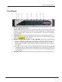
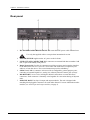
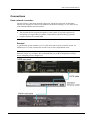
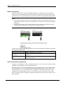
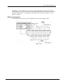
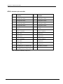
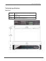
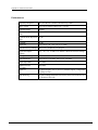
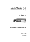
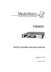
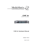
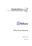
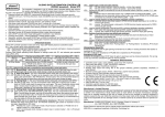
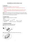
1
CAB 4n Dante Hardware Manual Version 1.6.6.0 January 25, 2013 Copyright notice The information contained in this manual is subject to change without notice. Peavey Electronics is not liable for improper installation or configuration. The information contained herein is intended only as an aid to qualified personnel in the design, installation and maintenance of engineered audio systems. The installing contractor or end user is ultimately responsible for the successful implementation of these systems. All creative content in this manual, including the layout, art design, content, photography, drawings, specifications and all other intellectual property is Copyright © 2013 Peavey Electronics Corporation. All Rights Reserved. Features & specifications subject to change without notice. Prepared by Peavey Digital Research, 6 Elm Place, Eynsham, Oxford, OX29 4BD, UK. Email:[email protected]. Scope This guide describes how to physically install a CAB 4n Dante and configure it with basic settings. It is assumed that you have installed NWare and are familiar with how to use it effectively. For information on NWare, refer to the NWare User Guide. ii Version 1.6.6.0 January 25, 2013 Contents Chapter 1 Before you start .....................................................................................1 Important network considerations ............................................................................................................2 Thank You! ...............................................................................................................................................2 Warranty Registration ...............................................................................................................................2 What's in the box? ....................................................................................................................................2 Chapter 2 Introduction to CAB 4n .........................................................................3 Description ................................................................................................................................................4 Features....................................................................................................................................................4 Applications ..............................................................................................................................................4 Audio input and output modules ...............................................................................................................5 Using a CAB 4n with a NION....................................................................................................................6 Front Panel ...............................................................................................................................................7 Rear panel ................................................................................................................................................8 Chapter 3 Installing the CAB 4n ............................................................................9 Introduction .............................................................................................................................................10 What you will need .................................................................................................................................10 Connections ............................................................................................................................................11 What to do next ......................................................................................................................................14 Appendix A Reference Information ....................................................................15 GPIO overview .......................................................................................................................................16 Technical specifications ..........................................................................................................................19 Gain structure .........................................................................................................................................22 Technical Support ...................................................................................................................................22 Warranty statement ................................................................................................. 23 January 25, 2013 Version 1.6.6.0 iii Chapter 1 Before you start In This Chapter Important network considerations ..................................................................... 2 Thank You! ....................................................................................................... 2 Warranty Registration ....................................................................................... 2 What's in the box? ............................................................................................. 2 January 25, 2013 Version 1.6.6.0 1 Chapter 1 - Before you start . Important network considerations This product is designed to operate on a network backbone or infrastructure. The design, implementation and maintenance of this infrastructure is critical to correct operation and performance of the product. Peavey Electronics Corp does not support nor service network cabling, hubs, switches, patch bays, wall plates, connector panels or any other type of network interconnect device. Please ensure that these components and their associated installation techniques have been properly designed and installed for audio and network applications. Thank You! Thank you for purchasing this MediaMatrix product. It is designed to provide years of trouble-free operation and high quality performance. We are confident that you will find this product and other MediaMatrix products to be of the highest quality. Warranty Registration Please take a few minutes and fill out the warranty registration card. Although your warranty is valid without the registration, the information you provide with the form is crucial to our support group. It enables us to provide better service and customer support, and to keep you informed of new product updates. Tip: Refer to the warranty statement at the rear of this manual for details of what your warranty includes and what the limitations are. What's in the box? The CAB 4n is packaged in a single container. This container includes the following items: CAB 4n IEC removable power supply line cord (120VAC Domestic, 230VAC Export) 19 Three-screw Euro connectors * User Manual/Literature Package MM Series i/o cards * (as ordered). * These items are shipped pre-installed. If any of these items are missing, please contact your Authorized Peavey MediaMatrix contractor/dealer. 2 Version 1.6.6.0 January 25, 2013 Chapter 2 Introduction to CAB 4n In This Chapter Description ........................................................................................................ 4 Features ............................................................................................................. 4 Applications ...................................................................................................... 4 Audio input and output modules ....................................................................... 5 Using a CAB 4n with a NION .......................................................................... 6 Front Panel ........................................................................................................ 7 Rear panel ......................................................................................................... 8 January 25, 2013 Version 1.6.6.0 3 Chapter 2 - Introduction to CAB 4n . Description The CAB 4n is a professional digital audio processor intended for fixed installation applications. This 2U rack-mount package is designed to provide high quality audio performance and easy to use controls. Engineered from the ground up with the commercial sound systems contractor in mind, the CAB 4n includes removable screw connectors for easy installation and cost effective servicing, as well as front panel hidden ID assignment. Features Scalable I/O Architecture Supports all MediaMatrix 4-channel I/O cards 8x8, 16x0, 0x16, 12x4 or 4x12 I/O configurations Supports short-loading RS-485 connection for serial bridging Integrated Dante serial bridging Configurable GPIO Optional DIN rail package for external control terminations Fan cooled 2U package with new NION cosmetics Front panel audio metering Front panel network status and fault indicators Word clock sync option supports MediaMatrix Buddy Link Universal power supply. Applications 4 Stadiums Auditoriums Arenas Civic centers Performing arts centers Theaters Courts of law Houses of worship Campus buildings Theme parks Hotel meeting rooms Conference centers Schools Version 1.6.6.0 Cruise ships Teleconferencing Distance learning Large-scale paging Multi-purpose facilities Retail Restaurants & bars Gaming Institutional paging Communications Correctional facilities Professional complexes Residential. January 25, 2013 CAB 4n Dante Hardware Manual Audio input and output modules The CAB 4n supports a number of different input and output modules. These modules are factory fitted into the four-channel bays at the rear of the unit. Note: A CAB 4n may be ordered short loaded, that is, with some of the bays empty. In this case, blanking panels will be fitted. MM-Line 4 Four line level inputs Software controllable analog gain and input sensitivity Can be mixed with MM-Mic 4 (four line / four mic) Colored black Up to four of these cards can be installed. Slot bays A, B, C or D can be used. MM-Mic 4 Four mic or line level inputs Software controllable phantom power and gain for each channel Studio grade microphone preamplifiers Colored green Up to four of these cards can be installed. Slot bays A, B, C or D can be used. MM-AEC 4 (Discontinued) Four mic level inputs with acoustic echo cancellation and noise reduction Software controllable phantom power and gain for each channel Studio grade microphone preamplifiers User-selectable coarse gain control AEC level adjustable presets Removable, balanced Euro input connectors Colored orange Up to three of these cards can be installed. Slot bays A, B or C can be used. Note: A signal from either output 1 or output 2 of an output card is required as an echo cancellation reference. The output card must be installed next to the MM-AEC 4 card(s). All of the MM-AEC 4 cards can receive their reference signals from the same output card. MM-OUT 4 January 25, 2013 Four line level outputs Software controllable output sensitivity and gain for each channel Colored blue Up to four of these cards can be installed. Slot bays A, B, C or D can be used. Version 1.6.6.0 5 Chapter 2 - Introduction to CAB 4n Using a CAB 4n with a NION The CAB 4n is designed to work in conjunction with a NION. In the example below, a project is created in NWare, then deployed to a NION, so it can control the CAB 4ns on the network. Note: There is no fixed limit on the number of CABs that a NION can control, but adding more CABs will consume more system resources on the NION. 6 Version 1.6.6.0 January 25, 2013 CAB 4n Dante Hardware Manual . Front Panel 1. HARDWARE ID SWITCHES Four rotary switches for setting the hardware ID. Located behind tamperproof panel. 2. FAULT LED Indicates an unexpected condition within the network interface. Some fault conditions will also light the RX Error and/or TX Error LEDs; this is to indicate whether the unexpected condition is in the receive or transmit processes. The errors are reported by a series of flashes. 3. LINK LED Indicates the physical layer connection has been established between the CAB 4n and the network switch. The status of the connection is also indicated by the Link LED in the block in NWare. 4. HARDWARE ID INDICATORS or AUDIO METERS. These LEDs are dual-purpose: a) Before a valid network connection is in place, they indicate the hardware ID. They are used in conjunction with the hardware ID switches (see item #1 above) to set the Hardware ID, which allows NWare and the NIONs to communicate with, and control, the CAB 4n. b) Once the CAB 4n is being controlled by the NION software, they become peak reading LED ladder displays, indicating audio input/output levels. For inputs, the signal level is displayed after the A/D converters. For outputs, the signal level is displayed after the D/A converters. 5. POWER LED Indicates that the CAB 4n is powered from an AC mains power source. January 25, 2013 Version 1.6.6.0 7 Chapter 2 - Introduction to CAB 4n . Rear panel 1. IEC POWER CABLE RECEPTACLE The removable IEC power cable connects here. Use only the supplied cable or an equivalent international version. 2. POWER SWITCH Applies mains AC power to the CAB 4n. 3. LINK OUT & IN CONNECTOR BNC connectors to transmit link data to another CAB unit, as part of the Buddy Link process. 4. Dante Network I/O Two RJ-45 connectors providing a primary and secondary interface to the Dante network via a CAT5e or CAT6 cable. One connection is required to pass audio to or from the device. The second connection provides redundancy. 5. GPIO Female DB-25 connector socket used for 8 configurable, general purpose ports, consisting of external Digital I/O, Analog I/O or Rotary Encoder control, plus 4 relays. 6. RS-485 PORT Two two-wire, half-duplex RS-485 connections on removable Euro connectors. Each connector is internally wired together for convenient busing of adjacent units. 7. MODULE BAYS Four bays for input and output modules. The unit is shipped with matching black pluggable connectors for each audio channel. For more information on the modules, see Audio input and output modules (on page 5). 8 Version 1.6.6.0 January 25, 2013 Chapter 3 Installing the CAB 4n In This Chapter Introduction ....................................................................................................... 10 What you will need ........................................................................................... 10 Connections....................................................................................................... 11 What to do next ................................................................................................. 14 January 25, 2013 Version 1.6.6.0 9 Chapter 3 - Installing the CAB 4n . Introduction The CAB 4n is designed to mount in a standard EIA electronic equipment rack. Because the CAB 4n includes forced air cooling, rack mounted vent panels are not required for most installations. However, vent panels may be required in large installations where multiple units are mounted in a single rack. It is generally accepted that a ratio of 2:1 usually provides adequate performance. In installations where adverse conditions exist, and room temperatures are likely to rise, additional vents should be installed. This product should be installed so that its mounting position does not interfere with proper ventilation. Do not block air intake or exhaust vents. When dressing off wiring harnesses, take care with CAT 5/5e/6 cables. Do not tie-wrap bundles of cables too tightly. Leave plenty of room for bends, allowing the cable to progress naturally from the RJ-45 connector. Creating tightly wrapped CAT 5/5e/6 wire bundles can cause data transmission errors. It is possible for line level audio and data signals to contaminate microphone level signals. We therefore recommend that the cabling for the different signal types is separated. What you will need A MediaMatrix NION with Dante interface. The latest Dante Controller software. (Updates can be downloaded from the Audinate website.) The latest NWare software. (Updates can be downloaded from the MediaMatrix website (http://mm.peavey.com/downloads/index.cfm).) A computer running Microsoft Windows, with monitor, mouse and keyboard. At least 1 CAB 4n with associated MM™ I/O 4 ch cards loaded. An assortment of CAT 5e or CAT 6 cables. An audio source, cables, power amplifier and loudspeaker. A small Phillips screwdriver. A small flat-blade screwdriver. A T15 Torx screwdriver. A network switch connected to the Dante network. Note: Dante uses standard Voice over IP (VoIP) Quality of Service (QoS) switch features to prioritize clock sync and audio traffic over other network traffic. QoS is available in many inexpensive and enterprise Ethernet switches. Any switch that supports Diffserv (DSCP) QoS with strict priority and 4 queues, and has Gigabit ports for inter-switch connections should be appropriate for use with Dante, but we recommend that you check the Q&A section on the Audinate website (http://www.audinate.com) for details of any other requirements. In MediaMatrix, the minimum Dante network consists of a single NION, a CAB 4n audio bridge loaded with appropriate MM™ I/O 4 ch cards and a single Ethernet switch. Many systems will include more NIONs and CAB devices, but this is the most basic configuration. 10 Version 1.6.6.0 January 25, 2013 CAB 4n Dante Hardware Manual Connections Dante network connection The first priority is the Dante network connection. The RJ-45 connectors on the Dante interface are designed to connect with standard, off-the-shelf Category 5e or 6 cable for use with standard Ethernet network switches. Notes: The network must be properly designed for each system. If you lack experience in networking, we suggest that you partner with someone with networking experience. Gigabit switches are recommended. Example A typical Dante system includes a CAT 6 cable from each CAB to a network switch. An additional CAT 6 cable connects the switch to one or more NION Dante cards. Note: The example below is the most basic configuration. Large systems on managed networks can get very complex. We recommend that you get this configuration working before attempting a more complex one. January 25, 2013 Version 1.6.6.0 11 Chapter 3 - Installing the CAB 4n Audio connections Each audio connection on the CAB and NION products is a single, three-wire, balanced analog circuit. The connections are identical for both microphone, line input and line output connections. We recommend that audio connections are made with high quality shielded wire. Notes: As with any electronic connection, care should be taken to ensure that the termination is solid. There should be no stray wire strands, kinks or nicks in the wire jacket for a proper termination. Stranded wires should not be soldered. Solder will cold flow under the pressure of the screw terminal, causing a loose connection to develop over time. If you want to connect an unbalanced audio source to the CAB or NION, make the connections as shown in the table below. Unbalanced input cable CAB or NION input connector Positive (+) Positive (+) GND GND and negative (-) CAT 5e and CAT 6 connections Category 5e and category 6 cables (commonly known as CAT 5e and CAT 6) are two wiring standards recommended for use with Dante networks. Both cable types use a UTP (Unshielded Twisted Pair) configuration. CAT 5e cables typically use 24–26 AWG wire. CAT 6 cable tends to have slightly more copper in each cable, with standard gauges of 22–24 AWG. The cable is coupled to in-line RJ-45 connectors. As the conductor sizes are generally the same, CAT 6 jacks may also be used with CAT 5e cable. Special crimping tools are required to make the termination; these are widely available, as are the connectors. 12 Version 1.6.6.0 January 25, 2013 CAB 4n Dante Hardware Manual Note: A ratcheting type crimping tool is highly recommended. The use of non-ratcheting crimping tools, while occasionally adequate, typically results in considerably higher failure rates for field terminated connections. There are stranded and solid varieties of CAT 5e and CAT 6 cable. The stranded form is more flexible and withstands more bending without breaking and is suited for reliable connections with insulation piercing connectors, but makes less reliable connections in insulation-displacement connectors (IDCs). The solid form is less expensive and makes reliable connections into insulation displacement connectors, but makes less reliable connections in insulation piercing connectors. When used for 10/100/1000BASE-T, the maximum allowed length of a CAT 5e or CAT 6 cable is 100 meters or 328 feet. This consists of 90 meters (300 ft) of solid horizontal cabling between the patch panel and the wall jack, plus 10 meters (33 ft) of stranded patch cable between each jack and the attached device. Since stranded cable has higher attenuation than solid cable, exceeding 10 metres of patch cabling will reduce the permissible length of horizontal cable. Different types of connectors are used with either type of wire. There is a bent tine connector intended for use with solid core wire, and an aligned tine connector for use with stranded cable. The bent tine connector will generally work on stranded wire, but not the other way around. All cable types must be properly installed and terminated to meet specifications. The cable must not be kinked or bent too tightly (the bend radius should be at least four times the outer diameter of the cable). The wire pairs must not be untwisted and the outer jacket must not be stripped back more than 1/2 inch (1.27 cm). There are two main standards for termination: T568A and T568B. For more information on the wiring for these standards, see Wikipedia (http://en.wikipedia.org/wiki/T568A#T568A_and_T568B_termination). Notes: A single CAT 5e or CAT6 cable run must not exceed 100 meters. Make sure your connector matches your cable type. If you are not sure, use the bent tine variety. When terminating CAT 5e or CAT6 cable, it is important that the natural twist of each pair is carried through as close as possible to the point of termination at the connector. We recommend that you familiarize yourself with the wiring color schemes so they are second nature to you. An error in the cabling of an Ethernet network is often the primary cause of system errors. It is very important that you build the cable with all pairs properly terminated. This will prevent any confusion later, and give your cable a solid mechanical connection. The use of pre-made and pre-tested cabling can greatly simplify and expedite installation for wiring within a rack. There are two main standards for termination: T568A and T568B. It is important that both ends of a cable are terminated in line with one of these standards and you do not use one standard for one end of the cable and the other for the other end. The cable will not function normally. January 25, 2013 Version 1.6.6.0 13 Chapter 3 - Installing the CAB 4n What to do next The CAB 4n is managed and configured using NWare. Refer to the section Adding a CAB 4n to your design in the NWare User Guide to see how to use a CAB 4n in your audio system design. 14 Version 1.6.6.0 January 25, 2013 Appendix A Reference Information In This Appendix GPIO overview ................................................................................................. 16 Technical specifications .................................................................................... 19 Gain structure .................................................................................................... 22 Technical Support ............................................................................................. 22 January 25, 2013 Version 1.6.6.0 15 Appendix A - Reference Information . GPIO overview NION and CAB products include a versatile GPIO (General Purpose Input Output) system at the rear for terminating external logic, controls, relays and other external systems. Each control pin is supported by NWare for configuration, control and monitoring. Any combination of control pins may be used simultaneously, regardless of the configuration. Caution: The pin assignments for the GPIO ports on the NION and CAB devices are not the same. Please be sure to check the documentation carefully when connecting devices to the ports. Configurable general purpose ports (8 control pins) These ports represent the bulk of the GPIO functionality. Each of these ports can be configured as follows: Digital Output 3.0V TTL logic - Low: 0VDC - 0.4VDC; High: 2.4VDC - 3.3VDC Digital Input 3.0V TTL logic - Low: 0VDC - 0.8VDC; High: 2.0VDC - 24VDC Analog Input Using external, regulated 24VDC supply. Rotary encoder Requires 2 pins and a common. NC and NO relays (4 sets) Four Form C relays are available for general purpose usage. These are user configurable from within NWare. Fault relay A hardware fault indicator that shows that the CAB is working correctly, or that an internal fault has occurred. Connection A 25-pin DSub connector (DB-25) is used for accessing the GPIO functions. Although you can terminate GPIO functions directly to the DB-25 connector, we recommend that you use the optional breakout accessory (GPIO-25: Peavey Part# 00510490). 16 Version 1.6.6.0 January 25, 2013 CAB 4n Dante Hardware Manual The GPIO-25 is a convenient way to access each pin and facilitates easy rack wiring and troubleshooting. The GPIO-25 is a DIN rail package and includes removable Euro connectors for terminating the pins. A single DB-25 male/female cable connects the GPIO-25 to the NION or CAB 4n. GPIO pin assignment The illustration below shows the pin assignments for the CAB 4n GPIO system. January 25, 2013 Version 1.6.6.0 17 Appendix A - Reference Information . GPIO connector pin-out table Pin Function Pin Function 1 Configurable GPIO 14 Configurable GPIO 2 Configurable GPIO 15 Configurable GPIO 3 Configurable GPIO 16 Configurable GPIO 4 Configurable GPIO 17 Configurable GPIO 5 Ground 18 Ground 6 Relay 1 Common 19 Relay 3 Common 7 Relay 1 N.C. 20 Relay 3 N.C. 8 Relay 1 N.O. 21 Relay 3 N.O. 9 Relay 2 Common 22 Relay 4 Common 10 Relay 2 N.C. 23 Relay 4 N.C. 11 Relay 2 N.O. 24 Relay 4 N.O. 12 Fault Relay N.C. (1=Power off) 25 Fault Relay Common 13 Fault Relay N.O. (1=Power on) State 1 indicates continuity with pin 25. 18 Version 1.6.6.0 January 25, 2013 CAB 4n Dante Hardware Manual . Technical specifications Mechanical Dimensions (H x W x D) 19" W x 12-7/8" D x 3-1/2" H (48.26 x 29.71 x 8.78 cm) Weight 9.5 lbs. (4.3 kg) Mounting Double EIA Space Rack Mount (2U) January 25, 2013 Version 1.6.6.0 19 Appendix A - Reference Information . Performance Frequency Response +0 / -0.3 dB, 20 ~ 20 kHz, referenced @ 1 kHz THD + Noise Line Level: 0.006%, Mic Level: < 0.01% Dynamic Range 106 dB Equivalent Input Noise (EIN) Mic Level: < -126 dBu Common Mode Rejection 55 dB Ratio Crosstalk 90 dB Full-Scale Line Level: +30, +24, +18, or +12 dBu Input Sensitivity Settings Mic Level: -42 dBu at +63 dB gain 20 Full-Scale Output Settings +24, +18, +12, +6 dBu, Less than 0.5 dB error between settings Analog Gain Range Line Level: -95.5 dB to +30.5 dB, Mic Level: 0 to 63 dB Input Impedance Line Level: 9.5 k Ohms, Mic Level: 4 k Ohms Output Impedance 102 Ohms Minimum Load Impedance 600 Ohms Audio I/O 16 inputs/outputs, line or mic level modular inputs, configurable in groups of four. LED Metering 16 peak-reading headroom LED meters Zero LED indicates level <1 dB below full-scale Version 1.6.6.0 January 25, 2013 CAB 4n Dante Hardware Manual . General A/D, D/A Quantization 24 bit Audio Transmission Quantization 24 bit Sample Rate (Fs) 48 kHz Master Clock Speed (256 Fs) 24.476 MHz Digital Audio Channels per unit 16 inputs/outputs at 24-bit Digital Audio Interface Dante: 100 or 1000 BaseT Ethernet, uses standard 8-conductor RJ-45 jack RS-485 3-conductor half-duplex, 1 port with 2 multi-drop connections Word-Clock Ports 2 BNC I/O ports, 1 port with 2 multidrop connections AC Power Range 100 ~ 240 VAC, 47 to 63 Hz Universal Power Supply AC Line Current 450 mA (rms) Power Consumption 32 W Power Dissipation 108 BTU (27 kcal) Finish Gray powder coat, painted steel and brushed aluminum face plate Agency Compliance Listings (as of press time): UL, CUL, CE, and FCC part 15, Class A January 25, 2013 Version 1.6.6.0 21 Appendix A - Reference Information . Gain structure It is important to understand the basics of gain structure and how it relates specifically to the CAB. In most cases, the CAB is shipped from the factory with unity gain through the unit. In other words, if you introduce a 1.23VAC 1 kHz sine wave into the input channel of a CAB without adjusting any controls, you will get the same 1.23VAC sine wave on an output channel (when the signal paths are directly connected and without audio processing). However, we recommend that unity gain settings are checked before testing the unit. The CAB is primarily intended for larger MediaMatrix systems, where a different gain structure set up may be required. Adjusting the gain structure for the CAB is possible both at the analog and digital gain stages. All controls for adjusting the input and output gain stages can be found on the control surface of each CAB device. Technical Support When you require assistance with your product, you can get help from several sources. Apart from the online Knowledge Center, there are many technical documents, white papers and application notes on our website and on other websites on the Internet, covering subjects including Python programming, SNMP and serial control. If you cannot find the information you require, contact your dealer or distributor. If you are still unable to solve the issue, you can contact us directly using the details below. MediaMatrix has an extensive Technical Services Group that provides technical support, repair and implementation services. Peavey Electronics Corp., MediaMatrix Division, 5022 Hartley Peavey Drive, Meridian, MS 39305, USA. Phone: 601.483.9548 Phone (toll free): 866.662.8750 Fax: 601.486.1678 Website: http://mm.peavey.com (http://mm.peavey.com). 22 Version 1.6.6.0 January 25, 2013 Warranty statement MediaMatrix® PEAVEY ELECTRONICS CORPORATION DOMESTIC (USA) LIMITED WARRANTY Effective Date: May 1, 2005 What Peavey Will Do We will repair or replace (at Peavey's discretion) products covered by warranty at no charge for labor or materials. If the product or component must be shipped to Peavey for warranty service, the consumer must pay initial shipping costs. If the repairs are covered by warranty, Peavey will pay the return shipping costs. What This Warranty Covers How To Get Warranty Service This Warranty covers defects in material and workmanship in Peavey MediaMatrix products purchased and serviced in the United States of America (USA). End Users: Take the defective product and your dated sales receipt or other proof of purchase to your Authorized MediaMatrix Systems Integrator or Authorized Peavey Service Center. System Integrators: Ship the defective product, prepaid, to Peavey Electronics Corporation, International Service Center, 412 Highway 11 & 80 East, Meridian, MS 39301, 601-483-5365. Include a detailed description of the problem, the name and location of the jobsite and a copy of your invoice as evidence of warranty coverage. Please include a complete return shipping address. What This Warranty Does Not Cover The Warranty does not cover: (1) damage caused by accident, misuse, abuse, improper installation or operation, rental, product modification or neglect; (2) damage occurring during shipment; (3) damage caused by repair or service performed by persons not authorized by Peavey; (4) products on which the serial number has been altered, defaced or removed; (5) products not purchased from an Authorized MediaMatrix Integrator. This warranty does not cover associated costs incurred from servicing equipment, including, but not limited to, travel, jobsite-related costs, fabrication, freight, loaner equipment, installation, cabling or harnessing, mounting materials or other variable costs. Limitation of Implied Warranties ANY IMPLIED WARRANTIES, INCLUDING WARRANTIES OF MERCHANTABILITY AND FITNESS FOR A PARTICULAR PURPOSE, ARE LIMITED IN DURATION TO THE LENGTH OF THIS WARRANTY. Some states do not allow limitations on how long an implied warranty lasts, so the above limitation may not apply to you. Who This Warranty Protects In applications where the product is sold over the counter, this Warranty protects the original retail purchaser. In applications where the product is part of an integrated system, and such system is warrantied by the integrator as a complete assembly, this Warranty protects only the system integrator. How Long This Warranty Lasts The Warranty begins on the date of purchase by the original retail purchaser or on the date received by the system integrator. (See Who This Warranty Protects, above). The duration of the Warranty varies by product as summarized below. 5 Years MediaMatrix® DPU cards, NION™ Processing Nodes, CABs, I/O cards, Cinema Processors Power Amplifiers, Pre-Amplifiers, Mixers, Electronic Filter Sets and Dynamics Processors. 1 Year MM Series Cardframes, MF Series Cardframes, ControlMatrix™ Host Processors, Servers and Controllers, nControl, nTouch 180, nTouch 60, xControl LCDs, nWall Exclusions of Damages PEAVEY'S LIABILITY FOR ANY DEFECTIVE PRODUCT IS LIMITED TO THE REPAIR OR REPLACEMENT OF THE PRODUCT, AT PEAVEY'S OPTION. IF WE ELECT TO REPLACE THE PRODUCT, THE REPLACEMENT MAY BE A RECONDITIONED UNIT. PEAVEY SHALL NOT BE LIABLE FOR DAMAGES BASED ON INCONVENIENCE, LOSS OF USE, LOST PROFITS, LOST SAVINGS, DAMAGE TO ANY OTHER EQUIPMENT OR OTHER ITEMS AT THE SITE OF USE, OR ANY OTHER DAMAGES WHETHER INCIDENTAL, CONSEQUENTIAL OR OTHERWISE, EVEN IF PEAVEY HAS BEEN ADVISED OF THE POSSIBILITY OF SUCH DAMAGES. Some states do not allow the exclusion or limitation of incidental or consequential damages, so the above limitation or exclusion may not apply to you. This Warranty gives you specific legal rights, and you may also have other rights which vary from state to state. If you have any questions about this warranty or service received, or if you need assistance in locating an Authorized Service Center, please contact the Peavey International Service Center at (601) 483-5365. Features and specifications subject to change without notice. Remote Control Panels, Plates, Paging Stations, Ambient Sense Devices and other devices installed in user-accessible locations. 90 Days Loudspeaker Components (including speakers, baskets, drivers, diaphragm replacement kits and passive filter networks.) and all Accessory Products January 25, 2013 Version 1.6.6.0 23 W ord Back P age MediaMatrix® A Division of Peavey Electronics Corp. 5022 Hartley Peavey Drive, Meridian Mississippi, 39305, USA Phone: 866.662.8750 http://mediamatrix.peavey.com Features & Specifications subject to change without notice Copyright © 2013, All Rights Reserved 03601640