1
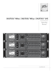
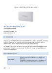
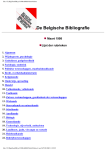
D Series Hardware Manual Version 1.7.2.0 March 27, 2015 Copyright notice The information contained in this manual is subject to change without notice. Peavey Electronics is not liable for improper installation or configuration. The information contained herein is intended only as an aid to qualified personnel in the design, installation and maintenance of engineered audio systems. The installing contractor or end user is ultimately responsible for the successful implementation of these systems. All creative content in this manual, including the layout, art design, content, photography, drawings, specifications and all other intellectual property is Copyright © 2015 Peavey Electronics Corporation. All Rights Reserved. Features & specifications subject to change without notice. All other registered trademarks or trademarks are the property of their respective owners. The ratc-server component is based in part on the work of the libwebsockets project: http://libwebsockets.org. Prepared by Peavey Digital Research, 6 Elm Place, Eynsham, Oxford, OX29 4BD, UK. Email:[email protected] (mailto:[email protected]). Scope This guide describes how to install a D1V or D4S device and how to connect the device to a NION or Digitool MX. ii Version 1.7.2.0 March 27, 2015 Contents Chapter 1 Important safety instructions................................................................ 1 Safety warnings ........................................................................................................................................2 Chapter 2 Before you start ..................................................................................... 5 Warranty Registration ...............................................................................................................................6 Important network considerations ............................................................................................................6 What you will need ...................................................................................................................................6 What's in the box? ....................................................................................................................................6 Thank You! ...............................................................................................................................................6 Chapter 3 Introduction to the D series .................................................................. 7 Description ................................................................................................................................................8 Features....................................................................................................................................................8 Applications ..............................................................................................................................................9 D1V front and rear panel ..........................................................................................................................9 D4S front and rear panel ........................................................................................................................10 Chapter 4 Installing and configuring the D series ............................................. 13 Introduction .............................................................................................................................................14 Connecting up a D series panel .............................................................................................................15 Setting the device ID for a panel ............................................................................................................17 Setting end of line (EOL) terminations ...................................................................................................21 Specifying switch or trigger mode for buttons (D4S only) ......................................................................22 Warranty statement .................................................................................................25 March 27, 2015 Version 1.7.2.0 iii Chapter 1 Important safety instructions In This Chapter Safety warnings................................................................................................. 2 March 27, 2015 Version 1.7.2.0 1 Chapter 1 - Important safety instructions . Safety warnings Warning: When using electrical products, basic cautions should always be followed, including the following: 1. 2. 3. 4. 5. 6. 7. 8. 9. 10. 11. 12. 13. 14. 15. 16. 17. 18. 2 Read these instructions. Keep these instructions. Heed all warnings. Follow all instructions. Do not use this apparatus near water. Clean only with a dry cloth. Do not block any of the ventilation openings. Install in accordance with manufacturer’s instructions. Do not install near any heat sources such as radiators, heat registers, stoves or other apparatus (including amplifiers) that produce heat. Do not defeat the safety purpose of the polarized or grounding-type plug. A polarized plug has two blades with one wider than the other. A grounding type plug has two blades and a third grounding plug. The wide blade or third prong is provided for your safety. If the provided plug does not fit into your outlet, consult an electrician for replacement of the obsolete outlet. Protect the power cord from being walked on or pinched, particularly at plugs, convenience receptacles, and the point they exit from the apparatus. Only use attachments/accessories provided by the manufacturer. Use only with a cart, stand, tripod, bracket, or table specified by the manufacturer, or sold with the apparatus. When a cart is used, use caution when moving the cart/apparatus combination to avoid injury from tip-over. Unplug this apparatus during lightning storms or when unused for long periods of time. Refer all servicing to qualified service personnel. Servicing is required when the apparatus has been damaged in any way, such as power-supply cord or plug is damaged, liquid has been spilled or objects have fallen into the apparatus, the apparatus has been exposed to rain or moisture, does not operate normally, or has been dropped. Never break off the ground pin. Write for our free booklet Shock Hazard and Grounding. Connect only to a power supply of the type marked on the unit adjacent to the power supply cord. If this product is to be mounted in an equipment rack, rear support should be provided. Control panel devices, including the xControl range, D series and nTouch 60, are designed for mounting in NEMA metal enclosures. Grounding to the front plate is required. Note for UK only: If the colors of the wires in the mains lead of this unit do not correspond with the terminals in your plug‚ proceed as follows: a) The wire that is colored green and yellow must be connected to the terminal that is marked by the letter E‚ the earth symbol‚ b) colored green or colored green and yellow. c) The wire that is colored blue must be connected to the terminal that is marked with the letter N or the color black. Version 1.7.2.0 March 27, 2015 D Series Hardware Manual d) The wire that is colored brown must be connected to the terminal that is marked with the letter L or the color red. 19. This electrical apparatus should not be exposed to dripping or splashing and care should be taken not to place objects containing liquids, such as vases, upon the apparatus. 20. The on/off switch in this unit does not break both sides of the primary mains. Hazardous energy can be present inside the chassis when the on/off switch is in the off position. The mains plug or appliance coupler is used as the disconnect device, the disconnect device shall remain readily operable. 21. Exposure to extremely high noise levels may cause a permanent hearing loss. Individuals vary considerably in susceptibility to noise-induced hearing loss, but nearly everyone will lose some hearing if exposed to sufficiently intense noise for a sufficient time. The U.S. Government’s Occupational Safety and Health Administration (OSHA) has specified the following permissible noise level exposures: Duration Per Day in Hours Sound Level dBA, Slow Response 8 90 6 92 4 95 3 97 2 100 1½ 102 1 105 ½ 110 ¼ or less 115 According to OSHA, any exposure in excess of the above permissible limits could result in some hearing loss. Ear plugs or protectors to the ear canals or over the ears must be worn when operating this amplification system in order to prevent a permanent hearing loss, if exposure is in excess of the limits as set forth above. To ensure against potentially dangerous exposure to high sound pressure levels, it is recommended that all persons exposed to equipment capable of producing high sound pressure levels such as this amplification system be protected by hearing protectors while this unit is in operation. SAVE THESE INSTRUCTIONS! March 27, 2015 Version 1.7.2.0 3 Chapter 2 Before you start In This Chapter Warranty Registration ....................................................................................... 6 Important network considerations ..................................................................... 6 What you will need ........................................................................................... 6 What's in the box? ............................................................................................. 6 Thank You! ....................................................................................................... 6 March 27, 2015 Version 1.7.2.0 5 Chapter 2 - Before you start . Warranty Registration Please take a few minutes and fill out the warranty registration card. Although your warranty is valid without the registration, the information you provide with the form is crucial to our support group. It enables us to provide better service and customer support, and to keep you informed of new product updates. Tip: Refer to the warranty statement at the rear of this manual for details of what your warranty includes and what the limitations are. Important network considerations This product uses a proprietary protocol on an RS-485 multi-drop network. It should not be connected to other networks. The devices on this RS-485 network should be connected in a single daisy chain string. Star network connections are not recommended. Each device has two RJ-45, loop through connectors, to facilitate proper network configuration. Each D series device draws approximately 16mA. If you are using a NION, the RS-485 network will support a maximum of 32 devices. However, if you are using a Digitool MX16, MX32 or LIVE, a maximum of 15 devices may be used. What you will need Phillips head screwdriver to fit 6-32 mounting screws. What's in the box? In the box you will find: D4S or D1V flush-mount panel Black Phillips head countersunk 6-32 mounting screws (2) User manual (this manual). If any of these items is missing, please contact your Authorized Peavey contractor/dealer. Thank You! Thank you for purchasing this Peavey product. It is designed to provide years of trouble-free operation and high quality performance. We are confident that you will find this product and other Peavey products to be of the highest quality. 6 Version 1.7.2.0 March 27, 2015 Chapter 3 Introduction to the D series In This Chapter Description ........................................................................................................ 8 Features ............................................................................................................. 8 Applications ...................................................................................................... 9 D1V front and rear panel .................................................................................. 9 D4S front and rear panel ................................................................................... 10 March 27, 2015 Version 1.7.2.0 7 Chapter 3 - Introduction to the D series . Description The D series comprises two individual control units. D4S D1V This is a one-gang Decora panel with four programmable buttons and status LEDs. This is a one-gang Decora panel with four programmable virtual rotary controls and status LEDs. Features 8 Standard Decora package Assignable controls LED control status indicators Label space for customization RS-485 network connectivity Easy wiring & installation Flexible Addressable Tracking rotary control locations Software upgradeable Integral EOL Terminators Low power requirements Power supplied via RS-485 connection Cost effective. Version 1.7.2.0 March 27, 2015 D Series Hardware Manual Applications Conference Rooms Meeting Rooms Combinable Ballrooms Paging Systems Entertainment Systems Theater BOH (Back of House) Bars & Restaurants Schools Medical Facilities Institutional Facilities Municipal Facilities Courtrooms Lecture Halls Presentation Rooms. D1V front and rear panel 1. Device selection LED Single-color green LED illuminates to indicate which of the four devices wired to the NWare D1V device is active. 2. Knob position LED Single-color green LED array indicates current position of rotary knob. 3. Label Space Use this area to fix a label identifying the selection that has been made. For example, the knob could switch between audio sources for background music: CD player 1 and 2. March 27, 2015 Version 1.7.2.0 9 Chapter 3 - Introduction to the D series 4. Knob Rotary encoder with integral push-switch. Turning the knob adjusts the level of the wired control. The level is indicated by lit LEDs around the knob. Pushing the knob selects a device wired to the NWare D series device. Note: If the LEDs start flashing, this means no NWare D series device in the NWare project has been assigned the device ID set on the physical device. 5. Mounting Bracket Single-gang (1G) mounting bracket for installation into standard NEMA 1G switch box. 6. DIP Switch Eight-position DIP switch assigns button mode, device ID and EOL termination function. 7. RJ-45 Connectors Dual RJ-45 connectors for installation into D Series RS-485 network. These connectors are wired in parallel and include data and power supply connections. The recommended cable is UTP Category 5 (CAT5) or better. D4S front and rear panel 1. Label Space Use this area to fix a label identifying the selection that has been made. For example, the knob could switch between audio sources for background music: CD player 1 and 2. 2. Device selection LED Single-color green LED illuminates to indicate which of the four devices wired to the NWare D1V device is active. 3. Device selection switch Momentary push button. Pushing the switch selects a device wired to the NWare D series device. The button operating mode (switch or trigger mode) is controlled by DIP switches. Switch mode 10 In switch mode, each button is independent and does not function as part of a mutually exclusive group. Each button sends alternate on and off commands with each button press. The LED indicates the on/off status for each button separately. This feature is used primarily to turn Version 1.7.2.0 March 27, 2015 D Series Hardware Manual on specific audio functions, such as a mute, or in conjunction with level controls, switches and simple audio routing. Trigger mode In trigger mode, each button transmits a momentary signal when pressed. This signal is a one-shot command that the software recognizes as a trigger. A trigger has no on or off state, it is simply a momentary logic signal. When a trigger has been activated, the button LED will illuminate and stay illuminated until another trigger in the same group is activated. The buttons work in the same way as radio buttons in a software application, and are typically used as source selectors. Note: If the LEDs start flashing, this means no NWare D series device in the NWare project has been assigned the device ID set on the physical device. 4. Mounting Bracket Single-gang (1G) mounting bracket for installation into standard NEMA 1G switch box. 5. DIP Switch Eight-position DIP switch assigns button mode, device ID and EOL termination function. 6. RJ-45 Connectors Dual RJ-45 connectors for installation into D Series RS-485 network. These connectors are wired in parallel and include data and power supply connections. The recommended cable is UTP Category 5 (CAT5) or better. March 27, 2015 Version 1.7.2.0 11 Chapter 4 Installing and configuring the D series In This Chapter Introduction ....................................................................................................... 14 Connecting up a D series panel ......................................................................... 15 Setting the device ID for a panel....................................................................... 17 Setting end of line (EOL) terminations ............................................................. 21 Specifying switch or trigger mode for buttons (D4S only) ............................... 22 March 27, 2015 Version 1.7.2.0 13 Chapter 4 - Installing and configuring the D series . Introduction D Series panels are designed to mount in standard NEMA electrical enclosures. This includes boxes designed for fixed installation into sheet rock, wood or masonry construction. All cabling and terminations should be installed into conduit, securely coupled to the mounting box and system ground plane. Note: NEMA encloses are not shipped with D series panels. They must be bought separately. For a proper finish, use only Decora style cover plates to match the box gang size. 14 Version 1.7.2.0 March 27, 2015 D Series Hardware Manual Connecting up a D series panel D series control panels require a separate wiring infrastructure that includes RS-485 data and low voltage power in a bus or daisy chain topology. For best performance and reliability, only Category 5 (CAT5) cable or better should be used for D Series networks. Cable runs exceeding 2000 feet are possible using CAT5 cable, proper conduit and terminations. In some cases, especially when extremely long cable runs are present, it may be necessary to terminate the end of the data line (EOL). In adverse conditions, both ends of the data line may require EOL termination. If this is the case, you can terminate the far end of the network by enabling an additional EOL termination at the last panel in the chain using the DIP switch (see End of line (EOL) terminations (on page 21)). The diagram below shows a typical set up using a NION and two D series panels. Power is supplied via the NION RS-485/422 port. A maximum of 31 D series units can be daisy chained to the NION in this type of configuration. March 27, 2015 Version 1.7.2.0 15 Chapter 4 - Installing and configuring the D series The diagram below shows a typical set up using a Digitool MX32 and two D series panels. Power is supplied via the Digitool RS-485 serial port. Without an external power source, a maximum of 15 D series units can be daisy chained to the Digitool in this type of configuration. With a power source available, the maximum increases to 31. D Series cable pin outs When using a Digitool MX, the cable is fitted with a CAT5 (T568B) connector at both ends. However, when the NION is used, a serial D connector is used at the NION end, with a CAT5 (T568B) connector at the other end. For both the NION and Digitool, units that are daisy chained to the first D series unit use a cable with a CAT5 connector at both ends. 16 Version 1.7.2.0 March 27, 2015 D Series Hardware Manual CAT5 (T568B) plug NION RS-485 port Description 1 1 485 + 2 2 485 - 4 4 Power 5 5 Power ground Setting the device ID for a panel In a D series control system, each panel must be assigned a device ID. This allows NWare to identify each physical control on the device when the user interacts with it. For the D4S, the physical controls are buttons. For the D1V, there is a single rotary control with a push button. There are 32 device IDs available per NWare project. Device IDs are assigned according to whether the panels will be working independently, or whether they will work together. How panels operate When panels work independently, pressing a button or turning the knob on one panel changes a setting in an NWare project that no other panel can access, such as the audio source or gain for a particular room. When panels work collectively, it can be in one of two ways: Several panels set the exact same values in the NWare project. You can interact with the panel in one of several rooms, for example, and in each case, the exact same settings are changed. The buttons on several D4S panels running in trigger mode form a larger single group, like a radio button group in software. When one button from a panel is on, all the others on the same panel and on the other panels will be in the off state. March 27, 2015 Version 1.7.2.0 17 Chapter 4 - Installing and configuring the D series Assigning device IDs The 32 available device IDs are organized into groups of four, as shown in the Device ID chart (on page 19) (each group is separated by a horizontal line). Groups are used with D4S panels to allow them to operate collectively, with all the buttons from several panels working in a larger, mutually exclusive set (like a set of radio buttons in a software application). Use the table below to work out whether to assign IDs to the available panels from the same group or different groups. Approach needed Relevant to D series model How to assign Device IDs Panels work independently D1V and D4S Choose IDs from different groups to assign to the panels. Panels all control exactly D1V and D4S the same NWare devices in the project Choose one ID and assign it to each of the panels. Buttons on several D4S panels work together in a mutually exclusive group Choose a series of IDs from the same group and assign each panel an ID in turn. Set the devices to use trigger mode. See Specifying switch or trigger mode for buttons (D4S only) (on page 22). D4S only Setting the DIP switches 1. Locate the DIP switches on the rear of the D1V or D4S. 2. Set switches 3-7 according to the device ID chart (on page 19). 18 Version 1.7.2.0 March 27, 2015 D Series Hardware Manual Device ID chart (D1V and D4S) Available device IDs are organized into groups. Assigning IDs from the same group to a set of D4S panels will mean the buttons from all the panels will operate as a collective, mutually exclusive group, just like a set of radio buttons in a software application. When using a Digitool, each DIP switch configuration sets up the D series device with a range of four ID numbers (see Digitool Device ID range column). For the D1V, the selected ID number is indicated by the four device selection LEDs. For the D4S, the IDs relate to the four buttons in top-to-bottom order. When trigger mode (on page 22) is set on the D4S, the buttons are used for preset recall. For example, with DIP switch 3 set to on (and the other switches set to off), presets 5-8 could be recalled using the device. Horizontal dividing lines indicate the start and end of each group. Note: When using a Digitool, groups can only contain the first 8 IDs. DIP Switches March 27, 2015 NION Device ID Digitool Device ID range 1 NION Device ID Digitool Device ID range 1-4 5 17-20 2 5-8 6 21-24 3 9-12 7 25-28 4 13-16 8 29-32 Version 1.7.2.0 DIP Switches 19 Chapter 4 - Installing and configuring the D series DIP Switches 20 NION Device ID Digitool Device ID range 9 NION Device ID Digitool Device ID range 33-36 13 49-52 10 37-40 14 53-56 11 41-44 15 57-60 12 45-48 16 61-64 17 65-68 21 81-84 18 69-72 22 85-88 19 73-76 23 89-92 20 77-80 24 93-96 Version 1.7.2.0 DIP Switches March 27, 2015 D Series Hardware Manual DIP Switches NION Device ID Digitool Device ID range 25 DIP Switches NION Device ID Digitool Device ID range 97-100 29 113-116 26 101-104 30 27 105-108 31 121-124 28 109-112 32 125-128 117-120 Setting end of line (EOL) terminations Each panel includes an integral terminating circuit that can be activated by setting DIP switch 8 to the ON position. Enabling the panel terminator on the last panel in a daisy chain topology is the best way to ensure that your data cabling is secure from unwanted interference or noise that could affect data transfer performance. Notes: The NION requires a jumper to be set in order to terminate the line at the serial port end. For more information, see RS-422/485 serial port in RS-485 mode in the NION CobraNet Hardware Manual or NION Dante Hardware Manual. The Digitool does not require a jumper to be set at the serial port end – the termination is made automatically. March 27, 2015 Version 1.7.2.0 21 Chapter 4 - Installing and configuring the D series To set the end of line (EOL) termination for a panel Set DIP switch 8 to the on (terminated) position. Specifying switch or trigger mode for buttons (D4S only) The buttons on the D4S are always arranged in a set, and can be configured as switches or triggers. In switch mode, each button is independent and does not function as part of a mutually exclusive group. Each button sends alternate on and off commands with each button press. The LED indicates the on/off status for each button separately. This feature is used primarily to turn on specific audio functions, such as a mute, or in conjunction with level controls, switches and simple audio routing. In trigger mode, each button transmits a momentary signal when pressed. This signal is a one-shot command that the software recognizes as a trigger. A trigger has no on or off state, it is simply a momentary logic signal. When a trigger has been activated, the button LED will illuminate and stay illuminated until another trigger in the same group is activated. The buttons work in the same way as radio buttons in a software application, and are typically used as source selectors. With a Digitool, trigger mode is used for recalling presets, which are typically used for source selection. The selection works in groups of up to 8 IDs. Using two D4S controllers set for IDs 1-4 and 5-8 would allow presets 1-8 to be recalled. If ID1 is active, for example, pressing the button for ID6 would light the LED for ID6 and turn off the LED for ID1. Notes: Before configuring the D4S, make sure that your system is completely wired and terminated correctly to the NION or Digitool. The power to the NION or Digitool (and D series network) should be on. 22 Version 1.7.2.0 March 27, 2015 D Series Hardware Manual To specify switch or trigger mode for buttons Set DIP switch 1 to the on (switch mode) or off (trigger mode) position. March 27, 2015 Version 1.7.2.0 23 Warranty statement PEAVEY ELECTRONICS CORPORATION DOMESTIC (USA) LIMITED WARRANTY Effective Date: May 1, 2005 What This Warranty Covers This Warranty covers defects in material and workmanship in Peavey Commercial Audio products purchased and serviced in the United States of America (USA). How To Get Warranty Service End Users: Take the defective product and your dated sales receipt or other proof of purchase to your Authorized Peavey Commercial Audio Systems Integrator or Authorized Peavey Service Center. System Integrators: Ship the defective product, prepaid, to Peavey Electronics Corporation, International Service Center, 412 Highway 11 & 80 East, Meridian, MS 39301, 601-483-5365. Include a detailed description of the problem, the name and location of the jobsite and a copy of your invoice as evidence of warranty coverage. Please include a complete return shipping address. What This Warranty Does Not Cover The Warranty does not cover: (1) damage caused by accident, misuse, abuse, improper installation or operation, rental, product modification or neglect; (2) damage occurring during shipment; (3) damage caused by repair or service performed by persons not authorized by Peavey; (4) products on which the serial number has been altered, defaced or removed; (5) products not purchased from an Authorized Peavey Commercial Audio Integrator. This warranty does not cover associated costs incurred from servicing equipment, including, but not limited to, travel, jobsite-related costs, fabrication, freight, loaner equipment, installation, cabling or harnessing, mounting materials or other variable costs. Who This Warranty Protects In applications where the product is sold over the counter, this Warranty protects the original retail purchaser. In applications where the product is part of an integrated system, and such system is warrantied by the integrator as a complete assembly, this Warranty protects only the system integrator. What Peavey Will Do We will repair or replace (at Peavey's discretion) products covered by warranty at no charge for labor or materials. If the product or component must be shipped to Peavey for warranty service, the consumer must pay initial shipping costs. If the repairs are covered by warranty, Peavey will pay the return shipping costs. How Long This Warranty Lasts The Warranty begins on the date of purchase by the original retail purchaser or on the date received by the system integrator. (See Who This Warranty Protects, above). The duration of the Warranty varies by product as summarized below. 5 Years MediaMatrix® DPU cards, NION™ Processing Nodes, CABs, I/O cards, Cinema Processors, Power Amplifiers, Pre-Amplifiers, Mixers, Electronic Filter Sets and Dynamics Processors. 1 Year MM Series Cardframes, MF Series Cardframes, ControlMatrix™ Host Processors, Servers and Controllers, nControl, nTouch 180, nTouch 60, xControl LCDs, nWall, VCAT, VCAT-HD, VGA-2, VSC, D4S, D1V, Remote Control Panels, Plates, Paging Stations, Ambient Sense Devices and other devices installed in user-accessible locations. 90 Days Loudspeaker Components (including speakers, baskets, drivers, diaphragm replacement kits and passive filter networks.) and all Accessory Products March 27, 2015 Version 1.7.2.0 Limitation of Implied Warranties ANY IMPLIED WARRANTIES, INCLUDING WARRANTIES OF MERCHANTABILITY AND FITNESS FOR A PARTICULAR PURPOSE, ARE LIMITED IN DURATION TO THE LENGTH OF THIS WARRANTY. Some states do not allow limitations on how long an implied warranty lasts, so the above limitation may not apply to you. Exclusions of Damages PEAVEY'S LIABILITY FOR ANY DEFECTIVE PRODUCT IS LIMITED TO THE REPAIR OR REPLACEMENT OF THE PRODUCT, AT PEAVEY'S OPTION. IF WE ELECT TO REPLACE THE PRODUCT, THE REPLACEMENT MAY BE A RECONDITIONED UNIT. PEAVEY SHALL NOT BE LIABLE FOR DAMAGES BASED ON INCONVENIENCE, LOSS OF USE, LOST PROFITS, LOST SAVINGS, DAMAGE TO ANY OTHER EQUIPMENT OR OTHER ITEMS AT THE SITE OF USE, OR ANY OTHER DAMAGES WHETHER INCIDENTAL, CONSEQUENTIAL OR OTHERWISE, EVEN IF PEAVEY HAS BEEN ADVISED OF THE POSSIBILITY OF SUCH DAMAGES. Some states do not allow the exclusion or limitation of incidental or consequential damages, so the above limitation or exclusion may not apply to you. This Warranty gives you specific legal rights, and you may also have other rights which vary from state to state. If you have any questions about this warranty or service received, or if you need assistance in locating an Authorized Service Center, please contact the Peavey International Service Center at (601) 483-5365. Features and specifications subject to change without notice. 25 A Division of Peavey Electronics Corp. 5022 Hartley Peavey Drive, Meridian Mississippi, 39305, USA Phone: 866.662.8750 http://www.peaveycommercialaudio.com/products.cfm/mm/ Features & Specifications subject to change without notice Copyright © 2015, All Rights Reserved 80305828