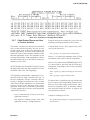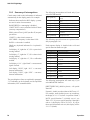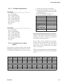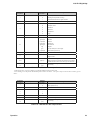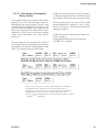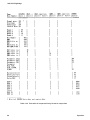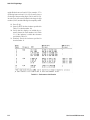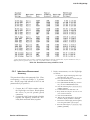
1
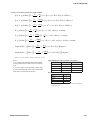
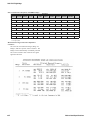
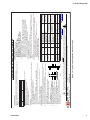
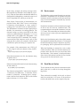
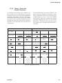
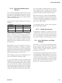
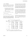
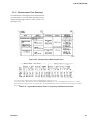
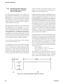
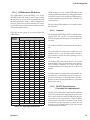
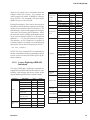
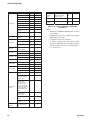
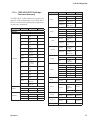
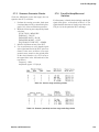
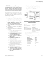
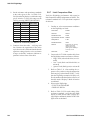
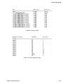
1693 RLC Digibridge
less than 1 kHz. The following tabulation indicates the
integration time for several combinations of I-T factor
and measurement rate, for test frequency of 1 kHz.
0.25
1
6
FAST
I-T Factor
1 ms
4 ms
24 ms
MEDIUM
4 ms
17 ms
100 ms
100 ms
100 ms
100 ms
SLOW
Not affected by
I-T factor
Table 3-9: Effects of Integration-Time factor on
Measure Rates
Programming the I-T factor is a special function,
which is under keyboard control only if you have
selected ENTER function. Then, for example, press
these keys:
[.][2][5][=][SHIFT][SPECIAL][5] (to make the IT factor
0.25)
NOTE: “Max” rate is defined as the combination of
FAST measure rate with I-T factor programmed to
be 0.25. (The quick- acquisition special function is
NOT used. See paragraph 3.10. With it, the measure
rate would be even higher.)
The accuracy of measurement is affected by the value
of I-T factor (in combination with measure rate and
other conditions). The tradeoff is illustrated as follows, for I-kHz test frequency, display = BIN NO.,
measurement mode = CONTINUOUS.
• I-T factor = any value, SLOW rate, 0.02% accuracy, 1 measurement per second;
• I-T factor = 1, MEDIUM rate, 0.05% accuracy,
4 measurements per second;
• I-T factor = 1, FAST rate, 0.12% accuracy, 8
measurements per second.
• I-T factor = 0.25, FAST rate (“Max”), 0.25%
accuracy, 23 measurements/second.
For details about accuracy, refer to the specifications,
where the effect of programming I-T factor to be 0.25
and selecting FAST rate is designated as “maximum
measurement rate” in the table of values for the term
“Ks.”
Operation
3.5.6 Ranges and Range Changing
Descriptions of ranges, range extensions, and decimal
point control are explained below.
Basic Ranges. The 4 basic ranges are numbered 1, 2,
3, 4, in order of decreasing impedance. Each basic
range is approximately a factor of 16 wide. Refer to
Table 3-7.
The word “upper” as used below refers to increasing
measured value (which is the direction of increasing range number only if the principal measured
parameter is capacitance) . Similarly, the word
“lower” as used below refers to decreasing measured
value (which is the direction of decreasing range
number only if the principal measured parameter is
capacitance).
Extensions. Each of the 4 ranges goes beyond its basic
range, with both upper and lower range extensions
(also called overrange and underrange). Most of these
extensions are seldom used because they overlap
basic portions of other ranges and the Digibridge
will automatically select the basic range unless you
have selected “hold range” (see RANGE HELD indicator). Measurement units and multipliers in any
range extension are the same as in the basic range.
The fact that range definition depends on frequency
causes a considerable variation in the width of range
extensions. The lower limit is generally .00001, with
all-zeros next; the upper limit is 99999, with all blanks
next. Blanks in the measurement display are discussed
below. In general, for any measurement within the
specifications of the Digibridge, if a measurement
can be displayed, it will be.
The only range extensions that are valid with autoranging are low underrange and high overrange,
explained below.
Low Underrange. The “low” extension of the low
range goes down to 1 count, with reduced accuracy.
The smallest “f-count” increment in the display is the
minimum measured value, given in the specifications
in the front of this manual. Any measurement smaller
than 1 count is displayed as all zeros.
47