1
I N S TA L L AT I O N
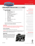
SKULL AIR CLEANER KIT FOR YAMAHA 9955
CUSTOMER SERVICE
877.370.3604 (toll free)
F I T S : ‘ 9 8 - ’ 0 5 V- S TAR 650
PART #
509944
909944
400545
609944
909422
609452
309955
INCLUDED
1
1
1
1
1
1
3
3
3
1
1
2
2
1
1
1
4
3
3
3
2
1
1
3
1
1
1
1
1
1
2
2
2
2
1
Skull Air Cleaner Assembly Including:
Skull Head Cover
Cage Assembly Black Powder Coated
Backing Plate
Dual Velocity Ring - Not Used
Mounting Hardware Kit Including:
1⁄4”-20 x 1” BSCS 18-8
1⁄4”-20 x 3⁄4” SHCS 18-8
1⁄4” Nylon Washer
K&N Air Filter
Plug & Elbow Kit Including:
1/8” NPT Hex Threaded Plug (1 used)
90 Degree Barbed Elbow (1 used)
Mounting Kit Including:
Rubber Manifold
Mounting Bracket
M6 Aluminum Spacer
1⁄4”-20 x 5/8” SHCS Alloy with Patch
1⁄4”-20 Nylock Nut
M6 Aluminum Tapered Bolt Cap
M6 x 1.0 mm x 30mm SHCS
M6 x 1.0mm x 16mm SHCS
6mm Serrated Flange Nut
M6 Flat Washer
18” 5/32” Vacuum Line (not used)
90 Degree Elbow
5” Hose 5/16” I.D.
Aluminum Pipe 3/8” x 1-1/4” Hose Splice
3 Way Barbed “T” Fitting (not used)
Jet Kit Including:
Pilot Jet
117.5 Main Jet
120.0 Main Jet
122.5 Main Jet
Installation Instructions
Not all parts will be used for this installation
THANK YOU FOR CHOOSING KURYAKYN!
DISCLAIMER – PLEASE READ BEFORE PROCEEDING:
Any modifications to a carbureted motorcycle’s exhaust or intake tract require carburetor rejetting to achieve maximum performance and maintain drivability. If you are uncomfortable
with the process of tuning your carburetor, we recommend that you bring your motorcycle to
a qualified motorcycle mechanic to have this kit installed.
-cont.9955-11MC-1005
INSTALLATION QUESTIONS
[email protected]
or call 715.247.2983
LIMITED WARRANTY
Küryakyn warrants that any Küryakyn products sold
hereunder, shall be free of defects in materials and
workmanship for a period of one (1) year from the
date of purchase by the consumer excepting the
following provisions:
• Küryakyn shall have no obligation in the event
the customer is unable to provide a receipt showing
the date the customer purchased the product(s).
• The product must be properly installed,
maintained and operated under normal conditions.
• Küryakyn makes no warranty, expressed or
implied, with respect to any gold plated products.
• Küryakyn shall not be liable for any consequential
and incidental damages, including labor and
paint, resulting from failure of a Küryakyn product,
failure to deliver, delay in delivery, delivery in nonconforming condition, or for any breech of contract or
duty between Küryakyn and a customer.
• Küryakyn products are often intended for use
in specific applications. Küryakyn makes no
warranty if a Küryakyn product is used in
applications other than intended.
• Küryakyn electrical products are warranted for one
(1) year from the date of purchase by the consumer.
Components of Küryakyn products containing L.E.D.s
will be warranted for defects in materials and
workmanship for 3 years from the date of purchase.
• Küryakyn makes no warranty of any kind in regard
to other manufacturer’s products distributed by
Küryakyn. Küryakyn will pass on all warranties made
by the manufacturer and where possible, will expedite the claim on behalf of the customer,
but ultimately, responsibility for disposition of the
warranty claim lies with the manufacturer.
ABOUT OUR CATALOG
You’ll find all our innovations for H-D, GL and
Metric Cruisers in our annual catalogs. Order online
today–select the ”CATALOGS” icon. Each Küryakyn™
product comes with a Proof-of-Purchase good for a
complimentary catalog. Details in packaging.
Be sure to ask your local dealer about other
Küryakyn products, the motorcycle parts and accessories designed for riders by riders.
©2005 Küryakyn USA™ All Rights reserved.
DISCLAIMER (CONT.)
The jets included in this kit were selected based on test results with various combinations of components
that we felt would represent the majority of the customers purchasing this kit. However, no two
motorcycles are exactly alike. Depending on the individual case, additional jets may need to be
purchased from an outside source. Kuryakyn warrants the parts included in this kit to be
PIC.1
free of defects in materials and workmanship, but makes no claim whatsoever in regard
to costs associated with installation or tuning.
NOTE
Please read each step of the instruction before proceeding with the
installation.
A
B
PROCEDURE
B
STEP 1 Remove the stock air cleaner and components to the point shown in PIC.1. The
stock plastic air box adapter “A” and stock mounting brackets “B” will remain in place.
B
STEP 2 Remove the carburetor according to the section in your factory service
manual that outlines procedures for carburetor removal, disassembly, reassembly and
installation.
Now is a good time to proceed with re-jetting the carburetor. Consult your factory service manual for
details of this procedure. We have supplied jets to cover many common configurations. Individual
bikes may need additional tuning to achieve maximum performance. If your exact combination is
not listed, choose the listing that most closely resembles the configuration of the motorcycle. These
recommendations are based on testing done at 700 feet above sea level.
COBRA/STOCK EXHAUST
Main Jet 120
Pilot Jet 35
PMS Screw 1-1/2 Turns Out From
Bottom
PIC.2
V&H STYLE OR OPEN PIPES
Main Jet 122.5
Pilot Jet 35
PMS Screw 1-1/2 Turns Out From
Bottom
NOTE
Your optimal performance and drivability may require some fine-tuning
from these specifications. For instance, the general rule of thumb is one jet size
smaller for every 3000-4000 feet of elevation.
A
D
D
Stock Intake Clamp
on adapter
B
C
STEP 3 Insert both flanges of the rubber adapter through the mounting bracket as
shown in PIC.2. The hardware components used for installation are placed near their
respective mounting points:
“A” Socket head cap screw — 30mm long, tapered bolt cap, and two spacers. The
spacers are placed between the chrome and the stock mounting brackets.
“B” Socket head cap screw — 15mm long, tapered bolt cap
“C” Socket head cap screw — 30mm long, tapered bolt cap, two spacers (place
between chrome and stock brackets), and flange nut.
“D” Mounting holes.
PIC.3
STEP 4 Install a Line Fitting Plug into the threaded hole in the back plate labeled as
“A” in PIC.3 and tighten snugly.
STEP 5 Install a 90 Degree Elbow into the threaded hole on the back plate labeled
as “B” in PIC.3. Tighten snugly.
-cont.-
B
A
PAGE
2
SKULL AIR CLEANER KIT
INSTALLATION
STEP 6 Insert the rubber intake duct through the back plate in the same fashion it was installed
in the main support bracket. See PIC.4. The back plate should be between the two rubber flanges
on the intake duct and the 90 Degree Elbow and Line Fitting Plug will be between the back plate
and the engine on the downward end of the plate. You may need to use a
PIC.4
screwdriver to help “poke” the flange of the Rubber Intake Boot into position
inside the back plate.
STEP 7 Line up the three holes in the back plate and the three holes in
the flange of the rubber intake duct with the three holes in the main support
bracket. Insert the three supplied 1/4”-20 X 5/8” socket head cap screws
through the back plate and secure on the back side of the main support
bracket with the 1/4”-20 thin Nylock nuts. You will need to pull back the inner
flange of the rubber intake duct to access the holes. Hold the Nylock nuts with
a 7/16” wrench as you tighten the socket head cap screws with a 3/16” hex
key. See PIC.4.
STEP 8 The opening in the adapter boot must be slipped over the flange
of the stock air box and secured with the stock clamp. Install the mounting
bracket as shown in PIC.5. Secure this assembly to the bike with the hardware
shown in PIC.2 and outlined in STEP 2. (The back plate was not installed for
PIC.5 to add clarity of assembly)
PIC.5
STEP 9 See PIC.6. Plug the extension into the float bowl vent hose and add
the 5”section of hose included. Connect this hose to the 90 degree fitting on
the backside of the back plate.
STEP 10 Set the air filter into position on the back plate. Place the cage over
the filter and secure with the 1⁄4”-20 x 1” BSCS fasteners provided.
STEP 11 Set the Skull cover in place, lining up the mounting holes with the
cage. Secure with the 1⁄4”-20 x 3⁄4” SHCS fasteners and clear nylon washers.
It would be a good idea to use blue lock tight (not supplied) on these fasteners.
Do not over tighten.
PIC.6
STEP 12 Check to make sure throttle is working free before starting engine.
-cont.FIG.1
Float bowl
vent hose
Hose
Extension
PAGE
3
H I - F I V E F O R V- S TA R
INSTALLATION
FIG.2
ADDENDUM I
The jets included in this kit were selected based on test results with various combinations of
components that we felt would represent the majority of the customers purchasing this kit.
However, no two motorcycles are exactly alike. Depending on the individual case, additional jets
may need to be purchased from an outside source. The following recommendations are intended as
a starting point and should work well in the majority of cases. Individual bikes may need additional
tuning to achieve maximum performance. If the exact combination is not listed, choose the listing
that most closely resembles the configuration of the motorcycle. These baselines were established at
700 feet above sea level.
PAGE
4
Ride On!
SKULL AIR CLEANER KIT
INSTALLATION