1
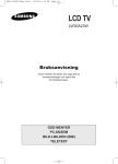
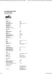
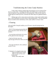
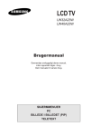
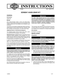
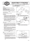
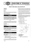
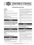
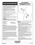
-J04664
REV. 2008-07-02
LUGGAGE RACK
GENERAL
is05565
Kit Number
9
1
8
10
52796-09
Models
For model fitment information, see the P&A Retail Catalog or
the Parts and Accessories section of www.harley-davidson.com
(English only).
5
Additional Parts Required
4
The rider's safety depends upon the correct installation
of this kit. Use the appropriate service manual procedures.
If the procedure is not within your capabilities or you do
not have the correct tools, have a Harley-Davidson dealer
perform the installation. Improper installation of this kit
could result in death or serious injury. (00333a)
7
6
1.
2.
3.
4.
5.
6.
7.
8.
9.
10.
NOTE
This instruction sheet references service manual information.
A service manual for your model motorcycle is required for this
installation and is available from a Harley-Davidson Dealer.
A 3 mil thick plastic sheet or bag approximately 18 in x 48 in
(46 cm x 123 cm) is required for this kit installation.
For Models with Denim Paint: 3M Adhesive Remover or
equivalent.
For All Other Paint: Harley Glaze Polish and Sealant (9970184).
Part Number
Not Sold Separately
Tape, double-sided foam (2)
53791-06
Dowel pin (4)
Not Sold Separately
Cover the belt guard and brake components with shop
rags. Follow the manufacturer's instructions for the
adhesive remover or Harley Glaze and remove all traces
of remaining adhesive. Do not allow adhesive remover to
drip onto the belt or brake components.
3.
Support the vehicle and raise the rear tire slightly off the
ground.
4.
See Figure 2. Remove the lower shock bolt (1) from each
shock.
5.
See Figure 1. Remove the turn signal bolt (7) and lower
the turn signal (4) and stalk (5) as an assembly. Repeat
for other side.
6.
Remove the mounting bolt (2).
REMOVAL
NOTE
For Non-FXDB Models: Remove the fender strut cover.
See service manual for specific information for these generalized steps.
1.
Repeat for other side.
Support the fender (9) and remove the mounting bracket
(3) from inside the fender. Gently lower the fender away
from the frame (10) being careful not to damage the paint.
Squeeze the fender slightly if necessary to lower the fender
between the arms of the frame.
1 of 2
Many Harley-Davidson® Parts & Accessories are made of plastics and metals which can be recycled.
Please dispose of materials responsibly.
See Figure 1. Remove the reflector (8) from the rear
fender. Use dental floss (or equivalent) and a sawing
motion if necessary to remove reflector. Repeat for the
other side.
-J04664
Spacer (2)
Mounting bolt (2)
Mounting bracket (2)
Turn signal (2)
Stalk (2)
Washer (2)
Turn signal bolt (2)
Reflector (2)
Fender
Frame (right side shown)
2.
Table 1. Kit Contents
Description (Qty)
3
Figure 1. Remove Fender Components
Kit Contents
Rack, solo rigid
2
7.
8.
9.
Fold the plastic sheet or bag (purchased separately) in
half and lay it over the fender to protect the paint. Make
sure the the plastic covers the six rack mounting holes in
the frame.
Remove the spacers (1) from the fender. If necessary,
use dental floss or equivalent to remove the spacers.
Be sure that all lights and switches operate properly before
operating motorcycle. Low visibility of rider can result in
death or serious injury. (00316a)
10. Test turn signals for proper operation.
NOTE
If desired, new reflectors can be purchased from a HarleyDavidson dealer.
is05564b
11. See Figure 4. Clean the back of the reflector, apply doublesided foam tape from the kit and install the reflector (1) on
the fender. Repeat for the other side.
1
Do not exceed luggage rack weight capacity. Too much
weight can cause loss of control, which could result in
death or serious injury. (00373a)
1. Lower shock bolt (2)
Figure 2. Remove Lower Shock Bolt (Right Side Shown)
INSTALLATION
1.
See Figure 3. Install the spacer (3) on the outside of the
front mounting hole of the rack (4). There should be
enough adhesive residue to allow the spacer to temporarily
adhere to the rack. Repeat for the other side.
2.
Gently position the rack inside the frame. Verify that the
spacers are still aligned with the mounting holes (4) and
the turn signal wires are routed through the slots of the
rack (2). Insert two dowel pins through the mounting holes
in the rack, through the spacer and frame to hold the rack
in place. Insert two dowel pins into the rear mounting holes
(1) and through the frame. Do not pinch the turn signal
wires with the dowel pins.
3.
4.
5.
Gently raise the fender into position, squeezing it slightly
if necessary. Use the dowel pins to hold it in place.
See Figure 1. Install the mounting bracket (3) from the
inside of the fender and align with the dowel pins. Push
the legs of the mounting bracket through the mounting
holes and plastic sheeting or bag, driving the dowel pins
out.
For Non-FXDB Models: Install fender strut cover and
mounting bolt (2). Tighten the mounting bolt finger-tight.
Repeat for other side.
NOTE
Maximum luggage rack weight capacity is 25 pounds (11.3
kg).
is05569
1.
2.
3.
4.
3
2
1
4
Rear mounting hole
Wire slot
Spacer
Front mounting hole
Figure 3. Rack Mounting
is05570
1
For FXDB Models: Install the mounting bolt and tighten
finger-tight. Repeat for other side.
6.
Install the turn signal bolt (7), washer (6) and turn signal
stalk (4) and assembly (5). Tighten bolt finger-tight.
7.
Remove plastic sheet.
8.
Tighten the turn signal bolts and mounting bolts to 12-16
ft-lbs (16-22 Nm). Repeat for the other side.
9.
Install the lower shock nut, bolt and washer. Tighten to
30-40 ft-lbs (41-54 Nm). Repeat for other side.
-J04664
1. Reflector (2)
Figure 4. Install Reflector
2 of 2